EP0342607B1 - Color image input unit having a rare gas cathode discharge tube - Google Patents
Color image input unit having a rare gas cathode discharge tube Download PDFInfo
- Publication number
- EP0342607B1 EP0342607B1 EP89108780A EP89108780A EP0342607B1 EP 0342607 B1 EP0342607 B1 EP 0342607B1 EP 89108780 A EP89108780 A EP 89108780A EP 89108780 A EP89108780 A EP 89108780A EP 0342607 B1 EP0342607 B1 EP 0342607B1
- Authority
- EP
- European Patent Office
- Prior art keywords
- discharge tube
- input unit
- light
- image input
- tube
- Prior art date
- Legal status (The legal status is an assumption and is not a legal conclusion. Google has not performed a legal analysis and makes no representation as to the accuracy of the status listed.)
- Expired - Lifetime
Links
- 239000000126 substance Substances 0.000 claims description 9
- 229910052724 xenon Inorganic materials 0.000 claims description 8
- FHNFHKCVQCLJFQ-UHFFFAOYSA-N xenon atom Chemical compound [Xe] FHNFHKCVQCLJFQ-UHFFFAOYSA-N 0.000 claims description 8
- 239000003086 colorant Substances 0.000 claims description 6
- 238000003860 storage Methods 0.000 claims description 5
- 229910052754 neon Inorganic materials 0.000 claims description 4
- GKAOGPIIYCISHV-UHFFFAOYSA-N neon atom Chemical compound [Ne] GKAOGPIIYCISHV-UHFFFAOYSA-N 0.000 claims description 4
- 230000001678 irradiating effect Effects 0.000 claims description 3
- 230000000638 stimulation Effects 0.000 claims 1
- 239000007789 gas Substances 0.000 description 40
- 238000003384 imaging method Methods 0.000 description 9
- QSHDDOUJBYECFT-UHFFFAOYSA-N mercury Chemical compound [Hg] QSHDDOUJBYECFT-UHFFFAOYSA-N 0.000 description 7
- 229910052753 mercury Inorganic materials 0.000 description 7
- 229910052751 metal Inorganic materials 0.000 description 6
- 239000002184 metal Substances 0.000 description 6
- 238000000034 method Methods 0.000 description 6
- 239000000853 adhesive Substances 0.000 description 5
- 230000001070 adhesive effect Effects 0.000 description 5
- 230000003287 optical effect Effects 0.000 description 5
- 238000000926 separation method Methods 0.000 description 5
- 239000003990 capacitor Substances 0.000 description 4
- 238000004519 manufacturing process Methods 0.000 description 4
- 238000010276 construction Methods 0.000 description 3
- 230000005284 excitation Effects 0.000 description 3
- XKRFYHLGVUSROY-UHFFFAOYSA-N Argon Chemical compound [Ar] XKRFYHLGVUSROY-UHFFFAOYSA-N 0.000 description 2
- OKTJSMMVPCPJKN-UHFFFAOYSA-N Carbon Chemical compound [C] OKTJSMMVPCPJKN-UHFFFAOYSA-N 0.000 description 2
- OAICVXFJPJFONN-UHFFFAOYSA-N Phosphorus Chemical compound [P] OAICVXFJPJFONN-UHFFFAOYSA-N 0.000 description 2
- 229910052799 carbon Inorganic materials 0.000 description 2
- 238000006243 chemical reaction Methods 0.000 description 2
- 238000010586 diagram Methods 0.000 description 2
- 238000009826 distribution Methods 0.000 description 2
- 238000010894 electron beam technology Methods 0.000 description 2
- 230000007613 environmental effect Effects 0.000 description 2
- 239000011521 glass Substances 0.000 description 2
- 238000010438 heat treatment Methods 0.000 description 2
- 238000004020 luminiscence type Methods 0.000 description 2
- 239000000463 material Substances 0.000 description 2
- 239000000843 powder Substances 0.000 description 2
- 229920006395 saturated elastomer Polymers 0.000 description 2
- 230000003595 spectral effect Effects 0.000 description 2
- 229910000906 Bronze Inorganic materials 0.000 description 1
- RYGMFSIKBFXOCR-UHFFFAOYSA-N Copper Chemical compound [Cu] RYGMFSIKBFXOCR-UHFFFAOYSA-N 0.000 description 1
- 206010017577 Gait disturbance Diseases 0.000 description 1
- GWEVSGVZZGPLCZ-UHFFFAOYSA-N Titan oxide Chemical compound O=[Ti]=O GWEVSGVZZGPLCZ-UHFFFAOYSA-N 0.000 description 1
- 229910021417 amorphous silicon Inorganic materials 0.000 description 1
- 229910052786 argon Inorganic materials 0.000 description 1
- 230000015572 biosynthetic process Effects 0.000 description 1
- 239000010974 bronze Substances 0.000 description 1
- 229910052802 copper Inorganic materials 0.000 description 1
- 239000010949 copper Substances 0.000 description 1
- KUNSUQLRTQLHQQ-UHFFFAOYSA-N copper tin Chemical compound [Cu].[Sn] KUNSUQLRTQLHQQ-UHFFFAOYSA-N 0.000 description 1
- 230000007423 decrease Effects 0.000 description 1
- 230000002950 deficient Effects 0.000 description 1
- 238000007598 dipping method Methods 0.000 description 1
- 239000006185 dispersion Substances 0.000 description 1
- RUZYUOTYCVRMRZ-UHFFFAOYSA-N doxazosin Chemical compound C1OC2=CC=CC=C2OC1C(=O)N(CC1)CCN1C1=NC(N)=C(C=C(C(OC)=C2)OC)C2=N1 RUZYUOTYCVRMRZ-UHFFFAOYSA-N 0.000 description 1
- 230000000694 effects Effects 0.000 description 1
- 229910052736 halogen Inorganic materials 0.000 description 1
- 150000002367 halogens Chemical class 0.000 description 1
- 229910052734 helium Inorganic materials 0.000 description 1
- 239000001307 helium Substances 0.000 description 1
- SWQJXJOGLNCZEY-UHFFFAOYSA-N helium atom Chemical compound [He] SWQJXJOGLNCZEY-UHFFFAOYSA-N 0.000 description 1
- 238000009413 insulation Methods 0.000 description 1
- 229910052743 krypton Inorganic materials 0.000 description 1
- DNNSSWSSYDEUBZ-UHFFFAOYSA-N krypton atom Chemical compound [Kr] DNNSSWSSYDEUBZ-UHFFFAOYSA-N 0.000 description 1
- WABPQHHGFIMREM-UHFFFAOYSA-N lead(0) Chemical compound [Pb] WABPQHHGFIMREM-UHFFFAOYSA-N 0.000 description 1
- 239000007788 liquid Substances 0.000 description 1
- 239000000203 mixture Substances 0.000 description 1
- 230000000704 physical effect Effects 0.000 description 1
- 229920000515 polycarbonate Polymers 0.000 description 1
- 239000004417 polycarbonate Substances 0.000 description 1
- 238000007639 printing Methods 0.000 description 1
- 229910052704 radon Inorganic materials 0.000 description 1
- SYUHGPGVQRZVTB-UHFFFAOYSA-N radon atom Chemical compound [Rn] SYUHGPGVQRZVTB-UHFFFAOYSA-N 0.000 description 1
- 239000011347 resin Substances 0.000 description 1
- 229920005989 resin Polymers 0.000 description 1
- 239000004065 semiconductor Substances 0.000 description 1
- 230000035945 sensitivity Effects 0.000 description 1
- 230000001360 synchronised effect Effects 0.000 description 1
- XOLBLPGZBRYERU-UHFFFAOYSA-N tin dioxide Chemical compound O=[Sn]=O XOLBLPGZBRYERU-UHFFFAOYSA-N 0.000 description 1
- 229910001887 tin oxide Inorganic materials 0.000 description 1
- OGIDPMRJRNCKJF-UHFFFAOYSA-N titanium oxide Inorganic materials [Ti]=O OGIDPMRJRNCKJF-UHFFFAOYSA-N 0.000 description 1
- 239000012780 transparent material Substances 0.000 description 1
- 238000004804 winding Methods 0.000 description 1
Images


Classifications
-
- H—ELECTRICITY
- H01—ELECTRIC ELEMENTS
- H01J—ELECTRIC DISCHARGE TUBES OR DISCHARGE LAMPS
- H01J61/00—Gas-discharge or vapour-discharge lamps
- H01J61/02—Details
- H01J61/54—Igniting arrangements, e.g. promoting ionisation for starting
- H01J61/541—Igniting arrangements, e.g. promoting ionisation for starting using a bimetal switch
- H01J61/544—Igniting arrangements, e.g. promoting ionisation for starting using a bimetal switch and an auxiliary electrode outside the vessel
-
- H—ELECTRICITY
- H01—ELECTRIC ELEMENTS
- H01J—ELECTRIC DISCHARGE TUBES OR DISCHARGE LAMPS
- H01J61/00—Gas-discharge or vapour-discharge lamps
- H01J61/02—Details
- H01J61/56—One or more circuit elements structurally associated with the lamp
Definitions
- the present invention relates to a color image input unit having a rare gas cold cathode discharge tube.
- Image input units are used for reading images such as photographs and the like and generating corresponding data which can be input into a computer.
- Known image input units may be classified into mainly three types depending on their reading system.
- the first type is a camera type image input unit using a two-dimensional array of photoelectric transducer elements onto which the image to be read is projected. An image is read during 20 ms or less.
- This camera type image input unit is mainly used for reading images changing with time. Since an optical path length for imaging must be secured in construction, a large space will be required for the unit. Furthermore, since all of a picture image to be read must be irradiated at once and since it is difficult to irradiate a greater area by a uniform brightness, a high accuracy in reading the density values of the picture is hardly achieved. Still further, since the photoelectric transducer elements are arrayed two-dimensionally, a high precision technique is required for manufacturing, leading to high manufacturing costs.
- the second type of image input unit is a drum scanner using an imaging system and a photoelectric transducer element for reading an image point by point. While a picture image is rotating on a drum, the photoelectric transducer element is shifted into the axial direction of the drum.
- the reading resolution may be readily selected, and a relatively high resolution may be obtained.
- the resolution depends on the mechanical precision of the component parts, high cost may result and a large-sized construction will be quite unavoidable with this type of image input unit.
- the third type of image input unit uses a one-dimensional array of photoelectric transducer elements consisting of CCD (charge coupled devices) or the like. Synchronized with data reading, the photoelectric transducer elements are shifted relative to a picture image in a direction perpendicular to the extension of the array, thereby scanning the image line by line.
- This third type of image input unit may be regarded as a system intermediate of the aforementioned two types and enjoying the advantages of those two other types.
- the reading rate of this third type of image input unit is higher than that of the drum scanner and the space required for the unit is the minimum among the three types.
- the image scanner type image input unit using a one-dimensional array of photoelectric transducer elements is optimum as it is cheap, small-sized and allows a high resolution.
- a lighting apparatus used in such an image scanner has to irradiate a picture image in the direction where the photoelectric transducer elements are arrayed.
- An LED array, a fluorescent lamp, a linear halogen lamp and the like are employed for this purpose.
- a sufficient tone representation capacity is required for the image input unit, and unless the density values of the picture image are quantized into for example 8 to 256 gradations, a picture image such as a photograph or the like with a fine change in intermediate density cannot be loaded accurately into a computer. It is necessary therefore that the picture image be irradiated uniformly by a constant brightness, and hence a lighting apparatus emitting a stabilized quantity of light is necessary.
- a rare gas cold cathode discharge tube filled with xenon or neon gas With a rare gas cold cathode discharge tube filled with xenon or neon gas, the quantity of light is almost constant regardless of the working environmental temperature as compared to a general mercury discharge lamp, as to be taken from Fig. 16. Accordingly, when a conventional mercury discharge lamp is used, it must be warmed up by a heating apparatus like an electric heater. This requires a time of 1 to 2 minutes before such a lamp can actually be used. Instead, the rare gas cold cathode discharge tube is ready for use as soon as the power is switched on. Since a heating for the electrodes is not necessary, a rare gas cold cathode discharge tube can be made small in shape and miniaturized in overall size to, for example, a diameter of 1 to 6 mm.
- the power consumption is low, for example 4 to 10 watts.
- the luminous color can be arbitrarily selected depending on a fluorescent material applied to the inside of the tube wall. Therefore, a rare gas cold cathode discharge tube is appropriate not only for facsimile machines but also as a light source of an image scanner for reading color picture images.
- the color correction can be carried out in real time in keeping pace with reading, and data after the color correction may be sent to a host computer.
- RAM semiconductor memory
- a color image input unit operating according to the above explained line sequential reading system and employing mercury discharge lamps, namely one for generating a green light with an afterglow characteristics, one for generating a red light with no afterglow characteristics and a further one for generating a blue light with no afterglow characteristics is disclosed in the document EP-A-0 165 550.
- the rare gas cold cathode discharge tube is advantageous with respect to the stability of the quantity of light against environmental temperature change, space occupation and so on as compared with a general mercury discharge lamp. It is defective, however, insofar as a light source for reading picture images is concerned. That is, the quantity of light in intermittent lighting which is necessary for a line sequential reading is not stabilized.
- the rare gas cold cathode discharge tube has been used so far under the condition that it was kept lighting continuously for several seconds or longer each time it was energized. In the case of a rare gas cold cathode discharge tube, the gas pressure is 7 to 27 kPa (50 to 200 mmHg) high, while it is a few kPa (10 mmHg) with general mercury discharge lamps.
- an auxiliary electrode is provided along the wall of the tube (DE-A-37 18 216).
- the positive column when repeating the intermittent lighting at a period of several millise conds or so, the positive column is not stably drawn toward the auxiliary electrode. Therefore, the quantity of light of the rare gas cold cathode discharge tube is not fixed and the brightness of the read image changes. Specifically, while the positive column exists at all times, the light emitting position fluctuates within the discharge tube to come near or to go away from the picture image, and thus the quantity of light irradiating the picture image fluctuates by 1 to 10 percent.
- the present invention is intended to remedy the above mentioned problems of the prior art and to provide an image input unit having a rare gas cold cathode discharge tube emitting a stabilized quantity of light even if it is intermittently lit at a period of several milliseconds or so, and which is moderate in cost and high in performance.
- FIG. 3 is a perspective view of an image input unit according to a first embodiment of the invention.
- an image reading unit 10 is shifted successively in the direction indicated by an arrow, by a driving device such as a stepping motor or the like through a timing belt, a wire or the like which is not shown.
- Fig. 4 is a sectional view taken on line A-A′ in Fig. 3 of the image reading unit 10.
- Fig. 4 three cold cathode discharge tubes 1-R, 1-B, 1-G filled with rare gas, which constitute a lighting apparatus, are used for reading the picture image 7 placed on a glass bed 6 and emit red, blue and green light, respectively.
- the red tube 1-R is filled with a neon gas under a pressure of 1,3 to 6,7 kPa (10 to 50 Torr), preferably 2,7 kPa (20 Torr).
- a red color is obtained by the luminescence of the gas itself.
- an aperture formed inside or outside of the tube wall by a white film of titanium oxide powder or the like will be effective in directing the light efficiently for irradiation.
- the blue and green discharge tubes 1-B and 1-G are filled with xenon gas under a pressure of 8 to 20 kPa (60 to 150 Torr), preferably 10,7 kPa (80 Torr).
- the tube voltage to be impressed on the discharge tube rises proportionally to the pressure. Since a high voltage requires an expensive driver circuit, the pressure values specified above will be appropriate.
- FIG. 4 A color picture reading method will be described next with reference to Fig. 4 and the timing chart of Fig. 14.
- the image reading unit 10 shown in Fig. 4 is first shifted to an image reading start position by a driving signal shown under (f) in Fig. 14. Then, light of the three primary colors is successively irradiated onto the picture image 7 under the control of lighting signals shown as (a), (c) and (d), respectively, in Fig. 14.
- the reflected light is respectively imaged on a photoelectric transducer 3 by an imaging system 2.
- the photoelectric transducer 3 is properly amplified, processed and sent to a host computer (not shown) as a one-dimensional image information of red, blue and green of the picture image.
- the above operation is repeated to store on the host computer side one-dimensional color image data shifted little by little in the direction perpendicular to the array of photoelectric transducer elements in the photoelectric transducer 3, thus reading a two-dimensional color image by means of the one-dimensional photoelectric transducer.
- the rare gas cold cathode discharge tubes are lighted for 5 ms each, and the photoelectric transducer operates for 5 ms for reading, thus finishing the basic reading operation in about 30 ms.
- the lighting time and period are representative in value, and a signal precision and a read rate can be further enhanced by properly selecting the disposition of the rare gas cold cathode discharge tubes and the sensitivity of the photoelectric transducer elements.
- Trm an afterglow removing time Trm, shown in Fig. 14, must be set. Unless it is set, the irradiation of red light following that of green light will be mixed with the green light due to the afterglow and, thus, the reproducibility of the red picture image is deteriorated. Trm should be as short as possible since it directly influences the read rate. Depending on the capacity of the used phosphor, a value of 1 to 20 ms, preferably 5 ms, is appropriate.
- a preliminary lighting (intermittent or normally light-on) will be effected for 10 to 100 ms before the start of reading, and the light is switched off when the image reading unit 10 is reset to a reference position after the reading has been completed.
- a white reference picture image uniform in reflection factor is read to obtain reference data.
- Data read from a real picture image are then corrected by means of the reference data, thereby obtaining data correctly representing the density distribution of the read image.
- xenon is the proper rare gas to be charged into the cold cathode discharge tube.
- rare gas other than xenon may be used if a fluorescent substance is developed having its excitation wave length adjusted to the wave length of the light emitted by said other rare gas.
- a fluorescent substance having an excitation wave length of 389 nm is used, helium will be appropriate as the rare gas.
- Rare gases such as argon, krypton, radon and the like are usable likewise.
- the image reading unit 10 can be constructed compactly by using a platelike or rodlike glass of a proper refractive index distribution as the imaging system 2.
- the light emitted by the discharge tubes 1-B, 1-G, 1-R and reflected by the picture image 7 is condensed by the imaging system 2 and irradiated on the photoelectric transducer 3.
- a reflector 4 consists of a white resin such as polycarbonate or the like and functions to condense and reflect the light from the lighting apparatus in the direction of the picture image 7.
- Discharge tube 1 is controlled for lighting and fed with electric power by a driver circuit 12 to which two main electrodes 13-a and 13-b and an auxiliary electrode 14 of the discharge tube are electrically connected.
- Fig. 15 is a circuit diagram representing one example of the driver circuit 12.
- a battery E is shown as a power source providing 12V or 24V DC power.
- a transistor TR3 is switched on, energizing an inverter circuit including transistors TR1 and TR2 and a boosting transformer T.
- a high-voltage, high-frequency alternating current 500 to 2000V and 10 to 50 kHz is induced in the secondary winding of the boosting transformer T and applied to the discharge tube 1. Thereby, discharge tube 1 is controlled for lighting.
- Capacitors C1, C2 and C3 function to limit the current flowing through the discharge tube and their capacitance is 50 to 200 pF, preferably 120 pF.
- Capacitors C4 and C5 function to stabilize the positive column or bright line formed by the current flowing through the discharge tube. Their capacitance is 5 to 30 pF or so.
- the potential of the main electrodes 13-a, 13-b is stabilized by providing the capacitors, and a stable discharge state can be maintained even at the time of intermittent lighting in which the discharge tube is switched on and off repeatedly at milliseconds. It is preferable that one of the terminals of the capacitors C4 and C5 be grounded.
- the auxiliary electrode 14 may be a strip of a hardened, conductive adhesive containing carbon for example, the width of the strip being 0,1 to 2 mm, preferably 0,8 mm and its resistance value 1 to 20 k ⁇ , preferably 3 to 6 k ⁇ per centimeter length.
- Fig. 2 is a perspective enlarged partial view of the discharge tube of Fig. 1, for illustrating the discharge process at the main electrode 13-a and its neighborhood.
- a ring-shaped conductive member 15 of a conductive adhesive containing a powder such as for example copper, carbon or the like is formed on the discharge tube wall around the inner end of the main electrode 13-a (actually, the conductive member 15 is displaced with respect to the inner axial end of the main electrode 13-a in the axial direction for reasons stated later).
- the electrode 13-a has the same electrical potential as that of the auxiliary electrode 14, whereas the electrode 13-b has the reverse electrical potential of that of the auxiliary electrode 14.
- the conductive member 15 is electrically connected with the auxiliary electrode 14.
- the driver circuit 12 When the high-voltage, high-frequency AC voltage is applied to the main electrodes 13-a, 13-b by the driver circuit 12, an electron beam is generated between the main electrodes 13-a and 13-b through the rare gas, for example xenon gas.
- the electron beam brings the rare gas into a plasma state, and excites it to emit ultraviolet rays, visible light and infrared rays, as is characteristic for the gas. This develops to a bright line which is observed as a positive column 17.
- the ultraviolet rays excite the fluorescent substance applied to the inner wall of the discharge tube. A luminescence of arbitrary visible light as blue, green, red, white and so on may be obtained by selecting the kind of fluorescent substance.
- a voltage is impressed on the auxiliary electrode 14 by the driver circuit 12 in order to establish a potential difference between the main electrode 13-b and the auxiliary electrode 14. Due to this potential difference, the positive column 17 generated between the main electrodes is drawn to the discharge tube inner wall along the auxiliary electrode 14 and stabilized firmly.
- the positive column generated from the main electrode 13-a at the time of lighting start is drawn to the side of the piece of metal (indicated as 17-a in Fig. 2) and its path will not be stabilized along the auxiliary electrode 14 (the same effect will occur with any material other than a piece of metal, provided that it establishes a capacitance to the positive column of discharge and exerts an influence on the formation of the positive column.
- the conductive member 15 functions to supress a deflection of the positive column
- the above mentioned problems occur when the piece of metal 16 is disposed in a region surrounding the nose or inner end of the main electrode 13-a.
- the positive column is drawn thereto, since the conductive member 15 and the auxiliary electrode 14 are of the same potential, the positive column is caught on the conductive member 15 and a path 17-b is formed immediately along the auxiliary electrode 14. Once the positive column is caught on the auxiliary electrode 14, the position of the positive column is stabilized since it never comes outside of the position of the auxiliary electrode 14, even if a piece of metal 16 or any equivalent member is disposed nearby.
- the conductive member 15 will preferably be positioned ahead (towards the opposite main electrode) of a discharge position of the main electrode. Concretely, it may preferably by displaced by 1 to 5 mm or so from the axial inner end of the main electrode.
- Fig. 17 is a diagrammatic view showing the positional relation between the discharge tube 1 and the picture image 7.
- the total length of the discharge tube must be long enough such that the length of a portion of the discharge tube emitting a substantially uniform quantity of light covers the width of the picture image 7 to be read.
- the conductive member 15 is made of a transparent material like tin oxide, it is required to be positioned 3 to 10 mm outside of the adjacent edge of the picture image in order to ensure a uniform quantity of light over the whole width of the picture image.
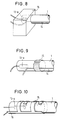
- Figs. 5 to 10 are diagrammatic partial views of alternative embodiments of the rare gas cold cathode discharge tube according to the invention.
- the conductive member 15 consists of a spring piano wire which is fixed on the discharge tube wall by the spring force and which is electrically connected to the auxiliary electrode 14 formed of a conductive adhesive.
- this embodiment is simplified not needing the application of the conductive adhesive for forming the conductive member 15, and thus is moderate in cost.
- a lead wire for connecting the auxiliary electrode 14 to the driver circuit 12 (Fig. 1) is wound on the discharge tube wall, thus forming a conductive member 15 at the same time.
- the conductive member 15 is formed by dipping the end of the discharge tube into a liquid conductive adhesive which is then hardened. In this case, care must be taken to ensure the necessary insulation between the conductive member 15 and the main electrode.
- the conductive member 15 consists of a metallic box-like member or the like, serving as fixing means for the discharge tube at the same time and, hence simplifying the construction.
- the conductive member 15 does not necessarily need to form a closed ring around the discharge tube wall and still may be effective enough to stabilize the positive column.
- a sheet metal of phosphor bronze having spring characteristics and a thickness of about 0.2 mm is curved cylindrically and fixed on the discharge tube wall.
- this conductive member 15 is capable of functioning as a positioning member in the circumferential direction when the discharge tube is fixed.
- a tricolor light source 1-G, 1-B, 1-R Shown diagrammatically in Fig. 11 is an alternative embodiment of the image reading unit wherein the color separation is realized by a filter.
- a white rare gas cold cathode discharge tube 1 is used for irradiating the picture image 7.
- the white discharge tube called a three-wavelength type discharge tube, is obtainable by using as a fluorescent substance a mixture of green, red and blue emitting substances.
- the image is formed on a CCD photoelectric transducer 3 via a mirror 20 and an imaging system 2. More than one mirror may be used in order to minimize the general volume of the unit.
- a tricolor filter 21 including green, red and blue filter portions is disposed in the imaging optical path.
- a driving device 22 is used to shift the green, red and blue filter portions successively into the imaging optical path. Since the filter portions of the filter 21 must be changed within a short time of several milliseconds, the filter 21 advantageously is formed as a circular plate segmented into three 120° portions corresponding to the green, red and blue filter portions. In this case, driving device 22 could be a motor switching from one filter portion to another by a rotation of 120° of the filter plate.
- the three-wavelength type white cold cathode discharge tube 1 is intermittently driven chiefly for adjusting the quantity of light inputted to the photoelectric transducer (MOS type transducer, CCD transducer or the like). The reason for that will be described below.
- Fig. 18 represents a conversion characteristic of a MOS type photoelectric transducer element consisting of amorphous silicon (the situation with a CCD transducer element is similar).
- the photoelectric transducer element generally called a storage type transducer
- an output is obtainable in proportion to the integrated quantity of light irradiated within the reading period (domain B in Fig. 18).
- a background output called noise (domain C in the drawing). This is called a dark output.
- the S/N ratio indicating the precision of the read signals is expressed as the ratio of a signal output to the dark output. Of course, the larger the S/N ratio, the better it is.
- the integrated quantity of light to the photoelectric transducer element has a saturation threshold (domain A in the drawing), i.e. the output voltage of the transducer element becomes constant even if further light is applied. If saturation is reached, a density change in the picture image can no longer be read correctly. Accordingly, for better precision of an outgoing signal to be extracted, an irradiation lot of the light to use will come in the domain B in Fig. 18. For best results, the amount of light will be just below the saturation point.
- the lighting time of the rare gas cold cathode discharge tube should be set to an optimum value.
- the quantity of light emitted by the discharge tube varies from tube to tube in a mass production according to a statistical dispersion. If the output signal is saturated (domain A in Fig. 18), then the output becomes constant, not reflecting the image density. Therefore, the lighting time at the time of shipment is set somewhat short as compared with the time at which the output is saturated. Further, the quantity of light decreases gradually from a continuous service and thus the S/N ratio drops. Therefore, the capacity inherent in the photoelectric transducer element cannot be made full use of.
- the lighting time of the light source is adjusted to set an optimum quantity of light for the photoelectric transducer elements whenever the image input unit is used.
- an intermittent lighting is carried out as mentioned before.
- the quantity of light may be stabilized by using the conductive member 15 on the tube wall due to the reasons mentioned above.
- Fig. 12 diagrammatically shows a further embodiment of the image reading unit according to the invention.
- separate color signals are obtained at a time by providing the transducer elements themselves with a filter at the state of manufacturing. Since mechanically operating parts are not required for color separation, problems like a vibration generated from such operating parts or the like will not occur.
- the three-wavelength type white cold cathode discharge tube 1 is intermittently lighted in this embodiment, too.
- the conductive member 15 is preferably used with the discharge tube 1 in this embodiment.
- Fig. 13 is a diagrammatic view of still another embodiment of the image reading unit according to the invention. While the embodiment of Fig. 4 uses a magnifying imaging optical system, the optical system 2 of the embodiment shown in Fig. 13 is of the reducing type, reducing to one-fifth to one-tenth or so. Like the embodiment shown in Fig. 4, the color separation is achieved by using three discharge tubes 1-R, 1-B and 1-G.
- the intermittent lighting is a discharge tube lighting method required particularly for light adjustment and line sequential reading for color correction. Further, a noise of a high frequency of 20 to 30 kHz produced at the time of discharge tube lighting during the normal reading is capable of affecting the output of the photoelectric transducer. It is therefore effective to carry out an intermittent lighting of the discharge tube including the three-wavelength type tube and also to generate an output of the photoelectric transducer when putting out the light.
- a rare gas cold cathode discharge tube is provided, allowing to stabilize the quantity of emitted light even when an intermittent lighting with a period of several milliseconds is carried out.
- the use of such rare gas cold cathode discharge tube as lighting apparatus allows an image input unit to be realized which is moderate in cost and less space-consuming, still ensuring a color correction function to enhance the color reproducibility of a printing output of the read image and a light adjusting function of the lighting apparatus to enhance the S/N ratio of the read image.
Landscapes
- Facsimile Scanning Arrangements (AREA)
Description
- The present invention relates to a color image input unit having a rare gas cold cathode discharge tube.
- Image input units are used for reading images such as photographs and the like and generating corresponding data which can be input into a computer. Known image input units may be classified into mainly three types depending on their reading system.
- The first type is a camera type image input unit using a two-dimensional array of photoelectric transducer elements onto which the image to be read is projected. An image is read during 20 ms or less. This camera type image input unit is mainly used for reading images changing with time. Since an optical path length for imaging must be secured in construction, a large space will be required for the unit. Furthermore, since all of a picture image to be read must be irradiated at once and since it is difficult to irradiate a greater area by a uniform brightness, a high accuracy in reading the density values of the picture is hardly achieved. Still further, since the photoelectric transducer elements are arrayed two-dimensionally, a high precision technique is required for manufacturing, leading to high manufacturing costs.
- The second type of image input unit is a drum scanner using an imaging system and a photoelectric transducer element for reading an image point by point. While a picture image is rotating on a drum, the photoelectric transducer element is shifted into the axial direction of the drum. By controlling the rotational speed of the drum and the moving rate of the photoelectric transducer, the reading resolution may be readily selected, and a relatively high resolution may be obtained. However, since the resolution depends on the mechanical precision of the component parts, high cost may result and a large-sized construction will be quite unavoidable with this type of image input unit.
- The third type of image input unit uses a one-dimensional array of photoelectric transducer elements consisting of CCD (charge coupled devices) or the like. Synchronized with data reading, the photoelectric transducer elements are shifted relative to a picture image in a direction perpendicular to the extension of the array, thereby scanning the image line by line. This third type of image input unit may be regarded as a system intermediate of the aforementioned two types and enjoying the advantages of those two other types. The reading rate of this third type of image input unit is higher than that of the drum scanner and the space required for the unit is the minimum among the three types.
- As described above, it can be said that the image scanner type image input unit using a one-dimensional array of photoelectric transducer elements is optimum as it is cheap, small-sized and allows a high resolution.
- A lighting apparatus used in such an image scanner has to irradiate a picture image in the direction where the photoelectric transducer elements are arrayed. An LED array, a fluorescent lamp, a linear halogen lamp and the like are employed for this purpose. A sufficient tone representation capacity is required for the image input unit, and unless the density values of the picture image are quantized into for example 8 to 256 gradations, a picture image such as a photograph or the like with a fine change in intermediate density cannot be loaded accurately into a computer. It is necessary therefore that the picture image be irradiated uniformly by a constant brightness, and hence a lighting apparatus emitting a stabilized quantity of light is necessary.
- With a rare gas cold cathode discharge tube filled with xenon or neon gas, the quantity of light is almost constant regardless of the working environmental temperature as compared to a general mercury discharge lamp, as to be taken from Fig. 16. Accordingly, when a conventional mercury discharge lamp is used, it must be warmed up by a heating apparatus like an electric heater. This requires a time of 1 to 2 minutes before such a lamp can actually be used. Instead, the rare gas cold cathode discharge tube is ready for use as soon as the power is switched on. Since a heating for the electrodes is not necessary, a rare gas cold cathode discharge tube can be made small in shape and miniaturized in overall size to, for example, a diameter of 1 to 6 mm. The power consumption is low, for example 4 to 10 watts. The luminous color can be arbitrarily selected depending on a fluorescent material applied to the inside of the tube wall. Therefore, a rare gas cold cathode discharge tube is appropriate not only for facsimile machines but also as a light source of an image scanner for reading color picture images.
- However, if a picture image read by the color image scanner is printed straightly by a color printer, the printed picture image will be dark, different in hue and inferior in saturation with respect to the original picture image. The reason is that the reflective spectral characteristic of the existing color ink is not ideal. Therefore, a color data translation work will be necessary in order to correct an unbalanced color due to the spectral characteristic of the ink used in a printer. This is called color correction and is a usual practice for obtaining a printed matter having colors actually corresponding to those of the original picture image.
- For the color correction, density values of the three primary colors such as green, red and blue will be necessary per picture element, the number of picture elements depending on the reading resolution. The volume of data of the three primary colors to be loaded by means of the color image scanner becomes extraordinarily high, an apparatus for realizing the color correction becomes expensive and the calculating time necessary for the color correction becomes long. This is one of the stumbling blocks not allowing a printed matter bright in color to be realized on general computers.
- Now, therefore, what is contrived as available for attaining correction swiftly and cheaply is a reading system in line sequence. In the conventional system which is called a page sequential system, the whole color picture is separately read for each primary color by reciprocating three times in the order of green, red and blue. Instead, in the line sequential system, data of the three primary colors green, red and blue are loaded at every scanning line, finishing the reading of the full picture image by scanning it only one time. In the line sequential reading system, a data volume necessary for the color correction may be minimized to one per several thousands (in the case of A4 size), which is advantageous as compared with the page sequential system. Using a semiconductor memory (RAM) capable of writing and reading as a storage device for color correction and providing an integrated circuit for exclusive use on color correction in the image scanner, the color correction can be carried out in real time in keeping pace with reading, and data after the color correction may be sent to a host computer.
- A color image input unit operating according to the above explained line sequential reading system and employing mercury discharge lamps, namely one for generating a green light with an afterglow characteristics, one for generating a red light with no afterglow characteristics and a further one for generating a blue light with no afterglow characteristics is disclosed in the document EP-A-0 165 550.
- As described above, the rare gas cold cathode discharge tube is advantageous with respect to the stability of the quantity of light against environmental temperature change, space occupation and so on as compared with a general mercury discharge lamp. It is defective, however, insofar as a light source for reading picture images is concerned. That is, the quantity of light in intermittent lighting which is necessary for a line sequential reading is not stabilized. The rare gas cold cathode discharge tube has been used so far under the condition that it was kept lighting continuously for several seconds or longer each time it was energized. In the case of a rare gas cold cathode discharge tube, the gas pressure is 7 to 27 kPa (50 to 200 mmHg) high, while it is a few kPa (10 mmHg) with general mercury discharge lamps. Therefore, a straight bright line called positive column is observed along the discharge tube at the time of lighting. For locating the positive column stably at a specified portion in the circumferential direction of the rare gas cold cathode discharge tube, an auxiliary electrode is provided along the wall of the tube (DE-A-37 18 216).
- However, in the aforementioned prior art, when repeating the intermittent lighting at a period of several millise conds or so, the positive column is not stably drawn toward the auxiliary electrode. Therefore, the quantity of light of the rare gas cold cathode discharge tube is not fixed and the brightness of the read image changes. Specifically, while the positive column exists at all times, the light emitting position fluctuates within the discharge tube to come near or to go away from the picture image, and thus the quantity of light irradiating the picture image fluctuates by 1 to 10 percent. In a high performance image scanner for reading a picture image of fine density values at gradations of 32 to 256, even such several percent fluctuation of the quantity of light may exert an influence on the reproduced picture, and a stripe is produced even if a uniform density picture is read.
- The present invention is intended to remedy the above mentioned problems of the prior art and to provide an image input unit having a rare gas cold cathode discharge tube emitting a stabilized quantity of light even if it is intermittently lit at a period of several milliseconds or so, and which is moderate in cost and high in performance.
- This object is achieved with a color image input unit as claimed.
- Specific embodiments of the invention will be described below with reference to the drawings, in which:
- Fig. 1
- shows a first embodiment of a rare gas discharge tube according to the present invention,
- Fig. 2
- is a perspective view for illustrating the discharge process nearby a main electrode 13-a of Fig. 1,
- Fig. 3
- is a perspective view of an image input unit embodying the present invention,
- Fig. 4
- is a sectional view taken along line A-A′ in Fig. 3,
- Figs. 5 to 10
- are enlarged views of a main electrode and its neighborhood of other embodiments of the rare gas cold cathode discharge tube according to the invention,
- Figs. 11 to 13
- are diagrammatic views of different embodiments of an image reading unit of an image input unit according to the invention,
- Fig. 14
- is a timing chart for explaining the line sequential reading,
- Fig. 15
- is an electric circuit diagram of a driver circuit and a discharge tube,
- Fig. 16
- is a graphic representation of the temperature dependency of the quantity of light emitted by a mercury discharge tube and a rare gas cold cathode discharge tube, respectively,
- Fig. 17
- is a simplified drawing showing the positional relation between a rare gas cold cathode discharge tube and a picture image, and
- Fig. 18
- is a drawing representing the photoelectric conversion characteristic of a storage type photoelectric transducer element.
- Referring first to the reading process of the image input unit, Fig. 3 is a perspective view of an image input unit according to a first embodiment of the invention. In the image input unit an
image reading unit 10 is shifted successively in the direction indicated by an arrow, by a driving device such as a stepping motor or the like through a timing belt, a wire or the like which is not shown. Fig. 4 is a sectional view taken on line A-A′ in Fig. 3 of theimage reading unit 10. - In Fig. 4, three cold cathode discharge tubes 1-R, 1-B, 1-G filled with rare gas, which constitute a lighting apparatus, are used for reading the
picture image 7 placed on aglass bed 6 and emit red, blue and green light, respectively. The red tube 1-R is filled with a neon gas under a pressure of 1,3 to 6,7 kPa (10 to 50 Torr), preferably 2,7 kPa (20 Torr). A red color is obtained by the luminescence of the gas itself. However, an aperture formed inside or outside of the tube wall by a white film of titanium oxide powder or the like will be effective in directing the light efficiently for irradiation. The blue and green discharge tubes 1-B and 1-G are filled with xenon gas under a pressure of 8 to 20 kPa (60 to 150 Torr), preferably 10,7 kPa (80 Torr). The higher the charging pressure is, the more quantity of light may be expected. However, the tube voltage to be impressed on the discharge tube rises proportionally to the pressure. Since a high voltage requires an expensive driver circuit, the pressure values specified above will be appropriate. - A color picture reading method will be described next with reference to Fig. 4 and the timing chart of Fig. 14. In the case of a line sequential reading, the
image reading unit 10 shown in Fig. 4 is first shifted to an image reading start position by a driving signal shown under (f) in Fig. 14. Then, light of the three primary colors is successively irradiated onto thepicture image 7 under the control of lighting signals shown as (a), (c) and (d), respectively, in Fig. 14. The reflected light is respectively imaged on aphotoelectric transducer 3 by animaging system 2. The output signal ((e) in Fig. 14) of thephotoelectric transducer 3 is properly amplified, processed and sent to a host computer (not shown) as a one-dimensional image information of red, blue and green of the picture image. The above operation is repeated to store on the host computer side one-dimensional color image data shifted little by little in the direction perpendicular to the array of photoelectric transducer elements in thephotoelectric transducer 3, thus reading a two-dimensional color image by means of the one-dimensional photoelectric transducer. The rare gas cold cathode discharge tubes are lighted for 5 ms each, and the photoelectric transducer operates for 5 ms for reading, thus finishing the basic reading operation in about 30 ms. The lighting time and period are representative in value, and a signal precision and a read rate can be further enhanced by properly selecting the disposition of the rare gas cold cathode discharge tubes and the sensitivity of the photoelectric transducer elements. - In the case of a green rare gas cold cathode discharge tube, an afterglow is produced due to the physical property of the fluorescent substance used to convert ultraviolet rays of the xenon gas into visible light. Consequently, when MOS type photoelectric transducer elements are used in which a light storage timing varies at every picture elements, an afterglow removing time Trm, shown in Fig. 14, must be set. Unless it is set, the irradiation of red light following that of green light will be mixed with the green light due to the afterglow and, thus, the reproducibility of the red picture image is deteriorated. Trm should be as short as possible since it directly influences the read rate. Depending on the capacity of the used phosphor, a value of 1 to 20 ms, preferably 5 ms, is appropriate.
- In order to achieve a better lighting stability and durability characteristic of the cold cathode discharge tube, a preliminary lighting (intermittent or normally light-on) will be effected for 10 to 100 ms before the start of reading, and the light is switched off when the
image reading unit 10 is reset to a reference position after the reading has been completed. For correcting any disuniformity of the light along the longitudinal direction of the discharge tubes, a white reference picture image uniform in reflection factor is read to obtain reference data. Data read from a real picture image are then corrected by means of the reference data, thereby obtaining data correctly representing the density distribution of the read image. - In case the excitation wave length of the currently used fluorescent substance is adjusted to 254 nm of the ultraviolet rays of mercury, xenon is the proper rare gas to be charged into the cold cathode discharge tube. However, rare gas other than xenon may be used if a fluorescent substance is developed having its excitation wave length adjusted to the wave length of the light emitted by said other rare gas. For example, if a fluorescent substance having an excitation wave length of 389 nm is used, helium will be appropriate as the rare gas. Rare gases such as argon, krypton, radon and the like are usable likewise.
- As shown in Fig. 4, the
image reading unit 10 can be constructed compactly by using a platelike or rodlike glass of a proper refractive index distribution as theimaging system 2. The light emitted by the discharge tubes 1-B, 1-G, 1-R and reflected by thepicture image 7 is condensed by theimaging system 2 and irradiated on thephotoelectric transducer 3. A reflector 4 consists of a white resin such as polycarbonate or the like and functions to condense and reflect the light from the lighting apparatus in the direction of thepicture image 7. - The lighting apparatus of the image input unit according to the invention will be described in detail next.
- Designated as 1 in Fig. 1 is one of the three rare gas cold cathode discharge tubes 1-G, 1-B and 1-R in Fig. 4.
Discharge tube 1 is controlled for lighting and fed with electric power by adriver circuit 12 to which two main electrodes 13-a and 13-b and anauxiliary electrode 14 of the discharge tube are electrically connected. - Fig. 15 is a circuit diagram representing one example of the
driver circuit 12. A battery E is shown as a power source providing 12V or 24V DC power. Upon input of a lighting signal S1, a transistor TR3 is switched on, energizing an inverter circuit including transistors TR1 and TR2 and a boosting transformer T. Upon self-oscillation of the inverter, a high-voltage, high-frequency alternating current of 500 to 2000V and 10 to 50 kHz is induced in the secondary winding of the boosting transformer T and applied to thedischarge tube 1. Thereby,discharge tube 1 is controlled for lighting. - Capacitors C1, C2 and C3 function to limit the current flowing through the discharge tube and their capacitance is 50 to 200 pF, preferably 120 pF. Capacitors C4 and C5 function to stabilize the positive column or bright line formed by the current flowing through the discharge tube. Their capacitance is 5 to 30 pF or so. The potential of the main electrodes 13-a, 13-b is stabilized by providing the capacitors, and a stable discharge state can be maintained even at the time of intermittent lighting in which the discharge tube is switched on and off repeatedly at milliseconds. It is preferable that one of the terminals of the capacitors C4 and C5 be grounded.
- The
auxiliary electrode 14 may be a strip of a hardened, conductive adhesive containing carbon for example, the width of the strip being 0,1 to 2 mm, preferably 0,8 mm and itsresistance value 1 to 20 kΩ, preferably 3 to 6 kΩ per centimeter length. - Fig. 2 is a perspective enlarged partial view of the discharge tube of Fig. 1, for illustrating the discharge process at the main electrode 13-a and its neighborhood. A ring-shaped
conductive member 15 of a conductive adhesive containing a powder such as for example copper, carbon or the like is formed on the discharge tube wall around the inner end of the main electrode 13-a (actually, theconductive member 15 is displaced with respect to the inner axial end of the main electrode 13-a in the axial direction for reasons stated later). The electrode 13-a has the same electrical potential as that of theauxiliary electrode 14, whereas the electrode 13-b has the reverse electrical potential of that of theauxiliary electrode 14. Theconductive member 15 is electrically connected with theauxiliary electrode 14. - When the high-voltage, high-frequency AC voltage is applied to the main electrodes 13-a, 13-b by the
driver circuit 12, an electron beam is generated between the main electrodes 13-a and 13-b through the rare gas, for example xenon gas. The electron beam brings the rare gas into a plasma state, and excites it to emit ultraviolet rays, visible light and infrared rays, as is characteristic for the gas. This develops to a bright line which is observed as apositive column 17. The ultraviolet rays excite the fluorescent substance applied to the inner wall of the discharge tube. A luminescence of arbitrary visible light as blue, green, red, white and so on may be obtained by selecting the kind of fluorescent substance. - A voltage is impressed on the
auxiliary electrode 14 by thedriver circuit 12 in order to establish a potential difference between the main electrode 13-b and theauxiliary electrode 14. Due to this potential difference, thepositive column 17 generated between the main electrodes is drawn to the discharge tube inner wall along theauxiliary electrode 14 and stabilized firmly. - However, if for example a piece of
metal 16 is disposed nearby the main electrode 13-a of the discharge tube when the discharge tube is intermittently lightened, the positive column generated from the main electrode 13-a at the time of lighting start is drawn to the side of the piece of metal (indicated as 17-a in Fig. 2) and its path will not be stabilized along the auxiliary electrode 14 (the same effect will occur with any material other than a piece of metal, provided that it establishes a capacitance to the positive column of discharge and exerts an influence on the formation of the positive column. This corresponds for instance to the case where the discharge tubes and the image reading unit are fixed on a support member of the image scanner and are shifted along the surface of a picture image for reading.) Theconductive member 15 functions to supress a deflection of the positive column The above mentioned problems occur when the piece ofmetal 16 is disposed in a region surrounding the nose or inner end of the main electrode 13-a. When the positive column is drawn thereto, since theconductive member 15 and theauxiliary electrode 14 are of the same potential, the positive column is caught on theconductive member 15 and a path 17-b is formed immediately along theauxiliary electrode 14. Once the positive column is caught on theauxiliary electrode 14, the position of the positive column is stabilized since it never comes outside of the position of theauxiliary electrode 14, even if a piece ofmetal 16 or any equivalent member is disposed nearby. - Accordingly, the
conductive member 15 will preferably be positioned ahead (towards the opposite main electrode) of a discharge position of the main electrode. Concretely, it may preferably by displaced by 1 to 5 mm or so from the axial inner end of the main electrode. - Fig. 17 is a diagrammatic view showing the positional relation between the
discharge tube 1 and thepicture image 7. The total length of the discharge tube must be long enough such that the length of a portion of the discharge tube emitting a substantially uniform quantity of light covers the width of thepicture image 7 to be read. Unless theconductive member 15 is made of a transparent material like tin oxide, it is required to be positioned 3 to 10 mm outside of the adjacent edge of the picture image in order to ensure a uniform quantity of light over the whole width of the picture image. - Figs. 5 to 10 are diagrammatic partial views of alternative embodiments of the rare gas cold cathode discharge tube according to the invention.
- According to the embodiment shown in Fig. 5, the
conductive member 15 consists of a spring piano wire which is fixed on the discharge tube wall by the spring force and which is electrically connected to theauxiliary electrode 14 formed of a conductive adhesive. Compared to the first embodiment of Fig.2, this embodiment is simplified not needing the application of the conductive adhesive for forming theconductive member 15, and thus is moderate in cost. - In the embodiment of Fig. 6, a lead wire for connecting the
auxiliary electrode 14 to the driver circuit 12 (Fig. 1) is wound on the discharge tube wall, thus forming aconductive member 15 at the same time. - In the embodiment shown in Fig. 7, the
conductive member 15 is formed by dipping the end of the discharge tube into a liquid conductive adhesive which is then hardened. In this case, care must be taken to ensure the necessary insulation between theconductive member 15 and the main electrode. - In the embodiment shown in Fig. 8, the
conductive member 15 consists of a metallic box-like member or the like, serving as fixing means for the discharge tube at the same time and, hence simplifying the construction. - As shown in Fig. 9, the
conductive member 15 does not necessarily need to form a closed ring around the discharge tube wall and still may be effective enough to stabilize the positive column. - In the embodiment shown in Fig. 10, a sheet metal of phosphor bronze having spring characteristics and a thickness of about 0.2 mm is curved cylindrically and fixed on the discharge tube wall. Provided with a
projection 16, thisconductive member 15 is capable of functioning as a positioning member in the circumferential direction when the discharge tube is fixed. - In the
image reading unit 10 described hereinabove with reference to Figs. 3 and 4, the color separation is carried out by switching a tricolor light source 1-G, 1-B, 1-R. Shown diagrammatically in Fig. 11 is an alternative embodiment of the image reading unit wherein the color separation is realized by a filter. In this case, a white rare gas coldcathode discharge tube 1 is used for irradiating thepicture image 7. The white discharge tube, called a three-wavelength type discharge tube, is obtainable by using as a fluorescent substance a mixture of green, red and blue emitting substances. The image is formed on a CCDphotoelectric transducer 3 via amirror 20 and animaging system 2. More than one mirror may be used in order to minimize the general volume of the unit. For color separation, atricolor filter 21 including green, red and blue filter portions is disposed in the imaging optical path. A drivingdevice 22 is used to shift the green, red and blue filter portions successively into the imaging optical path. Since the filter portions of thefilter 21 must be changed within a short time of several milliseconds, thefilter 21 advantageously is formed as a circular plate segmented into three 120° portions corresponding to the green, red and blue filter portions. In this case, drivingdevice 22 could be a motor switching from one filter portion to another by a rotation of 120° of the filter plate. - The three-wavelength type white cold
cathode discharge tube 1 is intermittently driven chiefly for adjusting the quantity of light inputted to the photoelectric transducer (MOS type transducer, CCD transducer or the like). The reason for that will be described below. - Fig. 18 represents a conversion characteristic of a MOS type photoelectric transducer element consisting of amorphous silicon (the situation with a CCD transducer element is similar). In the photoelectric transducer element, generally called a storage type transducer, an output is obtainable in proportion to the integrated quantity of light irradiated within the reading period (domain B in Fig. 18). However, even without any light there exists a background output called noise (domain C in the drawing). This is called a dark output. The S/N ratio indicating the precision of the read signals is expressed as the ratio of a signal output to the dark output. Of course, the larger the S/N ratio, the better it is. The integrated quantity of light to the photoelectric transducer element has a saturation threshold (domain A in the drawing), i.e. the output voltage of the transducer element becomes constant even if further light is applied. If saturation is reached, a density change in the picture image can no longer be read correctly. Accordingly, for better precision of an outgoing signal to be extracted, an irradiation lot of the light to use will come in the domain B in Fig. 18. For best results, the amount of light will be just below the saturation point.
- Therefore, the lighting time of the rare gas cold cathode discharge tube should be set to an optimum value. However, the quantity of light emitted by the discharge tube varies from tube to tube in a mass production according to a statistical dispersion. If the output signal is saturated (domain A in Fig. 18), then the output becomes constant, not reflecting the image density. Therefore, the lighting time at the time of shipment is set somewhat short as compared with the time at which the output is saturated. Further, the quantity of light decreases gradually from a continuous service and thus the S/N ratio drops. Therefore, the capacity inherent in the photoelectric transducer element cannot be made full use of. Thus, a precise signal output will be obtained if the lighting time of the light source is adjusted to set an optimum quantity of light for the photoelectric transducer elements whenever the image input unit is used. To make the lighting time variable, an intermittent lighting is carried out as mentioned before. In this case, the quantity of light may be stabilized by using the
conductive member 15 on the tube wall due to the reasons mentioned above. - Fig. 12 diagrammatically shows a further embodiment of the image reading unit according to the invention. In this case, separate color signals are obtained at a time by providing the transducer elements themselves with a filter at the state of manufacturing. Since mechanically operating parts are not required for color separation, problems like a vibration generated from such operating parts or the like will not occur. Chiefly for adjusting the quantity of light inputted to the photoelectric transducer elements, the three-wavelength type white cold
cathode discharge tube 1 is intermittently lighted in this embodiment, too. Also, theconductive member 15 is preferably used with thedischarge tube 1 in this embodiment. - Fig. 13 is a diagrammatic view of still another embodiment of the image reading unit according to the invention. While the embodiment of Fig. 4 uses a magnifying imaging optical system, the
optical system 2 of the embodiment shown in Fig. 13 is of the reducing type, reducing to one-fifth to one-tenth or so. Like the embodiment shown in Fig. 4, the color separation is achieved by using three discharge tubes 1-R, 1-B and 1-G. - As described above, the intermittent lighting is a discharge tube lighting method required particularly for light adjustment and line sequential reading for color correction. Further, a noise of a high frequency of 20 to 30 kHz produced at the time of discharge tube lighting during the normal reading is capable of affecting the output of the photoelectric transducer. It is therefore effective to carry out an intermittent lighting of the discharge tube including the three-wavelength type tube and also to generate an output of the photoelectric transducer when putting out the light.
- As described above, according to the invention, a rare gas cold cathode discharge tube is provided, allowing to stabilize the quantity of emitted light even when an intermittent lighting with a period of several milliseconds is carried out. The use of such rare gas cold cathode discharge tube as lighting apparatus allows an image input unit to be realized which is moderate in cost and less space-consuming, still ensuring a color correction function to enhance the color reproducibility of a printing output of the read image and a light adjusting function of the lighting apparatus to enhance the S/N ratio of the read image.
Claims (6)
- A color image input unit comprising
an intermittently powered light source (1, 1-G, 1-B, 1-R) for irradiating a picture image, and
a storage type photoelectric transducer (3) for reading said irradiated picture image,
wherein said light source comprises a discharge tube having a pair of main electrodes (13-a, 13-b) in a linear tube, said main electrodes (13-a, 13-b) spaced apart from each other in the longitudinal direction of the tube,
characterized in that said discharge tube is a rare gas cold cathode discharge tube which has an auxiliary electrode (14) formed along the wall of the tube in the longitudinal direction therof and a conductive member (15) provided on the wall of the tube in the vicinity of one (13-a) of said main electrodes, said conductive member extending around at least part of the circumference of the tube and being electrically connected to said auxiliary electrode (14),
wherein said intermittent lighting is selected such that the output of the photoelectric transducer elements has a value between a dark output when no light is irradiated on the photoelectric transducer elements and a saturation output. - The image input unit according to claim 1, wherein said discharge tube (1) emits light of two or more different colors.
- The image input unit according to claim 1, wherein said light source comprises a plurality of said discharge tubes (1-G, 1-B, 1-R) each emitting light of a different color and said picture image is successively irradiated by said different color discharge tubes.
- The image input unit according to claim 3, wherein said plurality of discharge tubes (1-G, 1-B, 1-R) comprises a first discharge tube (1-R) filled with neon gas and emitting red light by the luminance of the gas itself and second and third discharge tubes (1-B, 1-G) each filled with xenon gas or another ultraviolet rays emitting rare gas and having a fluorescent substance emitting blue and green light, respectively, in response to stimulation by said ultraviolet rays.
- The image input unit according to claim 4, wherein the gas pressure of said neon gas is in the range of from 1.3 to 6.7 kPa, preferably 2.7 kPa.
- The image input unit according to claim 4 or 5, wherein the gas pressure of said xenon gas is in the range of from 8 to 20 kPa, preferably 10.7 kPa.
Applications Claiming Priority (4)
| Application Number | Priority Date | Filing Date | Title |
|---|---|---|---|
| JP11870488 | 1988-05-16 | ||
| JP118704/88 | 1988-05-16 | ||
| JP1065029A JPH0249345A (en) | 1988-05-16 | 1989-03-17 | Rare gas cold cathode discharge tube and image input device |
| JP65029/89 | 1989-03-17 |
Publications (3)
| Publication Number | Publication Date |
|---|---|
| EP0342607A2 EP0342607A2 (en) | 1989-11-23 |
| EP0342607A3 EP0342607A3 (en) | 1991-04-03 |
| EP0342607B1 true EP0342607B1 (en) | 1995-08-02 |
Family
ID=26406170
Family Applications (1)
| Application Number | Title | Priority Date | Filing Date |
|---|---|---|---|
| EP89108780A Expired - Lifetime EP0342607B1 (en) | 1988-05-16 | 1989-05-16 | Color image input unit having a rare gas cathode discharge tube |
Country Status (4)
| Country | Link |
|---|---|
| EP (1) | EP0342607B1 (en) |
| JP (1) | JPH0249345A (en) |
| DE (1) | DE68923651T2 (en) |
| HK (1) | HK5297A (en) |
Families Citing this family (2)
| Publication number | Priority date | Publication date | Assignee | Title |
|---|---|---|---|---|
| JP3307357B2 (en) * | 1999-02-15 | 2002-07-24 | 日本電気株式会社 | Scanner device and control method thereof |
| CN103177930A (en) * | 2013-04-01 | 2013-06-26 | 海宁市新光源照明有限责任公司 | Long-life energy-saving fluorescent lamp |
Citations (1)
| Publication number | Priority date | Publication date | Assignee | Title |
|---|---|---|---|---|
| JPS6467858A (en) * | 1987-09-08 | 1989-03-14 | Seiko Epson Corp | Rare gas cold cathode lamp |
Family Cites Families (7)
| Publication number | Priority date | Publication date | Assignee | Title |
|---|---|---|---|---|
| JPS57121367A (en) * | 1981-01-20 | 1982-07-28 | Canon Inc | Method for reading color original |
| JPS57164658A (en) * | 1981-04-01 | 1982-10-09 | Mitsubishi Electric Corp | Original reader |
| JPS5980059A (en) * | 1982-10-29 | 1984-05-09 | Minolta Camera Co Ltd | Multi-color original reader |
| DE3584912D1 (en) * | 1984-06-15 | 1992-01-30 | Sharp Kk | COLOR IMAGE READER. |
| JPS62203466A (en) * | 1986-03-03 | 1987-09-08 | Fuji Xerox Co Ltd | Original reader |
| JPS62281256A (en) * | 1986-05-30 | 1987-12-07 | Toshiba Corp | Rare gas discharge lamp device |
| KR900002446B1 (en) * | 1986-05-30 | 1990-04-14 | 가부시끼 가이샤 도시바 | Inert gas discharge light device |
-
1989
- 1989-03-17 JP JP1065029A patent/JPH0249345A/en active Pending
- 1989-05-16 DE DE1989623651 patent/DE68923651T2/en not_active Expired - Lifetime
- 1989-05-16 EP EP89108780A patent/EP0342607B1/en not_active Expired - Lifetime
-
1997
- 1997-01-09 HK HK5297A patent/HK5297A/en not_active IP Right Cessation
Patent Citations (1)
| Publication number | Priority date | Publication date | Assignee | Title |
|---|---|---|---|---|
| JPS6467858A (en) * | 1987-09-08 | 1989-03-14 | Seiko Epson Corp | Rare gas cold cathode lamp |
Also Published As
| Publication number | Publication date |
|---|---|
| EP0342607A3 (en) | 1991-04-03 |
| DE68923651T2 (en) | 1996-02-22 |
| EP0342607A2 (en) | 1989-11-23 |
| HK5297A (en) | 1997-01-17 |
| JPH0249345A (en) | 1990-02-19 |
| DE68923651D1 (en) | 1995-09-07 |
Similar Documents
| Publication | Publication Date | Title |
|---|---|---|
| EP0766286B1 (en) | Discharge lamp and discharge lamp producing method | |
| US5140221A (en) | Rare gas cold cathode discharge tube and image input device | |
| EP0748145B1 (en) | Electroluminescent device as a source for a scanner | |
| EP0342607B1 (en) | Color image input unit having a rare gas cathode discharge tube | |
| US5525866A (en) | Edge emitter as a directional line source | |
| US5258857A (en) | Image input device and method for reading a picture image | |
| EP0989588B1 (en) | Lamp unit and image reading apparatus using the same | |
| JP2000115470A (en) | Document reading device | |
| JP3616299B2 (en) | Line light source and image sensor using the same | |
| CA1063161A (en) | Pulsed metal or metal halide lamps for photocopying applications | |
| EP0559913A1 (en) | Image reader | |
| US6900593B2 (en) | Light source and image reading device using the same | |
| JP3604606B2 (en) | Light emission control device and image forming apparatus using this light emission control device | |
| TWI296815B (en) | Lamp tube having a uniform lighting profile and a manufacturing method therefor | |
| JPH06181050A (en) | Noble gas discharge lamp device | |
| JP2003309707A (en) | Image reading device | |
| JPH05227377A (en) | Original lighting light source | |
| JPH1198331A (en) | Image irradiation device and image reading device using the same | |
| JP3179796B2 (en) | Optical device unit | |
| JP2003348297A (en) | Contact type image sensor and image reader | |
| JPH09120704A (en) | Discharge lamp device and document irradiating device | |
| JPH06163008A (en) | Noble gas discharge lamp | |
| JP2002190919A (en) | Contact imaging device | |
| JP3176202B2 (en) | Document reading apparatus and information processing apparatus using the same | |
| JPH01240069A (en) | Color image reading device |
Legal Events
| Date | Code | Title | Description |
|---|---|---|---|
| PUAI | Public reference made under article 153(3) epc to a published international application that has entered the european phase |
Free format text: ORIGINAL CODE: 0009012 |
|
| AK | Designated contracting states |
Kind code of ref document: A2 Designated state(s): DE FR GB |
|
| PUAL | Search report despatched |
Free format text: ORIGINAL CODE: 0009013 |
|
| AK | Designated contracting states |
Kind code of ref document: A3 Designated state(s): DE FR GB |
|
| RHK1 | Main classification (correction) |
Ipc: H01J 61/10 |
|
| 17P | Request for examination filed |
Effective date: 19910315 |
|
| 17Q | First examination report despatched |
Effective date: 19930421 |
|
| GRAA | (expected) grant |
Free format text: ORIGINAL CODE: 0009210 |
|
| AK | Designated contracting states |
Kind code of ref document: B1 Designated state(s): DE FR GB |
|
| REF | Corresponds to: |
Ref document number: 68923651 Country of ref document: DE Date of ref document: 19950907 |
|
| ET | Fr: translation filed | ||
| PLBE | No opposition filed within time limit |
Free format text: ORIGINAL CODE: 0009261 |
|
| STAA | Information on the status of an ep patent application or granted ep patent |
Free format text: STATUS: NO OPPOSITION FILED WITHIN TIME LIMIT |
|
| 26N | No opposition filed | ||
| REG | Reference to a national code |
Ref country code: GB Ref legal event code: IF02 |
|
| PGFP | Annual fee paid to national office [announced via postgrant information from national office to epo] |
Ref country code: DE Payment date: 20080522 Year of fee payment: 20 |
|
| PGFP | Annual fee paid to national office [announced via postgrant information from national office to epo] |
Ref country code: GB Payment date: 20080521 Year of fee payment: 20 |
|
| REG | Reference to a national code |
Ref country code: GB Ref legal event code: PE20 Expiry date: 20090515 |
|
| PG25 | Lapsed in a contracting state [announced via postgrant information from national office to epo] |
Ref country code: GB Free format text: LAPSE BECAUSE OF EXPIRATION OF PROTECTION Effective date: 20090515 |
|
| PGFP | Annual fee paid to national office [announced via postgrant information from national office to epo] |
Ref country code: FR Payment date: 20080514 Year of fee payment: 20 |