EP0342467B1 - Device for splicing the ends of elastomeric fillers applied on bead cores of pneumatic tires - Google Patents
Device for splicing the ends of elastomeric fillers applied on bead cores of pneumatic tires Download PDFInfo
- Publication number
- EP0342467B1 EP0342467B1 EP89108236A EP89108236A EP0342467B1 EP 0342467 B1 EP0342467 B1 EP 0342467B1 EP 89108236 A EP89108236 A EP 89108236A EP 89108236 A EP89108236 A EP 89108236A EP 0342467 B1 EP0342467 B1 EP 0342467B1
- Authority
- EP
- European Patent Office
- Prior art keywords
- filler
- pliers
- primary
- fact
- mobile
- Prior art date
- Legal status (The legal status is an assumption and is not a legal conclusion. Google has not performed a legal analysis and makes no representation as to the accuracy of the status listed.)
- Expired - Lifetime
Links
- 239000000945 filler Substances 0.000 title claims description 71
- 239000011324 bead Substances 0.000 title claims description 34
- 241000254043 Melolonthinae Species 0.000 claims description 10
- 239000012530 fluid Substances 0.000 claims description 9
- 230000009471 action Effects 0.000 claims description 6
- 230000002093 peripheral effect Effects 0.000 claims description 3
- 238000000926 separation method Methods 0.000 claims description 3
- 238000000034 method Methods 0.000 description 4
- 239000013536 elastomeric material Substances 0.000 description 3
- 239000004744 fabric Substances 0.000 description 2
- 230000009467 reduction Effects 0.000 description 2
- 230000007480 spreading Effects 0.000 description 2
- 230000015572 biosynthetic process Effects 0.000 description 1
- 230000006835 compression Effects 0.000 description 1
- 238000007906 compression Methods 0.000 description 1
- 238000001125 extrusion Methods 0.000 description 1
- 239000000463 material Substances 0.000 description 1
- 229910052751 metal Inorganic materials 0.000 description 1
- 230000008569 process Effects 0.000 description 1
- 230000002787 reinforcement Effects 0.000 description 1
Images
Classifications
-
- B—PERFORMING OPERATIONS; TRANSPORTING
- B29—WORKING OF PLASTICS; WORKING OF SUBSTANCES IN A PLASTIC STATE IN GENERAL
- B29D—PRODUCING PARTICULAR ARTICLES FROM PLASTICS OR FROM SUBSTANCES IN A PLASTIC STATE
- B29D30/00—Producing pneumatic or solid tyres or parts thereof
- B29D30/06—Pneumatic tyres or parts thereof (e.g. produced by casting, moulding, compression moulding, injection moulding, centrifugal casting)
- B29D30/48—Bead-rings or bead-cores; Treatment thereof prior to building the tyre
-
- B—PERFORMING OPERATIONS; TRANSPORTING
- B29—WORKING OF PLASTICS; WORKING OF SUBSTANCES IN A PLASTIC STATE IN GENERAL
- B29D—PRODUCING PARTICULAR ARTICLES FROM PLASTICS OR FROM SUBSTANCES IN A PLASTIC STATE
- B29D30/00—Producing pneumatic or solid tyres or parts thereof
- B29D30/06—Pneumatic tyres or parts thereof (e.g. produced by casting, moulding, compression moulding, injection moulding, centrifugal casting)
- B29D30/38—Textile inserts, e.g. cord or canvas layers, for tyres; Treatment of inserts prior to building the tyre
- B29D30/42—Endless textile bands without bead-rings
-
- B—PERFORMING OPERATIONS; TRANSPORTING
- B29—WORKING OF PLASTICS; WORKING OF SUBSTANCES IN A PLASTIC STATE IN GENERAL
- B29D—PRODUCING PARTICULAR ARTICLES FROM PLASTICS OR FROM SUBSTANCES IN A PLASTIC STATE
- B29D30/00—Producing pneumatic or solid tyres or parts thereof
- B29D30/06—Pneumatic tyres or parts thereof (e.g. produced by casting, moulding, compression moulding, injection moulding, centrifugal casting)
- B29D30/48—Bead-rings or bead-cores; Treatment thereof prior to building the tyre
- B29D2030/482—Applying fillers or apexes to bead cores
Definitions
- the present invention concerns a device for splicing the ends of elastomeric fillers applied on bead cores of pneumatic tires, said filler extending along a circumferential outer chafer of a bead core and having its own ends mutually faced diverging the one with respect to the other on moving away from the peripheral chafer of the bead core according to a substantially "V" configuration, said device being of the type comprising two primary pliers systems, each one acting on one of the opposed ends of the filler through at least two faced gripping elements placed on opposite parts at the side of the filler itself and mobile the one with respect to the other from an opening position in which they are laterally separated by the filler, to a closing position in which they work against the opposite sides of the filler exerting opposed thrust forces, said primary pliers systems being angularly mobile around an axis of rotation near the point in which the "V" configuration of the filler ends converges to be led from a rest position in which they are mutually separated to permit the locking of the filler
- bead cores annular metal elements, usually called “bead cores”, which, in the finished pneumatic tire are inserted into the bead defining its circumferential development; said bead cores substantially have the function of supporting the whole pneumatic tire structure.
- an elastomeric filler generally having a very elongate triangular section is applied along the outer circumferential chafer of the bead core, said filler acting also as reinforcement for the bead on the finished tire.
- the filler produced in a previous extrusion process and cut, orthogonally to its longitudinal development, into segments of suitable length, is applied on the circumferential outer chafer of the bead core as this latter is rotated around its own axis.
- the filler extends according to the whole circumferential development of the bead core, but in consequence of the difference between the radii according to which the circumferential inner chafer and the circumferential outer chafer of the filler are turned up, the respective opposite ends of the filler are faced diverging on moving away from the bead core according to a substantially "V" configuration.
- each one works in proximity of one of the filler ends enclosing the opposite sides of this latter between two gripping elements mutually approachable and parallely oriented to the development plane of the corresponding end of the filler itself.
- the pliers systems get near through a movement of angular rotation according to an axis which passes near the convergence point of the "V" formed at the beginning by the filler ends.
- the pliers systems On accomplishing this movement the pliers systems, and therefore the respective gripping elements, rotate the one with respect to the other according to an angle substantially equal to the angulation presented by the "V" formed by the filler ends. Said ends, held by the gripping elements and pulled into the movement of the pliers systems, are therefore brought near and pushed the one against the other so as to be butt-spliced.
- the aim of the present invention is substantially that of avoiding the drawbacks found in the known technique, by means of a device which is able to butt-splice the ends of the filler in a reliable manner and without causing expansion of the section of the filler itself in the splicing zone.
- a device for splicing the ends of elastomeric fillers applied on the bead cores of pneumatic tires characterized by the fact that said primary pliers systems, on translating from the rest position to the splicing position, rotate the one with respect to the other according to an angulation greater than the angle formed by the "V" configuration of the filler ends when the pliers systems themselves are in rest position and by the fact that the clamping elements of each primary pliers systems work on the filler through respective contacting surfaces having respective deviation portions which are offset with respect to the deviation portions of the contacting surfaces belonging to the other primary pliers systems and are suitable to act on a circumferential outer zone of the filler to mutually place side by side the ends of this latter at said circumferential outer zone in consequence of the translation of the pliers systems in the splicing position, said device comprising moreover at least an ancillary pliers system arranged between said primary pliers systems and
- the reference numeral 1 indicates the whole device for splicing the ends of the elastomeric fillers applied on bead cores of pneumatic tires according to the present invention.
- the device 1 comprises two primary pliers systems 2, 2a respectively opposite and supported by respective arms 3, 3a which on their turn are engaged in a rotating manner, around a common axis, with a stationary sleeve 4 rigidly engaged with a collar 5 integral with a supporting frame 6, shown only in part.
- an arm 3, associated to the first pliers system 2 is fastened to a hub 7 splined on a driving small shaft 8, while the second arm 3a is fastened to a mobile sleeve 9 engaged in a rotating manner with the stationary sleeve 4 and engaging on its turn, in a rotating manner, the hub 7 of the first arm 3.
- the primary pliers systems 2, 2a are realized in a substantially like manner. Therefore, for sake of brevity of exposition, in the structural description, reference will be made only to the first pliers system 2, except for different needs.
- the members of the second pliers system 2a will be marked with the same reference numeral as that used for the corresponding members of the first pliers system 2, with the addition of the suffix "a".
- the first primary pliers system 2 comprises a supporting block 10 integral with the first arm 3 which is engaged with at least a first and a second clamping element 11, 12 mutually opposed and disposed on the part turned toward the second primary pliers system 2a. More particularly the clamping elements 11, 12 are engaged in an oscillating manner with the supporting block 10 through respective pins 13, 14, each one integral with one end of the respective clamping element and crossing in a rotating manner the supporting block itself.
- a first gear wheel is splined, said gear wheel engaging when working with a second like gear wheel 16 splined on the pin 14 associated to the second clamping element 12.
- the gear wheels 15 and 16 mutually connect the clamping elements 11 and 12, so that to an angular rotation of one of the clamping elements, an angular rotation of equal entity but in opposite sense of the other clamping element corresponds.
- a control lever 17 is fastened on the pin 13 belonging to the first clamping element 11; a first fluid mechanics cylinder 18 mounted on the supporting block 10 works on said control lever.
- Said first fluid mechanics cylinder 18 is apt to provide a mutual approaching or separation of the clamping elements 11, 12.
- the clamping elements 11 and 12 face each other by means of the respective contacting surfaces 19 having respective deviation portions 20 which are suitably offset with respect to the development plane of the deviation portions 20a presented by the clamping elements 11a, 12a belonging to the second primary pliers system 2a.
- the deviation portions 20 are obtained consecutively to respective centering portions 21 presented by the contacting surface 19 in proximity of the free ends of the corresponding clamping elements 11, 12 and arranged coplanarly with respect to the centering portions 21a belonging to the second pliers system 2a.
- the deviation portions 20 belonging respectively to the first and second clamping element 11, 12 are offset with respect to the development plane in the same direction as the corresponding centering portion 21.
- the deviation portions 20 of the first clamping element 11 forms a surface reduction with respect to the corresponding centering portion 21
- the deviation portion of the second clamping element 12 forms a surface relief countershaped to the above said reduction.
- the geometric characteristics and the dimensional ratios between the deviation portions and the centering portions must be time by time chosen according to the type of filler on which the splicing operation has to be effected.
- the contacting surfaces 19 are obtained on interchangeable plates 22 releasably fastened to the clamping elements 11 and 12 through threaded elements 23.
- the device 1 is moreover provided with at least an ancillary pliers system 24 symmetrically arranged between the primary pliers systems 2, 2a and comprising a first and second gripping element 25, 26 rotatably engaged on a stationary pin 27 connected between a first and second supporting plate 28, 29 integral with the supporting structure 6 and extending in a substantially parallel direction.
- an ancillary pliers system 24 symmetrically arranged between the primary pliers systems 2, 2a and comprising a first and second gripping element 25, 26 rotatably engaged on a stationary pin 27 connected between a first and second supporting plate 28, 29 integral with the supporting structure 6 and extending in a substantially parallel direction.
- the gripping elements 25, 26 have respective contacting surfaces 30 substantially flat, disposed coplanarly to said centering portions 21, 21a and obtained preferably on respective interchangeable plates 31 releasably fastened to the gripping elements through threaded elements 32.
- the gripping elements 25, 26 have moreover respective continuations 33, 34 that, as better stressed in figure 2, diverge symmetrically when moving away from the stationary pin 27 to be rotatably engaged, at the respective free ends, with corresponding control rods 35, 36 mutually connected by a mobile pin 37.
- the mobile pin 37 is guided in a sliding manner by previous possible interposition of ball bearings or the like, through one or both the supporting plates 28, 29 along guiding slots 38 (only one is partially visible in figure 1) obtained in the plates themselves and extending according to the axis of alignment between the mobile pin and the stationary pin 27.
- the mobile pin 37 is translated along the guiding slots 38 through at least a return plate 39 provided with a shaped opening 40 in which a small block 41 connected on its turn to the mobile pin is guided in a sliding manner transversely of the development direction of the guiding slot 38.
- the return plate 39 is integral with a control pin 42 which crosses in a rotating manner the supporting plates 28, 29 and is rigidly engaged on the part opposite to the return plate, by a control lever 43; a driving fluid mechanics cylinder 44 (figure 1) connected to the first supporting plate 28 works on said control lever 43.
- control lever 43 is provided with a continuation 43a in the form of a plate disposed parallely to the return plate 39 and provided with a respective shaped opening (not shown) which, as said with reference to the opening 40, engages in a sliding manner a small block connected to the mobile pin 37.
- the device 1 can indifferently be associated to a conventional apparatus apt to apply a filler 45 on the bead core 46 of a pneumatic tire, or can work as an unit apart on the filler applied to the bead core during a previous processing.
- the filler 45 is in the form of a strip of elastomeric material in uncured condition with a substantially isosceles triangle section having a very accentuated height and joined at its base on the circumferential outer chafer of the bead core 46.
- the opposite ends 45a, 45b of the filler 45 mutually face diverging the one from the other on moving away from the peripheral chafer of the bead core 46. More particularly the ends 45a and 45b diverge according to a determinate angle ⁇ , so as to form a substantially "V" configuration.
- the bead core 46 provided with a filler 45 arranged as described, is positioned in such a way that the part of its circumferential development comprising the ends 45a and 45b is symmetrically interposed between the gripping and clamping elements of the primary pliers systems 2, 2a and ancillary system 24.
- the first fluid mechanics cylinders 18, 18a are set in action and acting on the respective control levers 17, 17a rotate angularly the corresponding clamping elements 11, 12 and 11a, 12a for a mutual approaching. More particularly, in this step the clamping elements 11, 12 and 11a, 12a are translated from an opening position where, as shown with a dashed line in figures 5 and 6, are laterally separated by the filler 45, to a closing position where, as shown with a continuous line in the above said figures, they work against the opposite ends of the filler itself exerting opposed thrust forces.
- the centering portions 21 and 21a of the respective contacting surfaces 20 work on a circumferential inner zone "I" of the filler 45, so that the positioning of said zones is maintained symmetric with respect to the development median plane of the bead core 46.
- the deviation portions 20 and 20a work on a circumferential outer zone "E" of the filler so as to move it lightly away with respect to the development median plane of the bead core 46. It has to be noted that the deviation portions 20 and 20a belonging respectively to the first and second pliers systems 2, 2a offset the corresponding circumferential outer zones "E" in opposite senses, so that they will better appear later on.
- the arms 3 and 4 are rotated angularly around their common pivoting axis to lead the pliers systems 2a and 2b from a rest position where, as shown in figure 3, are mutually spaced for permitting the engagement of the filler 45 by the clamping elements themselves, to an operative position in which, as shown in figure 4, the pliers systems are mutually approached to splice the ends 45a and 45b.
- the movement of the arms 3 and 4 can be obtained for instance through a not shown fluid mechanics cylinder, working between the driving small shaft 8 and the mobile sleeve 9 so as to rotate the one with respect to the other
- the pivoting axis of the arms 3 and 4 namely the axis around which the primary pliers systems 2, 2a rotate angularly, passes in proximity of the point in which the "V", configuration of the ends 45a and 45b converges.
- the above axis of rotation results lightly moved toward the center of the bead core with respect to the converging point of the "V".
- the primary pliers systems 2 and 2a rotate the one with respect to the other according to an angulation of figure 4 which is greater than the angle ⁇ formed by the ends 45a, 45b.
- the stem 44a of the fluid mechanics cylinder 44 is removed from the cylinder itself to cause, through the control pin 42, a rotation of the return plate 39 according to the direction of the arrow A of figure 2.
- the mobile pin 37 is moved along the guiding slots 38 toward the stationary pin 27, determining through the control rods 35, 36 a mutual spreading out of the continuations 33 and 34 presented by the gripping elements 25, 26.
- a mutual approaching of the gripping elements 25, 26 corresponds to the spreading out of the continuations33, 34. Consequently, the circumferential outer zones "E" of the ends 45a and 45b, mutually placed side by side, are compressed the one against the other between the contacting surfaces 30 of the gripping elements 25, 26.
- the present invention achieves thus the aimed purposes.
- the lateral compression made on the ends of the filler by the ancillary pliers system eliminates the drawbacks given, in the known technique, by the unavoidable expansion of the filler section at the splicing zone.
Landscapes
- Engineering & Computer Science (AREA)
- Mechanical Engineering (AREA)
- Textile Engineering (AREA)
- Tyre Moulding (AREA)
Description
- The present invention concerns a device for splicing the ends of elastomeric fillers applied on bead cores of pneumatic tires, said filler extending along a circumferential outer chafer of a bead core and having its own ends mutually faced diverging the one with respect to the other on moving away from the peripheral chafer of the bead core according to a substantially "V" configuration, said device being of the type comprising two primary pliers systems, each one acting on one of the opposed ends of the filler through at least two faced gripping elements placed on opposite parts at the side of the filler itself and mobile the one with respect to the other from an opening position in which they are laterally separated by the filler, to a closing position in which they work against the opposite sides of the filler exerting opposed thrust forces, said primary pliers systems being angularly mobile around an axis of rotation near the point in which the "V" configuration of the filler ends converges to be led from a rest position in which they are mutually separated to permit the locking of the filler ends between said gripping elements to a splicing position in which they are mutually approached to splice said ends when these latter are held by the gripping elements in closing position.
- As known, to realize pneumatic tires it is necessary to provide annular metal elements, usually called "bead cores", which, in the finished pneumatic tire are inserted into the bead defining its circumferential development; said bead cores substantially have the function of supporting the whole pneumatic tire structure.
- To this end the fabrics provided in the tire sidewall are turned up around the bead cores as the pages of a book.
- In order to prevent the formation of air pockets between the skirtings of the fabrics turned up around the bead core, an elastomeric filler, generally having a very elongate triangular section is applied along the outer circumferential chafer of the bead core, said filler acting also as reinforcement for the bead on the finished tire.
- At present, apparatuses able to apply the elastomeric material on the bead cores in a completely automated way are known. Such an apparatus is known from US-A-4 226 663.
- In these apparatuses the filler, produced in a previous extrusion process and cut, orthogonally to its longitudinal development, into segments of suitable length, is applied on the circumferential outer chafer of the bead core as this latter is rotated around its own axis.
- At the end of this operation, the filler extends according to the whole circumferential development of the bead core, but in consequence of the difference between the radii according to which the circumferential inner chafer and the circumferential outer chafer of the filler are turned up, the respective opposite ends of the filler are faced diverging on moving away from the bead core according to a substantially "V" configuration.
- At this point it is necessary to splice the opposite ends of the filler in order to confer to this latter a configuration as homogeneous as possible.
- To this end the intervention of two pliers systems is provided, each one works in proximity of one of the filler ends enclosing the opposite sides of this latter between two gripping elements mutually approachable and parallely oriented to the development plane of the corresponding end of the filler itself.
- Subsequently, the pliers systems get near through a movement of angular rotation according to an axis which passes near the convergence point of the "V" formed at the beginning by the filler ends.
- On accomplishing this movement the pliers systems, and therefore the respective gripping elements, rotate the one with respect to the other according to an angle substantially equal to the angulation presented by the "V" formed by the filler ends. Said ends, held by the gripping elements and pulled into the movement of the pliers systems, are therefore brought near and pushed the one against the other so as to be butt-spliced.
- From the aforesaid, it is noticed that the splicing of the filler ends through the above described known devices not always takes place with satisfactory results.
- This is firstly due to the fact that since generally the filler has a very elongate isosceles triangle section, it is quite difficult to butt-splice the ends in the circumferential outer zones of the filler, where the section of this latter has a very reduced thickness.
- Moreover, as the ends must be pushed the one against the other to be spliced, an expansion, also considerable, of the filler section in the splicing zone arises, in consequence of the squeezing suffered by the material. Said expansion can create problems during the realization of the pneumatic tire and can turn into structural imperfections of the finished tire.
- The aim of the present invention is substantially that of avoiding the drawbacks found in the known technique, by means of a device which is able to butt-splice the ends of the filler in a reliable manner and without causing expansion of the section of the filler itself in the splicing zone.
- This aim and other ones, that better will appear from the present description, are substantially achieved by means of a device for splicing the ends of elastomeric fillers applied on the bead cores of pneumatic tires, characterized by the fact that said primary pliers systems, on translating from the rest position to the splicing position, rotate the one with respect to the other according to an angulation greater than the angle formed by the "V" configuration of the filler ends when the pliers systems themselves are in rest position and by the fact that the clamping elements of each primary pliers systems work on the filler through respective contacting surfaces having respective deviation portions which are offset with respect to the deviation portions of the contacting surfaces belonging to the other primary pliers systems and are suitable to act on a circumferential outer zone of the filler to mutually place side by side the ends of this latter at said circumferential outer zone in consequence of the translation of the pliers systems in the splicing position, said device comprising moreover at least an ancillary pliers system arranged between said primary pliers systems and provided with respective gripping elements symmetrically placed side by side with respect to the opposite sides of the filler and mobile for a mutual approaching to compress the filler ends mutually brought near by the action of the primary pliers systems.
- Further characteristics and advantages will appear from the detailed description of a preferred, but not exclusive, embodiment of a device for splicing the ends of elastomeric fillers applied on bead cores of pneumatic tires, in accordance with the present invention. Said description will be made hereinafter with reference to the attached drawings, made by way of non-limiting example, in which:
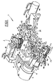
- FIGURE 1 -
- is a broken perspective view of the device according to the invention;
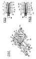
- FIGURE 2 -
- is a perspective view of an ancillary pliers system arranged in the device of the invention;
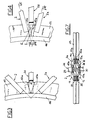
- FIGURE 3 -
- is a diagrammatic and broken lateral view of the device of the invention arranged to work on the ends of a filler applied on a bead core;
- FIGURE 4 -
- is always a diagrammatic and broken lateral view of the device according to an operative condition in which the primary pliers systems are in splicing position;
- FIGURE 5 -
- is a diagrammatic section, made along line V-V of figure 4, stressing the deformation caused on the filler by the gripping elements belonging to a first primary pliers system;
- FIGURE 6 -
- is a diagrammatic section, made along line VI-VI of figure 4, stressing the deformations caused on the filler by the gripping elements of a second primary pliers system;
- FIGURE 7 -
- shows in a diagrammatic top view the mutual arrangement of the ends of the filler prior to the intervention of an ancillary pliers system.
- With reference to the cited figures, the reference numeral 1 indicates the whole device for splicing the ends of the elastomeric fillers applied on bead cores of pneumatic tires according to the present invention.
- The device 1 comprises two
primary pliers systems collar 5 integral with a supportingframe 6, shown only in part. More particularly, an arm 3, associated to thefirst pliers system 2, is fastened to ahub 7 splined on a driving small shaft 8, while the second arm 3a is fastened to a mobile sleeve 9 engaged in a rotating manner with the stationary sleeve 4 and engaging on its turn, in a rotating manner, thehub 7 of the first arm 3. - The
primary pliers systems first pliers system 2, except for different needs. In the drawings the members of thesecond pliers system 2a will be marked with the same reference numeral as that used for the corresponding members of thefirst pliers system 2, with the addition of the suffix "a". - The first
primary pliers system 2 comprises a supportingblock 10 integral with the first arm 3 which is engaged with at least a first and asecond clamping element primary pliers system 2a. More particularly theclamping elements block 10 through respective pins 13, 14, each one integral with one end of the respective clamping element and crossing in a rotating manner the supporting block itself. - On the pin 13 belonging to the
first clamping element 11, on the part opposite to the clamping elements, a first gear wheel is splined, said gear wheel engaging when working with a second likegear wheel 16 splined on the pin 14 associated to thesecond clamping element 12. Thegear wheels clamping elements - A
control lever 17 is fastened on the pin 13 belonging to thefirst clamping element 11; a first fluid mechanics cylinder 18 mounted on the supportingblock 10 works on said control lever. Said first fluid mechanics cylinder 18 is apt to provide a mutual approaching or separation of theclamping elements clamping elements surfaces 19 havingrespective deviation portions 20 which are suitably offset with respect to the development plane of the deviation portions 20a presented by theclamping elements 11a, 12a belonging to the secondprimary pliers system 2a. - According to a preferred embodiment, the
deviation portions 20 are obtained consecutively to respective centeringportions 21 presented by the contactingsurface 19 in proximity of the free ends of thecorresponding clamping elements portions 21a belonging to thesecond pliers system 2a. As it is shown by the attached sheets of drawing, thedeviation portions 20 belonging respectively to the first andsecond clamping element corresponding centering portion 21. - Therefore, while the
deviation portions 20 of thefirst clamping element 11 forms a surface reduction with respect to thecorresponding centering portion 21, the deviation portion of thesecond clamping element 12 forms a surface relief countershaped to the above said reduction. - Of course, the geometric characteristics and the dimensional ratios between the deviation portions and the centering portions must be time by time chosen according to the type of filler on which the splicing operation has to be effected. On this purpose, it is preferably provided that the contacting
surfaces 19 are obtained oninterchangeable plates 22 releasably fastened to theclamping elements elements 23. - Always according to the present invention the device 1 is moreover provided with at least an
ancillary pliers system 24 symmetrically arranged between theprimary pliers systems second gripping element stationary pin 27 connected between a first and second supportingplate structure 6 and extending in a substantially parallel direction. - The
gripping elements surfaces 30 substantially flat, disposed coplanarly to said centeringportions interchangeable plates 31 releasably fastened to the gripping elements through threadedelements 32. - The
gripping elements respective continuations 33, 34 that, as better stressed in figure 2, diverge symmetrically when moving away from thestationary pin 27 to be rotatably engaged, at the respective free ends, withcorresponding control rods 35, 36 mutually connected by amobile pin 37. - The
mobile pin 37 is guided in a sliding manner by previous possible interposition of ball bearings or the like, through one or both the supportingplates stationary pin 27. - The
mobile pin 37 is translated along theguiding slots 38 through at least areturn plate 39 provided with ashaped opening 40 in which asmall block 41 connected on its turn to the mobile pin is guided in a sliding manner transversely of the development direction of theguiding slot 38. Thereturn plate 39 is integral with acontrol pin 42 which crosses in a rotating manner the supportingplates control lever 43; a driving fluid mechanics cylinder 44 (figure 1) connected to the first supportingplate 28 works on saidcontrol lever 43. It can be foreseen that thecontrol lever 43 is provided with a continuation 43a in the form of a plate disposed parallely to thereturn plate 39 and provided with a respective shaped opening (not shown) which, as said with reference to the opening 40, engages in a sliding manner a small block connected to themobile pin 37. - After what described in respect of the structure of the device of the invention, the working of said device is the following. The device 1 can indifferently be associated to a conventional apparatus apt to apply a
filler 45 on thebead core 46 of a pneumatic tire, or can work as an unit apart on the filler applied to the bead core during a previous processing. - Anyway, in a per se known way, the
filler 45 is in the form of a strip of elastomeric material in uncured condition with a substantially isosceles triangle section having a very accentuated height and joined at its base on the circumferential outer chafer of thebead core 46. - The
opposite ends filler 45 mutually face diverging the one from the other on moving away from the peripheral chafer of thebead core 46. More particularly theends - Always in a way known per se, the
bead core 46, provided with afiller 45 arranged as described, is positioned in such a way that the part of its circumferential development comprising theends primary pliers systems ancillary system 24. - Moreover, the positioning of the
bead core 46 takes place also in such a way that the "V" formed by theends primary pliers systems - Following the positioning of the
bead core 46 andfiller 45 associated thereto, the first fluid mechanics cylinders 18, 18a are set in action and acting on the respective control levers 17, 17a rotate angularly thecorresponding clamping elements elements filler 45, to a closing position where, as shown with a continuous line in the above said figures, they work against the opposite ends of the filler itself exerting opposed thrust forces. - As shown in the figures 5 and 6, when the clamping
elements portions surfaces 20 work on a circumferential inner zone "I" of thefiller 45, so that the positioning of said zones is maintained symmetric with respect to the development median plane of thebead core 46. Thedeviation portions 20 and 20a work on a circumferential outer zone "E" of the filler so as to move it lightly away with respect to the development median plane of thebead core 46. It has to be noted that thedeviation portions 20 and 20a belonging respectively to the first andsecond pliers systems - While the
ends elements pliers systems 2a and 2b from a rest position where, as shown in figure 3, are mutually spaced for permitting the engagement of thefiller 45 by the clamping elements themselves, to an operative position in which, as shown in figure 4, the pliers systems are mutually approached to splice theends - Advantageously, the pivoting axis of the arms 3 and 4, namely the axis around which the
primary pliers systems ends - Preferably, the above axis of rotation results lightly moved toward the center of the bead core with respect to the converging point of the "V". Originally, on translating from the rest position to the splicing position the
primary pliers systems ends filler 45 by the clampingelements pliers systems - At this point the
ancillary pliers system 24 is set in action through the drivingfluid mechanics cylinder 44. - More particularly, the
stem 44a of thefluid mechanics cylinder 44 is removed from the cylinder itself to cause, through thecontrol pin 42, a rotation of thereturn plate 39 according to the direction of the arrow A of figure 2. Following said rotation, themobile pin 37 is moved along the guidingslots 38 toward thestationary pin 27, determining through thecontrol rods 35, 36 a mutual spreading out of thecontinuations 33 and 34 presented by thegripping elements gripping elements ends surfaces 30 of thegripping elements - In this situation, since the elastomeric material constituting the
filler 45 is still uncured, a perfect splicing between theends - The present invention achieves thus the aimed purposes.
- The fact of placing the ends of the filler side by side in the circumferential outer zones of this latter, solves the problem given in the known technique by the difficulty of butt-splicing the ends themselves in the zones farther from the bead cores, where the filler has a very limited thickness.
- Moreover, the lateral compression made on the ends of the filler by the ancillary pliers system eliminates the drawbacks given, in the known technique, by the unavoidable expansion of the filler section at the splicing zone.
Claims (7)
- Device for splicing the ends of elastomeric fillers applied on bead cores (46) of pneumatic tires, said filler (45) extending along a circumferential outer chafer of a bead core (46) and having its own ends (45a, 45b) mutually faced diverging the one with respect to the other on moving away from the peripheral chafer of the bead core according to a substantially "V" configuration, said device comprising two primary pliers systems (2,2a), each one working on one of the opposed ends (45a, 45b) of the filler (45) through at least two faced gripping elements (25, 26) placed on opposite parts at the side of the filler (45) and mobile the one with respect to the other from an opening position, in which they are laterally separated by the filler (45) to a closing position in which they work against the opposite sides of the filler exerting opposed thrust forces, said primary pliers system (2, 2a) being angularly mobile around an axis of rotation near the point in which the "V" configuration of the filler ends converges to be led from a rest position in which they are mutually separated to permit the locking of the filler ends (45a, 45b) between said gripping elements to a splicing position in which they are mutually approached to splice said ends (45a, 45b) when these latter are held by the gripping elements (25, 26) in closing position, characterized by the fact that said primary pliers systems (2, 2a), on translating from the rest position to the splicing position, rotate the one with respect to the other according to an angulation greater than the angle formed by the "V" configuration of the filler ends (45a, 45b) when the pliers systems themselves are in rest position, and by the fact that the clamping means (11, 12; 11a, 12a) of each pliers system (2, 2a) work on the filler through respective contacting surfaces (19) having respective deviation portions (20) which are offset with respect to the deviation portions (20a) of the contacting surfaces belonging to the other primary pliers system and are suitable for acting on a circumferential outer zone of the filler to mutually place side by side the ends of this latter at said circumferential outer zone in consequence of the translation of the pliers system in the splicing position, said device comprising also at least an ancillary pliers system (24) arranged between said primary pliers system and provided with respective gripping elements (25, 26) symmetrically placed side by side with respect to the opposite sides of the filler and mobile for a mutual approaching to compress the ends of the filler mutually brought near by the action of the primary pliers systems.
- Device according to claim 1, characterized by the fact that the deviation portions (20, 20a) presented by the gripping elements of each primary pliers system are obtained consecutively to respective centering portions (21, 21a) presented by said contacting surfaces (19) and arranged at the free ends of the clamping elements, coplanarly to the centering portions presented by the clamping elements of the other primary pliers system.
- Device according to claim 1, characterized by the fact that the axis of rotation of the primary pliers systems (2, 2a) is lightly moved toward the center of the bead core with respect to the point in which the "V" configuration presented by the free ends of the filler converges.
- Device according to claim 1, characterized by the fact that each primary pliers system (2) comprises a supporting block (10) integral with an arm (3) pivoted in a rotating manner according to said axis of rotation, a pair of pins (13, 14) rotatably crossing the supporting block and engaging the clamping elements (11, 12) on the part turned toward the other primary pliers system (2a), two gear wheels (15, 16) each one engaged on one of said pins on the part opposite to the clamping elements and operatively engaged between one another, a control level (17) integral with one of said pins and a fluid mechanics cylinder(18) mounted on the supporting block (10) and operating on said control level (17) to provide the mutual approaching and separation of the clamping elements.
- Device according to claim 1, characterized by the fact that said primary pliers systems (2, 2a) are respectively supported by a first arm (3) integral with a hub (7) splined on a driving small shaft and by a second arm (3a) integral with a mobile sleeve (9) rotatably engaging said hub and rotatably engaging itself with a stationary sleeve (4) rigidly connected to a supporting structure.
- Device according to claim 1, characterized by the fact that said ancillary pliers system (24) comprises a stationary pin (27) mounted between a first and second supporting plate (28, 29) and rotatably engaging said gripping elements (25, 26), a pair of control rods (35, 36) each one rotatably engaged with a continuation (33, 34) of one of said gripping elements and a mobile pin (37) engaging the control rod and engaged in a sliding manner along at least a guiding slot (38) obtained in one of said supporting plate (28) and extending according to the axis of alignment between the mobile pin and the stationary pin, said mobile pin (37) being translable along said guiding slots to provide the mutual approaching and separation of the gripping elements in consequence of the action of said control rods.
- Device according to claim 6, characterized by the fact that said mobile pin (37) is translable in consequence of the action of a return plate (39) provided with a shaped opening in which a control small block (41) engaging the mobile pin is encased in a sliding manner within a direction transversal to the development direction of the guiding slots, said return plate (39) being integral with a control pin (42) rotatably crossing the supporting plate (28, 29) and rigidly engaging, on the part opposite to the return plate, a control lever (43) on which a fluid mechanics cylinder (44) engaged with one of said supporting plates works.
Applications Claiming Priority (2)
| Application Number | Priority Date | Filing Date | Title |
|---|---|---|---|
| IT2062188 | 1988-05-18 | ||
| IT20621/88A IT1217631B (en) | 1988-05-18 | 1988-05-18 | DEVICE FOR JOINING THE ENDS OF ELASTOMERIC FILLERS APPLIED TO TIRES |
Publications (3)
| Publication Number | Publication Date |
|---|---|
| EP0342467A2 EP0342467A2 (en) | 1989-11-23 |
| EP0342467A3 EP0342467A3 (en) | 1991-11-06 |
| EP0342467B1 true EP0342467B1 (en) | 1993-06-09 |
Family
ID=11169677
Family Applications (1)
| Application Number | Title | Priority Date | Filing Date |
|---|---|---|---|
| EP89108236A Expired - Lifetime EP0342467B1 (en) | 1988-05-18 | 1989-05-08 | Device for splicing the ends of elastomeric fillers applied on bead cores of pneumatic tires |
Country Status (6)
| Country | Link |
|---|---|
| US (2) | US4994136A (en) |
| EP (1) | EP0342467B1 (en) |
| JP (1) | JP2667905B2 (en) |
| AR (1) | AR241877A1 (en) |
| DE (1) | DE68906958T2 (en) |
| IT (1) | IT1217631B (en) |
Families Citing this family (14)
| Publication number | Priority date | Publication date | Assignee | Title |
|---|---|---|---|---|
| US5221409A (en) * | 1992-01-06 | 1993-06-22 | The Goodyear Tire & Rubber Company | Apparatus for butt splicing ply stock |
| JP2524059B2 (en) * | 1992-09-29 | 1996-08-14 | 住友ゴム工業株式会社 | Bead-apex automatic assembling method and apparatus |
| AU6946900A (en) * | 1999-09-03 | 2001-04-10 | Bartell Machinery Systems, Llc | Apparatus for stitching and seaming elastomeric fillers to tire beads |
| JP4501265B2 (en) * | 2000-09-25 | 2010-07-14 | 横浜ゴム株式会社 | Bead filler crimping method and apparatus |
| JP2006186318A (en) * | 2004-11-30 | 2006-07-13 | Nidec Tosok Corp | Lead frame extrusion equipment |
| WO2008010293A1 (en) | 2006-07-21 | 2008-01-24 | Toyo Tire & Rubber Co., Ltd. | Method and device for producing tire bead |
| KR101015917B1 (en) * | 2008-12-04 | 2011-02-23 | 한국타이어 주식회사 | Side peeling tape attachment device attached to carcass fabric at tire cutting equipment |
| FR2953444B1 (en) * | 2009-12-09 | 2012-01-13 | Michelin Soc Tech | METHOD FOR MANUFACTURING A RING FOR CARRYING OUT A TIRE |
| NL2009946C2 (en) | 2012-12-10 | 2014-06-11 | Vmi Holland Bv | Tyre building machine for forming a bead-apex assembly. |
| NL2010201C2 (en) * | 2013-01-30 | 2014-08-04 | Vmi Holland Bv | Apparatus for forming an annular apex filler. |
| JP6228221B2 (en) * | 2013-10-03 | 2017-11-08 | 不二精工株式会社 | Method and apparatus for mounting filler on bead core |
| CN105682908B (en) * | 2013-10-18 | 2019-11-05 | 巴特尔机械系统有限责任公司 | System and method for gripping and handling tire bead apex |
| US10688745B2 (en) * | 2014-03-24 | 2020-06-23 | Fuji Seiko Co., Ltd. | Winding method and winding device for bead filler for tire |
| NL2027901B1 (en) * | 2021-04-01 | 2022-10-17 | Vmi Holland Bv | Method for positioning a strip for splicing, gripper for supplying said strip for splicing and tire building machine comprising said gripper |
Family Cites Families (15)
| Publication number | Priority date | Publication date | Assignee | Title |
|---|---|---|---|---|
| US2309305A (en) * | 1941-03-10 | 1943-01-26 | Carborundum Co | Abrasive article |
| US2565703A (en) * | 1948-05-22 | 1951-08-28 | Goodrich Co B F | Apparatus for splicing cushion tires |
| US2497461A (en) * | 1949-04-19 | 1950-02-14 | Dunlop Tire & Rubber Corp | Apparatus for splicing inner tubes of tires |
| US2647555A (en) * | 1950-12-12 | 1953-08-04 | Us Rubber Co | Method and apparatus for splicing |
| US2679888A (en) * | 1953-02-06 | 1954-06-01 | William K Bohon | Belt splicer |
| US3026569A (en) * | 1959-02-16 | 1962-03-27 | Philip B Keller | Method of fabricating omicron-rings |
| NL6802950A (en) * | 1968-03-01 | 1969-09-03 | ||
| US3976534A (en) * | 1973-07-28 | 1976-08-24 | Howaldtswerke-Deutsche Werft Aktiengesellschaft Hamburg Und Kiel | Device for use in uniting the adjacent ends of radially split sealing rings |
| IT1115688B (en) * | 1977-12-15 | 1986-02-03 | Pirelli | DEVICE FOR THE APPLICATION OF AN ELASTOMERIC FILLER TO A TIRE RIM |
| IT1094441B (en) * | 1978-04-19 | 1985-08-02 | Pirelli | IMPROVEMENTS WITH TIRE CIRCLE ELASTOMERIC FILLER APPLICATOR |
| IT1124588B (en) * | 1979-10-09 | 1986-05-07 | Pirelli | IMPROVEMENTS IN EQUIPMENT FOR THE APPLICATION OF ELASTOMERIC FILLERS IN TIRES |
| US4452660A (en) * | 1982-09-27 | 1984-06-05 | The Goodyear Tire & Rubber Company | Bead jamming or crimping apparatus |
| US4484975A (en) * | 1984-01-23 | 1984-11-27 | Mcelroy Manufacturing, Inc. | Hand held apparatus for joining small diameter plastic pipe |
| JPS6490736A (en) * | 1987-09-30 | 1989-04-07 | Sumitomo Rubber Ind | Apex mounting and its device |
| US5006385A (en) * | 1988-07-22 | 1991-04-09 | Signode Corporation | Strapping joint and method for forming same |
-
1988
- 1988-05-18 IT IT20621/88A patent/IT1217631B/en active
-
1989
- 1989-05-01 US US07/345,299 patent/US4994136A/en not_active Expired - Lifetime
- 1989-05-08 DE DE89108236T patent/DE68906958T2/en not_active Expired - Lifetime
- 1989-05-08 EP EP89108236A patent/EP0342467B1/en not_active Expired - Lifetime
- 1989-05-16 AR AR89313932A patent/AR241877A1/en active
- 1989-05-18 JP JP1125478A patent/JP2667905B2/en not_active Expired - Fee Related
-
1990
- 1990-12-27 US US07/634,715 patent/US5133817A/en not_active Expired - Lifetime
Also Published As
| Publication number | Publication date |
|---|---|
| EP0342467A3 (en) | 1991-11-06 |
| JPH0220331A (en) | 1990-01-23 |
| IT8820621A0 (en) | 1988-05-18 |
| AR241877A1 (en) | 1993-01-29 |
| EP0342467A2 (en) | 1989-11-23 |
| JP2667905B2 (en) | 1997-10-27 |
| US5133817A (en) | 1992-07-28 |
| US4994136A (en) | 1991-02-19 |
| DE68906958T2 (en) | 1994-01-20 |
| IT1217631B (en) | 1990-03-30 |
| DE68906958D1 (en) | 1993-07-15 |
Similar Documents
| Publication | Publication Date | Title |
|---|---|---|
| EP0342467B1 (en) | Device for splicing the ends of elastomeric fillers applied on bead cores of pneumatic tires | |
| US3674604A (en) | Tire building drum | |
| US7735535B2 (en) | Shaping and laying a tire belt ply | |
| IE40287B1 (en) | Improvements in or relating to a method and apparatus for producing a cowtinuous band of rubberised fabric | |
| US5466182A (en) | Machine for scraping tires with controllable relative positioning of tire and work tool | |
| US7402221B2 (en) | Method for pressure bonding of a breaker-tread assembly with a carcass assembly by means of stitching in the manufacture of green tyres and device for accomplishment of such method | |
| JP2579530B2 (en) | Hemming molding method | |
| EP0345633B1 (en) | Device for applying an elastomeric filler on the bead core of a pneumatic tire | |
| US3332820A (en) | Band support | |
| US4584049A (en) | Radial tire forming blank supply apparatus | |
| GB1597199A (en) | Device for the application of elastomeric fillers on bead cores of pneumatic tyres | |
| EP0405350A1 (en) | Adjustable tire recapping apparatus | |
| US4565084A (en) | Method and a tool for bending the edge of thick sheet metal | |
| JP3583172B2 (en) | Automotive wheel tire fitting device | |
| US2489324A (en) | Splicing apparatus | |
| US5379667A (en) | Pinch cutting method and apparatus | |
| US2510715A (en) | Curing bag splicing machine | |
| JPH03218818A (en) | Tread sticking method for tire forming machine | |
| JPH0140630Y2 (en) | ||
| US2971563A (en) | Method and apparatus for applying tread to rubber tires | |
| US4670082A (en) | Machine for retreading pneumatic tires | |
| US4682641A (en) | System for manufacture of high-lug tires | |
| CN121245326B (en) | A steel structure welding equipment and welding process | |
| CA1313349C (en) | Apparatus for mounting and dismounting of tyres | |
| JPS6337243Y2 (en) |
Legal Events
| Date | Code | Title | Description |
|---|---|---|---|
| PUAI | Public reference made under article 153(3) epc to a published international application that has entered the european phase |
Free format text: ORIGINAL CODE: 0009012 |
|
| AK | Designated contracting states |
Kind code of ref document: A2 Designated state(s): DE FR GB |
|
| PUAL | Search report despatched |
Free format text: ORIGINAL CODE: 0009013 |
|
| AK | Designated contracting states |
Kind code of ref document: A3 Designated state(s): DE FR GB |
|
| 17P | Request for examination filed |
Effective date: 19920416 |
|
| 17Q | First examination report despatched |
Effective date: 19921027 |
|
| GRAA | (expected) grant |
Free format text: ORIGINAL CODE: 0009210 |
|
| AK | Designated contracting states |
Kind code of ref document: B1 Designated state(s): DE FR GB |
|
| REF | Corresponds to: |
Ref document number: 68906958 Country of ref document: DE Date of ref document: 19930715 |
|
| ET | Fr: translation filed | ||
| PLBE | No opposition filed within time limit |
Free format text: ORIGINAL CODE: 0009261 |
|
| STAA | Information on the status of an ep patent application or granted ep patent |
Free format text: STATUS: NO OPPOSITION FILED WITHIN TIME LIMIT |
|
| 26N | No opposition filed | ||
| REG | Reference to a national code |
Ref country code: GB Ref legal event code: IF02 |
|
| PGFP | Annual fee paid to national office [announced via postgrant information from national office to epo] |
Ref country code: FR Payment date: 20060517 Year of fee payment: 18 |
|
| PGFP | Annual fee paid to national office [announced via postgrant information from national office to epo] |
Ref country code: GB Payment date: 20060525 Year of fee payment: 18 |
|
| GBPC | Gb: european patent ceased through non-payment of renewal fee |
Effective date: 20070508 |
|
| REG | Reference to a national code |
Ref country code: FR Ref legal event code: ST Effective date: 20080131 |
|
| PG25 | Lapsed in a contracting state [announced via postgrant information from national office to epo] |
Ref country code: GB Free format text: LAPSE BECAUSE OF NON-PAYMENT OF DUE FEES Effective date: 20070508 |
|
| PG25 | Lapsed in a contracting state [announced via postgrant information from national office to epo] |
Ref country code: FR Free format text: LAPSE BECAUSE OF NON-PAYMENT OF DUE FEES Effective date: 20070531 |
|
| PGFP | Annual fee paid to national office [announced via postgrant information from national office to epo] |
Ref country code: DE Payment date: 20080630 Year of fee payment: 20 |