EP0342412B1 - Motorically adjustable rear view mirror - Google Patents
Motorically adjustable rear view mirror Download PDFInfo
- Publication number
- EP0342412B1 EP0342412B1 EP89107726A EP89107726A EP0342412B1 EP 0342412 B1 EP0342412 B1 EP 0342412B1 EP 89107726 A EP89107726 A EP 89107726A EP 89107726 A EP89107726 A EP 89107726A EP 0342412 B1 EP0342412 B1 EP 0342412B1
- Authority
- EP
- European Patent Office
- Prior art keywords
- rear view
- view mirror
- housing
- bearing
- base plate
- Prior art date
- Legal status (The legal status is an assumption and is not a legal conclusion. Google has not performed a legal analysis and makes no representation as to the accuracy of the status listed.)
- Expired - Lifetime
Links
Images


Classifications
-
- B—PERFORMING OPERATIONS; TRANSPORTING
- B60—VEHICLES IN GENERAL
- B60R—VEHICLES, VEHICLE FITTINGS, OR VEHICLE PARTS, NOT OTHERWISE PROVIDED FOR
- B60R1/00—Optical viewing arrangements; Real-time viewing arrangements for drivers or passengers using optical image capturing systems, e.g. cameras or video systems specially adapted for use in or on vehicles
- B60R1/02—Rear-view mirror arrangements
- B60R1/06—Rear-view mirror arrangements mounted on vehicle exterior
- B60R1/0605—Rear-view mirror arrangements mounted on vehicle exterior specially adapted for mounting on trucks, e.g. by C-shaped support means
- B60R1/0607—Rear-view mirror arrangements mounted on vehicle exterior specially adapted for mounting on trucks, e.g. by C-shaped support means with remote position control adjustment
- B60R1/0612—Rear-view mirror arrangements mounted on vehicle exterior specially adapted for mounting on trucks, e.g. by C-shaped support means with remote position control adjustment by electrically actuated means
Definitions
- the invention relates to a motor-adjustable rear-view mirror for motor vehicles, in particular trucks, according to the preamble of patent claim 1.
- actuators are attached to a base plate which is firmly connected to the fastening device.
- the actuator of the one actuator acts directly on the housing and pivots the housing about a transverse axis of a universal joint which is arranged between the housing and the base plate.
- the other actuator engages the universal joint and pivots the housing around its longitudinal axis.
- the installation depth of the servomotor arrangement is relatively large, so that the housing in turn becomes so deep that the driver's field of vision in the direction obliquely towards the front is considerably restricted, which is important when maneuvering, in which a very exact use of space is required proves disadvantageous.
- the sliding crank mechanism is provided with a crank between the actuators fixedly attached to the housing and the base element which is fixed relative to the fastening device of the rear view mirror and which is coupled to the base element via a sliding bearing.
- the sliding bearing is formed by a pin on the crank of the actuators, which engages in an elongated hole guide of a separate guide part rotatably mounted in the base element.
- the disadvantage of this construction is that the thrust crank mechanism is designed to be relatively space-consuming, can only be assembled in a complex manner due to the necessary rotary mounting of the guide part, and is quite unstable in itself due to the elongated hole guide.
- the invention has for its object to design a rear view mirror of the generic type so that it has the simplest possible structure, easy to assemble and a flat very stable design.
- the configuration according to the invention allows an extremely flat design.
- the thrust crank gear designed according to the invention the forces required for pivoting the housing with the mirror glass pane relative to the fastening device are transmitted transversely to the longitudinal direction of the thrust crank gear on the base plate, in that a push rod is articulated on the crank by means of a crank joint which can be displaced in a bearing sleeve connected to the base plate is led.
- the thrust crank mechanism is pivotable about a longitudinal axis of the sliding bearing, then it is ensured that, on the one hand, installation inaccuracies of the actuators and of the thrust crank mechanism are of no importance. This also ensures that when two actuators are used, each sliding crank gear can accommodate the pivoting movements generated by the other actuator.
- the housing can be pivoted about a center point about a universal joint connected to the fastening device.
- This configuration allows a further advantageous development, according to which the pivot axis assigned to each actuator runs through the center of the universal joint. This ensures that an extremely flat design is achieved. This is further achieved in that each actuator is attached directly to the housing.
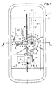
- the rear view mirror for trucks shown in FIGS. 1 and 2 has a housing 1 with a glass receptacle 2, in which a curved mirror glass pane 3 is held interchangeably by means of a retaining ring 4.
- the frame-like glass receptacle 2 delimits the largest cross-sectional area of the housing 1 when the mirror glass pane 3 is removed.
- the glass receptacle 2 is approximately rectangular, corresponding to the cross-sectional area of the mirror glass pane 3.
- the area delimited by it has two mutually perpendicular axes of symmetry 5, 6, one axis of symmetry 5 being significantly longer than the axis of symmetry 6. In practice, the axis of symmetry 5 is approximately twice as long as the axis of symmetry 6.
- the rearview mirror has a fastening device 7 in the manner of a tripod clamp, by means of which a clamping fastening to a rod 8 of a fastening bracket is possible.
- a fastening device 7 in the manner of a tripod clamp, by means of which a clamping fastening to a rod 8 of a fastening bracket is possible.
- Such an L- or C-shaped mounting bracket is attached to the side of the cab of a truck, as is common in practice.
- the rod 8 is arranged essentially vertically. Its axis 9 runs essentially parallel to the long axis of symmetry 5.
- the fastening device 7 has two clamping jaws 10, 11 resting on the rod 8, which are held together by means of screws 12 and hold the rod 8 in a clamping manner between them. When the screws 12 are loosened, the rearview mirror can be displaced in the direction of the axis 9 on the rod 8 and pivoted about the rod 8.
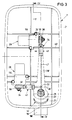
- One jaw 11 is formed in one piece with a bearing body 13 of a universal joint 14 designed in the manner of a spherical bearing.
- a concave spherical bearing shell 16 is formed on this bearing body 13 symmetrically with respect to its central axis 15.
- the housing 1 is provided with a recess, ie it has an approximately frustoconical wall region 17 directed into the interior of the housing 1, on the bottom of which a bearing part 18 is formed with two parallel bearing surfaces 19, 20.
- the outer bearing surface 19 of these two bearing surfaces 19, 20 lies against the bearing shell 16.
- a spherical bearing cover 21 bears against the inner bearing surface 20.
- the bearing surfaces 19, 20 and the bearing shell 16 and the bearing cover 21 have a common spherical center 22, which lies on the central axis 15.
- the bearing cap 21 is against the by means of a preloaded helical compression spring 23 Bearing part 18 and thus pressed against the bearing shell 16, so that the bearing part 18 is held with its bearing surfaces 19, 20 between the bearing shell 16 and the bearing cap 21 with a predetermined frictional force.
- the compression spring 23 is supported on its side opposite the bearing cover 21 against a cover-like abutment 24.
- the package consisting of bearing body 13 with bearing shell 16, bearing part 18, bearing cover 21, compression spring 23 and abutment 24 is held together by a threaded bolt 25 aligned with the central axis 15 with a screwed-on threaded nut 26.
- Attached to the housing 1 are two electromotive actuators 28, 29, each of which consists of an electric motor 30 and a reduction gear 31 arranged downstream thereof.
- the output axes 32, 33 of these two actuators 28, 29 are arranged perpendicular to one another, with one output axis 32 and 33 respectively running parallel to one of the axes of symmetry 5 and 6.
- a thrust crank gear 34 is attached, which consists of a crank 35 driven by the respective output axis 32 or 33 and a connecting rod 37 connected to it via a crank joint 36.
- the respective thrust crank mechanism 34 ie specifically the crank 35, is connected to the respective output axis 32 or 33 via a slip clutch 38 which is only indicated in the drawing.
- a base plate 39 designed in the manner of an angle lever is fastened to the universal joint 14 of the fastening device 7 and is supported with respect to the bearing body 13 by means of the threaded bolt 25 with a threaded nut 26 via a spacer sleeve 40.
- the cover-like abutment 24 is also supported against this spacer sleeve 40.
- the base plate 39 is thus firmly connected to the fastening device 7.
- the base plate 39 has two cylindrical bearing sleeves 41, into which the likewise cylindrical push rods 37 of the push crank mechanism 34 of the two actuators 28, 29 engage.
- sliding bearings 42, 43 are formed.
- forces acting in the direction of the respective axis 44 of the corresponding push rod 37 cannot be transmitted, while forces acting perpendicularly thereto can be transmitted from the push crank mechanism 34 to the base plate 39.
- the housing 1 becomes relative to the fastening device 7 pivoted.
- the bearing part 18 with its two bearing surfaces 19, 20 is displaced between the bearing shell 16 and the bearing cover 21 while overcoming the above-described frictional force.
- the pivoting movements of the housing 1 take place about two pivot axes 47, 48 which are perpendicular to one another and pass through the center point 22 of the ball, namely about the pivot axis 47 when the actuator 28 is actuated and about the pivot axis 48 when the actuator 29 is actuated.
- the pivot axis 47 extends parallel to the output axis 32; the pivot axis 48 runs parallel to the output axis 33.
- a socket 53 is attached in the housing 1, from which electrical lines 54, 55 lead to the electric motors 30 of the two actuators 28, 29.
- the actuation switches for the actuators 28, 29 are located in the motor vehicle and are therefore not shown.
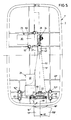
- FIGS. 3 and 4 differs from that according to FIGS. 1 and 2 essentially by the arrangement of a fastening device 7 'and thus the universal joint 14' relative to the housing 1 '. Since all essential parts are identical or at least functionally the same as the corresponding parts of the embodiment according to FIGS. 1 and 2, the same reference numerals are used for identical parts and the same reference numbers are used for structurally modified but functionally identical parts with a prime, without it being detailed each requires a new description.
- the fastening device 7 ' may have a holding arm 58 leading directly to the truck.
- the fastening device 7 ' has no threaded bolt; rather, on the spacer sleeve 40 ', a cover-like abutment 24' is formed through the threaded sleeve extension 60, onto which the threaded nut 26 is screwed. This makes it possible to introduce a power supply cable 61 for the actuators 28, 29 into the housing 1 'through the spacer sleeve 40'.
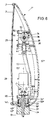
- the lower outer transverse wall 56 ′′ has the spherical bearing part 18 ′′.
- a base plate 62 in the manner of a simple lever is fixedly attached to the universal joint 14 ′′, on which an actuator 29 engages by means of a sliding crank mechanism 34 via a sliding bearing 43.
- the base plate 62 can be rotated about the central axis 15 ′′, which is so far serves as a pivot axis 15 ".
- An actuator 28 is fastened to the housing 1" by means of a holding plate 63 and screws 52 ", on the output axis 32 of which a toothed pinion 64 is fastened, which is rotatably connected to the spacer sleeve 40" and above it to the bearing body 13 " connected gear 65.
- the pinion 64 and the gear 65 form a pinion 66.
- the actuator 1 is rotated relative to the holding arm 58 "by a corresponding drive of the actuator 28 about its output axis 32 parallel to the central axis 15".
- the pivoting movement perpendicular to this that is to say about a horizontal pivot axis in FIGS. 5 and 6, takes place by means of the actuator 29.
Description
Die Erfindung betrifft einen motorisch verstellbaren Rückspiegel für Kraftfahrzeuge, insbesondere Lastkraftwagen, nach dem Oberbegriff des Patentanspruches 1.The invention relates to a motor-adjustable rear-view mirror for motor vehicles, in particular trucks, according to the preamble of
Bei einem aus der DE-B-28 22 681 (entsprechend FR-A-24 26 590 und SE-A-79 04 338) bekannten Rückspiegel sind an einer fest mit der Befestigungseinrichtung verbundenen Grundplatte Stellantriebe angebracht. Das Stellglied des einen Stellantriebes greift unmittelbar am Gehäuse an und verschwenkt das Gehäuse um eine Querachse eines Kreuzgelenks, das zwischen dem Gehäuse und der Grundplatte angeordnet ist. Der andere Stellantrieb greift am Kreuzgelenk an und verschwenkt so das Gehäuse um seine Längsachse. Dieser bekannte Spiegel ist konstruktiv umständlich aufgebaut, so daß die Montage sehr aufwendig ist. Weiterhin ist die Einbautiefe der Stellmotor-Anordnung verhältnismäßig groß, so daß das Gehäuse wiederum so tief wird, daß das Blickfeld des Fahrers in Richtung schräg nach vorn erheblich eingeschränkt wird, was sich bei Rangiermanövern, bei welchen es auf eine sehr exakte Platzausnutzung ankommt, als nachteilig erweist.In the case of a rear-view mirror known from DE-B-28 22 681 (corresponding to FR-
Aus der EP-A-0 090 909 ist es zur Lösung des letztgenannten Problems für motorisch verstellbare Rückspiegel bereits bekannt, die Stellmotor-Anordnung unmittelbar mit der Befestigungseinrichtung zu verbinden. Diese bekannte Ausgestaltung führt aber nicht zu einer ausreichend stabilen Verbindung zwischen Gehäuse und Befestigungseinrichtung, soweit es sich um besonders große Rückspiegel handelt.From EP-A-0 090 909 it is already known to solve the latter problem for motor-driven rear-view mirrors to connect the servomotor arrangement directly to the fastening device. However, this known configuration does not lead to a sufficiently stable connection between the housing and the fastening device, insofar as the mirrors are particularly large.
Aus der JP-A-62 152 942 ist ein motorisch verstellbarer Rückspiegel für Kraftfahrzeuge mit den im Oberbegriff des Patentanspruches 1 angegebenen Merkmalen bekannt. Dabei ist das Schubkurbelgetriebe zwischen den ortsfest am Gehäuse befestigten Stellantrieben und der relativ zur Befestigungseinrichtung des Rückspiegels ortsfest angeordneten Grundelement mit einer Kurbel versehen, die mit dem Grundelement über ein Schiebelager gekoppelt ist. Das Schiebelager ist durch einen Stift an der Kurbel der Stellantriebe gebildet, der in eine Langlochführung eines gesonderten, drehbar im Grundelement gelagerten Führungsteil eingreift.From JP-A-62 152 942 a motorized rear-view mirror for motor vehicles with the features specified in the preamble of
Nachteilig bei dieser Konstruktion ist, daß das Schubkurbelgetriebe relativ platzaufwendig gestaltet, aufgrund der notwendigen Drehlagerung des Führungsteils nur aufwendig montierbar und aufgrund der Langlochführung in sich recht instabil ist.The disadvantage of this construction is that the thrust crank mechanism is designed to be relatively space-consuming, can only be assembled in a complex manner due to the necessary rotary mounting of the guide part, and is quite unstable in itself due to the elongated hole guide.
Der Erfindung liegt die Aufgabe zugrunde, einen Rückspiegel der gattungsgemäßen Art so auszugestalten, daß er einen möglichst einfachen Aufbau, eine einfache Montierbarkeit und eine flache sehr stabile Ausgestaltung aufweist.The invention has for its object to design a rear view mirror of the generic type so that it has the simplest possible structure, easy to assemble and a flat very stable design.
Diese Aufgabe wird durch die im kennzeichnungsteil des Anspruches 1 angegebenen Merkmale gelöst. Die erfindungsgemäße Ausgestaltung erlaubt eine außerordentlich flache Bauweise. Durch das erfindungsgemäß ausgestaltete Schubkurbelgetriebe werden die zum Verschwenken des Gehäuses mit der Spiegelglasscheibe relativ zur Befestigungseinrichtung erforderlichen Kräfte quer zur Längsrichtung der Schubkurbelgetriebe auf die Grundplatte übertragen, indem an der Kurbel eine Schubstange mittels eines Kurbelgelenks angelenkt ist, die in einer mit der Grundplatte verbundenen Lagerhülse verschiebbar geführt ist.This object is achieved by the features specified in the characterizing part of
Wenn gemäß einer weiteren vorteilhaften Ausgestaltung vorgesehen ist, daß das Schubkurbelgetriebe in sich um eine Längsachse des Schiebelagers schwenkbar ist, dann ist sichergestellt, daß einerseits Einbauungenauigkeiten der Stellantriebe und der Schubkurbelgetriebe ohne Bedeutung sind. Weiterhin ist hierdurch sichergestellt, daß bei Einsatz von zwei Stellantrieben jedes Schubkurbelgetriebe die vom jeweils anderen Stellantrieb erzeugten Schwenkbewegungen aufnehmen kann.If, according to a further advantageous embodiment, it is provided that the thrust crank mechanism is pivotable about a longitudinal axis of the sliding bearing, then it is ensured that, on the one hand, installation inaccuracies of the actuators and of the thrust crank mechanism are of no importance. This also ensures that when two actuators are used, each sliding crank gear can accommodate the pivoting movements generated by the other actuator.
Es ist von ganz besonderem Vorteil, wenn das Gehäuse um ein mit der Befestigungseinrichtung verbundenes Universal-Gelenk um einen Mittelpunkt schwenkbar ist. Diese Ausgestaltung erlaubt eine weitere vorteilhafte Weiterbildung, wonach die jedem Stellantrieb zugeordnete Schwenkachse durch den Mittelpunkt des Universal-Gelenks verläuft. Hierdurch ist sichergestellt, daß eine extrem flache Bauweise erreicht wird. Dies wird noch weiter dadurch erreicht, daß jeder Stellantrieb unmittelbar am Gehäuse befestigt ist.It is particularly advantageous if the housing can be pivoted about a center point about a universal joint connected to the fastening device. This configuration allows a further advantageous development, according to which the pivot axis assigned to each actuator runs through the center of the universal joint. This ensures that an extremely flat design is achieved. This is further achieved in that each actuator is attached directly to the housing.
Grundsätzlich ist es möglich, nur einen Stellantrieb vorzusehen; von besonderem Vorteil ist es aber, wenn zwei Stellantriebe vorgesehen sind. Hierbei kann es einerseits besonders vorteilhaft sein, wenn beide Stellantriebe jeweils über ein Schubkurbelgetriebe mit der Grundplatte gekoppelt sind. Andererseits kann es aber auch zweckmäßig sein, wenn ein Stellantrieb über ein Schubkurbelgetriebe mit der Grundplatte gekoppelt ist und daß der andere Stellantrieb mit der Grundplatte über einen Zahntrieb gekoppelt ist.Basically, it is possible to provide only one actuator; However, it is particularly advantageous if two actuators are provided. On the one hand, it can be particularly advantageous if both actuators each have a thrust crank mechanism the base plate are coupled. On the other hand, however, it can also be expedient if one actuator is coupled to the base plate via a sliding crank mechanism and that the other actuator is coupled to the base plate via a pinion.
Weitere Vorteile und Merkmale ergeben sich aus der nachfolgenden Beschreibung von Ausführungsbeispielen anhand der Zeichnung. Es zeigt
- Fig. 1
- eine erste Ausführungsform eines Rückspiegels gemäß der Erfindung in Draufsicht mit abgenommener Spiegelglasscheibe,
- Fig. 2
- einen Querschnitt durch den Rückspiegel gemäß der Schnittlinie II-II in Fig. 1,
- Fig. 3
- eine zweite Ausführungsform eines erfindungsgemäßen Rückspiegels in Draufsicht bei herausgenommener Spiegelglasscheibe,
- Fig. 4
- einen Querschnitt durch die zweite Ausführungsform gemäß der Schnittlinie IV-IV in Fig. 3,
- Fig. 5
- eine dritte Ausführungsform eines erfindungsgemäßen Rückspiegels in Draufsicht bei herausgenommener Spiegelglasscheibe, und
- Fig. 6
- einen Querschnitt durch die dritte Ausführungsform gemäß der Schnittlinie VI-VI in Fig. 5.
- Fig. 1
- 1 shows a first embodiment of a rearview mirror according to the invention in plan view with the mirror glass pane removed,
- Fig. 2
- 2 shows a cross section through the rearview mirror according to section line II-II in FIG. 1,
- Fig. 3
- a second embodiment of a rearview mirror according to the invention in plan view with the mirror glass pane removed,
- Fig. 4
- 3 shows a cross section through the second embodiment according to section line IV-IV in FIG. 3,
- Fig. 5
- a third embodiment of a rear view mirror according to the invention in plan view with the mirror glass pane removed, and
- Fig. 6
- 5 shows a cross section through the third embodiment according to the section line VI-VI in FIG. 5.
Der in den Fig. 1 und 2 dargestellte Rückspiegel für Lastkraftwagen weist ein Gehäuse 1 mit einer Glasaufnahme 2 auf, in der eine gewölbte Spiegelglasscheibe 3 mittels eines Halterings 4 auswechselbar gehalten ist. Die rahmenartige Glasaufnahme 2 begrenzt die größte - bei herausgenommener Spiegelglasscheibe 3 nach außen offene - Querschnittsfläche des Gehäuses 1. Die Glasaufnahme 2 ist - entsprechend der Querschnittsfläche der Spiegelglasscheibe 3 - etwa rechteckig ausgebildet. Die durch sie begrenzte Fläche weist zwei senkrecht zueinander verlaufende Symmetrieachsen 5,6 auf, wobei die eine Symmetrieachse 5 deutlich länger als die Symmetrieachse 6 ist. In der Praxis ist die Symmetrieachse 5 etwa doppelt so lang wie die Symmetrieachse 6.The rear view mirror for trucks shown in FIGS. 1 and 2 has a
Der Rückspiegel weist eine Befestigungseinrichtung 7 nach Art einer Stativklemme auf, mittels derer eine klemmende Befestigung an einer Stange 8 eines Befestigungsbügels möglich ist. Ein solcher L- oder C-förmiger Befestigungsbügel wird seitlich am Fahrerhaus eines LKW angebracht, wie dies in der Praxis allgemein üblich ist. Die Stange 8 wird hierbei im wesentlichen senkrecht angeordnet. Ihre Achse 9 verläuft im wesentlichen parallel zur langen Symmetrieachse 5. Die Befestigungseinrichtung 7 weist zwei an der Stange 8 anliegende Klemmbacken 10, 11 auf, die mittels Schrauben 12 zusammengehalten werden und die Stange 8 klemmend zwischen sich aufnehmen. Bei gelösten Schrauben 12 kann der Rückspiegel in Richtung der Achse 9 auf der Stange 8 verschoben und um die Stange 8 verschwenkt werden. Die eine Klemmbacke 11 ist einteilig mit einem Lagerkörper 13 eines nach Art eines sphärischen Lagers ausgebildeten Universal-Gelenks 14 ausgebildet. An diesem Lagerkörper 13 ist symmetrisch zu seiner Mittelachse 15 eine konkave sphärische Lagerschale 16 ausgebildet.The rearview mirror has a
Um den Lagerkörper 13 ist das Gehäuse 1 mit einer Vertiefung versehen, d.h. es weist einen in das Innere des Gehäuses 1 gerichteten etwa kegelstumpfförmigen Wandbereich 17 auf, an dessen Boden ein Lagerteil 18 mit zwei zueinander parallelen Lagerflächen 19,20 ausgebildet ist. Die äußere Lagerfläche 19 dieser beiden Lagerflächen 19,20 liegt gegen die Lagerschale 16 an. Gegen die innere Lagerfläche 20 liegt wiederum ein shärischer Lagerdeckel 21 an. Die Lagerflächen 19,20 und die Lagerschale 16 und der Lagerdeckel 21 haben einen gemeinsamen Kugel-Mittelpunkt 22, der auf der Mittelachse 15 liegt. Der Lagerdeckel 21 wird mittels einer vorgespannten Schrauben-Druckfeder 23 gegen das Lagerteil 18 und damit gegen die Lagerschale 16 gedrückt, so daß das Lagerteil 18 mit seinen Lagerflächen 19,20 zwischen der Lagerschale 16 und dem Lagerdeckel 21 mit einer vorgegebenen Reibungskraft gehalten ist. Die Druckfeder 23 stützt sich auf ihrer dem Lagerdeckel 21 entgegengesetzten Seite gegen ein deckelartiges Widerlager 24 ab. Das aus Lagerkörper 13 mit Lagerschale 16, Lagerteil 18, Lagerdeckel 21, Druckfeder 23 und Widerlager 24 bestehende Paket wird durch einen mit der Mittelachse 15 fluchtenden Gewindebolzen 25 mit einer aufgeschraubten Gewindemutter 26 zusammengehalten. Durch das Aufschrauben der Gewindemutter 26 wird die Vorspannung der Druckfeder 23 und damit die Reibungskraft eingestellt, mit der das Lagerteil 18 und damit das Gehäuse 1 in dem Universal-Gelenk 14 gehalten wird. Wenn diese Reibungskraft überschritten wird, dann verschwenkt das Gehäuse 1 mit dem Spiegelglas 3 relativ zur Befestigungseinrichtung 2 um den Mittelpunkt 22. Diese Sicherheitszwecken dienende Verschwenkbarkeit wird ermöglicht und begrenzt durch eine mittlere Öffnung 27 in dem Lagerteil 18. In dieser bis jetzt beschriebenen Ausführung kann der Rückspiegel manuell eingestellt werden; er ist also voll funktionsfähig.Around the bearing
Am Gehäuse 1 sind zwei elektromotorische Stellantriebe 28, 29 angebracht, die jeweils aus einem Elektromotor 30 und einem diesem nachgeordneten Untersetzungsgetriebe 31 bestehen. Die Abtriebsachsen 32,33 dieser beiden Stellantriebe 28,29 sind senkrecht zueinander angeordnet, wobei jeweils eine Abtriebsachse 32 bzw. 33 zu einer der Symmetrieachsen 5 bzw. 6 parallel verläuft. An der jeweiligen Abtriebsachse 32,33 jedes Stellantriebs 28,29 ist ein Schubkurbelgetriebe 34 angebracht, das aus einer von der jeweiligen Abtriebsachse 32 bzw. 33 angetriebenen Kurbel 35 und einer mit dieser über ein Kurbelgelenk 36 verbundenen Schubstange 37 besteht. Das jeweilige Schubkurbelgetriebe 34, d.h. konkret die Kurbel 35, ist mit der jeweiligen Abtriebsachse 32 bzw. 33 über eine in der Zeichnung nur angedeutete Rutschkupplung 38 verbunden. An dem Universal-Gelenk 14 der Befestigungseinrichtung 7 ist eine nach Art eines Winkelhebels ausgestaltete Grundplatte 39 befestigt, die sich mittels des Gewindebolzens 25 mit Gewindemutter 26 über eine Distanzhülse 40 gegenüber dem Lagerkörper 13 abstützt. Gegen diese Distanzhülse 40 stützt sich auch das deckelartige Widerlager 24 ab. Die Grundplatte 39 ist damit fest mit der Befestigungseinrichtung 7 verbunden.Attached to the
Die Grundplatte 39 weist zwei zylindrische Lagerhülsen 41 auf, in die die ebenfalls zylindrisch ausgebildeten Schubstangen 37 der Schubkurbelgetriebe 34 der beiden Stellantriebe 28,29 eingreifen. Hierdurch werden Schiebelager 42,43 gebildet. In diesen Schiebelagern 42,43 können in Richtung der jeweiligen Achse 44 der entsprechenden Schubstange 37 wirkende Kräfte nicht übertragen werden, während senkrecht hierzu wirkende Kräfte vom Schubkurbelgetriebe 34 auf die Grundplatte 39 übertragen werden können. Bei Verschwenkbewegungen des jeweiligen Kurbelgelenks 36 etwa senkrecht zur jeweiligen Achse 44, d.h. etwa parallel zur Mittelachse 15, entsprechend den Schwenkrichtungspfeilen 45,46, wird das Gehäuse 1 relativ zur Befestigungseinrichtung 7 verschwenkt. Hierbei wird das Lagerteil 18 mit seinen beiden Lagerflächen 19,20 unter Überwindung der oben geschilderten Reibungskraft zwischen der Lagerschale 16 und dem Lagerdeckel 21 verschoben. Die Verschwenkbewegungen des Gehäuses 1 erfolgen um zwei durch den Kugel-Mittelpunkt 22 gehende, senkrecht zueinander liegende Schwenkachsen 47,48, und zwar um die Schwenkachse 47 bei Betätigung des Stellantriebs 28 und um die Schwenkachse 48 bei Betätigung des Stellantriebs 29. Die Schwenkachse 47 verläuft parallel zur Abtriebsachse 32; die Schwenkachse 48 verläuft parallel zur Abtriebsachse 33.The
Da die jeweilige Schubstange 37 und die zugehörige Lagerhülse 41 zylindrisch ausgebildet sind, wird erreicht, daß die Ausrichtung des jeweiligen Stellantriebs 28 bzw. 29 zur Grundplatte 39 nicht sehr exakt zu sein braucht, da Ausrichtfehler durch die Drehbarkeit der jeweiligen Schubstange 37 um ihre Achse 44 relativ zur Lagerhülse 41 und damit relativ zur Grundplatte 39 ausgeglichen werden.Since the
Zur Befestigung der Stellantriebe 28,29 sind im Gehäuse 1 durch Rippen 49 gebildete Auflagen vorgesehen. Beiderseits der jeweiligen Untersetzungsgetriebe 31 sind Hülsen 50 im Gehäuse 1 ausgebildet, auf denen eine auf dem Untersetzungsgetriebe 31 aufliegende Halteplatte 51 mittels Schrauben 52 gehalten werden, so daß die Stellantriebe 28,29 in einfacher Weise klemmend gehalten werden. Bei dieser Montage können letztere auch ausgerichtet werden. Da das Gehäuse 1 mit den Rippen 49 und den Hülsen 50 aus Kunststoff besteht, ist eine formgenaue Herstellung problemlos und in üblicher Weise möglich. Da der Lagerkörper 13 einerseits und der Lagerdeckel 21 andererseits üblicherweise aus Metall bestehen, und andererseits - wie soeben dargestellt - auch das Lagerteil 18 aus Kunststoff besteht, lassen sich im Universal-Gelenk 14 sehr genau definierbare Reibungs- und Gleitverhältnisse einstellen.For fastening the
Im Gehäuse 1 ist eine Steckdose 53 angebracht, von der elektrische Leitungen 54,55 zu den Elektromotoren 30 der beiden Stellantriebe 28,29 führen. Die Betätigungsschalter für die Stellantriebe 28,29 befinden sich im Kraftfahrzeug und sind daher nicht dargestellt.A
Die Ausführungsform nach den Fig. 3 und 4 unterscheidet sich von der nach den Fig. 1 und 2 im wesentlichen durch die Anordnung einer Befestigungseinrichtung 7′ und damit des Universal-Gelenks 14′ relativ zum Gehäuse 1′. Da alle wesentlichen Teile identisch oder zumindest funktionell gleich den entsprechenden Teilen der Ausführungsform nach den Fig. 1 und 2 ist, werden für identische Teile dieselben Bezugsziffern und für konstruktiv geänderte aber funktionell gleiche Teile dieselben Bezugsziffern mit einem hochgesetzten Strich verwendet, ohne daß es im einzelnen jeweils einer neuen Beschreibung bedarf.The embodiment according to FIGS. 3 and 4 differs from that according to FIGS. 1 and 2 essentially by the arrangement of a fastening device 7 'and thus the universal joint 14' relative to the housing 1 '. Since all essential parts are identical or at least functionally the same as the corresponding parts of the embodiment according to FIGS. 1 and 2, the same reference numerals are used for identical parts and the same reference numbers are used for structurally modified but functionally identical parts with a prime, without it being detailed each requires a new description.
Bei dieser Ausführungsform weist das Gehäuse 1′ eine relativ zur Spiegelglasscheibe 3′ der Glasaufnahme 2′ steil gewölbte untere Außenquerwand 56 und eine sich von dieser nach oben erstreckende entsprechend flach gewölbte Außenquerwand 57 auf. Am im unteren Bereich liegenden Übergang zwischen diesen beiden Wänden 56,57 ist der sphärische Lagerteil 18′ mit den beiden Lagerflächen 19′ und 20′ unmittelbar in diesem Wandbereich ausgebildet. Die Befestigungseinrichtung 7′ kann einen unmittelbar zum Lastkraftwagen führenden Haltearm 58 aufweisen. Benachbart zum Universal-Gelenk 14′ ist ein Stellantrieb 28 angeordnet, während der andere Stellantrieb 29 im oberen Bereich des Gehäuses 1′ angeordnet ist. Dementsprechend ist die Ausgestaltung der winkelhebelartigen Grundplatte 39′ derart, daß das dem Stellantrieb 28 zugeordnete Schiebelager 42 relativ nahe an der Mittelachse 15′ angeordnet ist, während das dem Stellantrieb 29 zugeordnete Schiebelager 43 einen deutlich größeren Abstand hierzu hat.In this embodiment, the housing 1 'relative to the
Die Befestigungseinrichtung 7′ weist keinen Gewindebolzen auf; vielmehr ist an der Distanzhülse 40′ ein das deckelartige Widerlager 24′ durchsetzender Gewinde-Hülsen-Ansatz 60 ausgebildet, auf den die Gewindemutter 26 aufgeschraubt ist. Dies ermöglicht es, durch die Distanzhülse 40′ ein Stromversorgungskabel 61 für die Stellantriebe 28,29 in das Gehäuse 1′ einzuführen.The fastening device 7 'has no threaded bolt; rather, on the spacer sleeve 40 ', a cover-like abutment 24' is formed through the threaded
Auch für die Ausführungsformen nach den Fig. 5 und 6 gilt, daß mit den zuvor beschriebenen Ausführungsformen identische Teile mit denselben Bezugszeichen und konstruktiv andere aber funktionell gleiche Teile mit derselben Bezugsziffer mit einem hochgesetzten Doppelstrich bezeichnet werden. Die untere Außenquerwand 56" weist in diesem Fall den sphärischen Lagerteil 18" auf. Am Universal-Gelenk 14" ist in diesem Fall eine Grundplatte 62 nach Art eines einfachen Hebels fest angebracht, an der ein Stellantrieb 29 mittels eines Schubkurbelgetriebes 34 über ein Schiebelager 43 angreift. Die Grundplatte 62 ist um die Mittelachse 15" drehbar, die insoweit also als Schwenkachse 15" dient. Am Gehäuse 1" ist ein Stellantrieb 28 mittels einer Halteplatte 63 und Schrauben 52" befestigt, an dessen Abtriebsachse 32 ein Zahnritzel 64 befestigt ist, das in ein drehfest mit der Distanzhülse 40" und darüber mit dem Lagerkörper 13" verbundenes Zahnrad 65 eingreift. Das Zahnritzel 64 und das Zahnrad 65 bilden einen Zahntrieb 66. Durch einen entsprechenden Antrieb des Stellantriebs 28 um seine zur Mittelachse 15" parallele Abtriebsachse 32 wird das Gehäuse 1" um diese Mittelachse 15" relativ zum Haltearm 58" gedreht. Die Schwenkbewegung senkrecht hierzu, also um eine in den Fig. 5 und 6 horizontale Schwenkachse erfolgt mittels des Stellantriebs 29.5 and 6 also applies to the embodiments described above Identical parts with the same reference numerals and structurally different but functionally identical parts with the same reference number with a superscript double line. In this case, the lower outer
Claims (11)
- A motor-powered adjustable rear view mirror for motor vehicles, particularly lorries, comprising a housing (1,1',1") accommodating and supporting a mirror glass (3,3') and comprising a fixing device (7,7',7") adapted to be rigidly connected to a motor vehicle and having a base plate which is stationary in relation to the fixing device (7,7',7") and with, disposed between the base plate (39,39'62) and the housing (1,1',1"), a servo-motor arrangement comprising at least one positioning drive (28,29) with positioning elements by means of which the housing (1,1',1") can be adjusted/pivoted about at least one pivot axis (47,48), whereby at least one positioning drive (28,29) is stationary in relation to the housing (1,1',1") and is coupled to the base plate (39,39',62) via a slider-crank mechanism (34), and whereby the latter comprises a crank (35) coupled to the base plate (39,39',62) via a sliding mounting (42,43), characterised in that there is articulated on the crank (35) by means of a crank joint (36) a push rod (37) which is displaceably guided in a bearing sleeve (41) which is connected to the base plate (39,39').
- A rear view mirror according to Claim 1, characterised in that the slider-crank mechanism (34) is in itself pivotable about a longitudinal axis (44) of the sliding bearing (42,43).
- A rear view mirror according to Claim 1, characterised in that the housing (1,1',1") is pivotable about a central point (22) about a universal joint (14,14',14") which is connected to the fixing device (7,7',7").
- A rear view mirror according to Claim 3, characterised in that the pivoting axis (47,48) associated with each positioning drive (28,29) passes through the central point (22) of the universal joint (14,14'14").
- A rear view mirror according to Claim 1, characterised in that each positioning drive (28,29) is mounted directly on the housing (1,1',1").
- A rear view mirror according to Claim 1, characterised in that two positioning drives (28,29) are provided.
- A rear view mirror according to Claim 6, characterised in that both positioning drives are in each case connected to the base plate (39,39',62) via a slider-crank mechanism (34,67,75).
- A rear view mirror according to Claim 6, characterised in that the positioning drive (29) is coupled to the base plate (62) via a slider-crank mechanism (34) and in that the other positioning drive (28) is coupled to the base plate (62) via a geared transmission (66).
- A rear view mirror according to Claim 3, characterised in that constructed on the housing (1,1',1") is a shell-like bearing member (18,18',18") which has a spherical bearing surface (19,19',19") by which it is pressed against a bearing shell (16,16',16") of the universal joint (14,14',14").
- A rear view mirror according to Claim 9, characterised in that the bearing member (18,18',18") is pressed by an initially tensioned thrust spring (23,23',23") resiliently against the bearing shell (16,16',16").
- A rear view mirror according to Claim 9, characterised in that the bearing member (18,18',18") with two spherical bearing surfaces (19,19',19",20,20',20") is disposed between the bearing shell (16,16',16") and a spherical bearing cover (21,21',21").
Applications Claiming Priority (2)
| Application Number | Priority Date | Filing Date | Title |
|---|---|---|---|
| DE3817288 | 1988-05-20 | ||
| DE3817288 | 1988-05-20 |
Publications (2)
| Publication Number | Publication Date |
|---|---|
| EP0342412A1 EP0342412A1 (en) | 1989-11-23 |
| EP0342412B1 true EP0342412B1 (en) | 1993-03-24 |
Family
ID=6354833
Family Applications (1)
| Application Number | Title | Priority Date | Filing Date |
|---|---|---|---|
| EP89107726A Expired - Lifetime EP0342412B1 (en) | 1988-05-20 | 1989-04-28 | Motorically adjustable rear view mirror |
Country Status (4)
| Country | Link |
|---|---|
| US (1) | US5110196A (en) |
| EP (1) | EP0342412B1 (en) |
| DE (1) | DE58903861D1 (en) |
| ES (1) | ES2039742T3 (en) |
Cited By (3)
| Publication number | Priority date | Publication date | Assignee | Title |
|---|---|---|---|---|
| EP0511192A1 (en) * | 1991-04-18 | 1992-10-28 | Magna Auteca Autozubehörgesellschaft M.B.H. | Motorized adjustable mirror |
| EP0654377A2 (en) * | 1993-11-18 | 1995-05-24 | MEKRA Lang GmbH & Co. KG | Rear view mirror for motor vehicles |
| EP1359053A1 (en) | 2002-04-29 | 2003-11-05 | Ficomirrors France SAS | Exterior vehicle rear view mirror |
Families Citing this family (31)
| Publication number | Priority date | Publication date | Assignee | Title |
|---|---|---|---|---|
| EP0696970A1 (en) * | 1993-05-12 | 1996-02-21 | UNITED TECHNOLOGIES AUTOMOTIVE, Inc. | Mirror assembly for the exterior of an automotive vehicle having a hand set adjustment mechanism |
| DE4343691A1 (en) * | 1993-12-21 | 1995-06-22 | Mekra Rangau Plastics | Rearview mirror, especially for trucks |
| US5719713A (en) * | 1994-02-28 | 1998-02-17 | Ultra-View Technology, Inc. | Automatic side view mirror tracking system |
| US5798879A (en) * | 1995-06-07 | 1998-08-25 | Salvio; Paul R. | Stress-free, adjustable optical support |
| US5760980A (en) * | 1996-03-22 | 1998-06-02 | Heinrich Lang | Rear-view mirror assembly |
| US5687035A (en) * | 1996-03-22 | 1997-11-11 | Heinrich Lang | Rear-view mirror assembly having dual motor driven mirrors |
| US5798882A (en) * | 1996-03-22 | 1998-08-25 | Sabine Lang | Rear-view mirror assembly with internal antenna mount |
| DE29606417U1 (en) | 1996-04-06 | 1996-06-27 | Mekra Rangau Plastics | Adjustable rearview mirror assembly for motor vehicles |
| US6382804B1 (en) | 1997-02-21 | 2002-05-07 | Mekra Lang Gmbh & Co. Kg | External mirror for motor vehicles |
| DE19840004A1 (en) | 1998-09-02 | 2000-03-09 | Mekra Lang Gmbh & Co Kg | Outside mirrors for motor vehicles |
| DE19904778C2 (en) | 1999-02-05 | 2001-04-12 | Mekra Lang Gmbh & Co Kg | System for automatic exterior mirror adjustment when cornering vehicles |
| DE19913072B4 (en) | 1999-03-23 | 2005-10-13 | Mekra Lang Gmbh & Co. Kg | Exterior mirrors for motor vehicles |
| US6692131B1 (en) | 1999-04-30 | 2004-02-17 | Lang Mekra North America, Llc | Left and right rearview mirrors with common components |
| US6286968B1 (en) * | 1999-09-07 | 2001-09-11 | Lang-Mekra North America, Llc | Mirror mounting assembly with stop feature |
| US6491402B1 (en) | 1999-09-07 | 2002-12-10 | Lang-Mekra North America, Llc | Mirror mounting assembly with modular components |
| DE20105791U1 (en) * | 2001-04-03 | 2002-08-14 | Mekra Lang Gmbh & Co Kg | Mirror arrangement for motor vehicles |
| AUPR683201A0 (en) * | 2001-08-06 | 2001-08-30 | Schefenacker Vision Systems Australia Pty Ltd | Hand adjustable vechicle mirror mechanism |
| DE10341818B4 (en) * | 2003-09-10 | 2005-10-20 | Mekra Lang Gmbh & Co Kg | Rearview mirror arrangement for vehicles |
| WO2005068257A1 (en) * | 2004-01-13 | 2005-07-28 | Truck-Lite Co., Inc. | Clutch assembly for breakaway mirror |
| US7350931B1 (en) | 2004-06-30 | 2008-04-01 | Magna Donnelly Mirrors North America Llc | Vehicular pivot mirror |
| US7441910B1 (en) | 2004-06-30 | 2008-10-28 | Magna Mirrors Of America, Inc. | Vehicular pivot mirror |
| US7303294B1 (en) * | 2004-09-14 | 2007-12-04 | Magna Donnelly Mirrors North America L.L.C. | Vehicle mirror system with reduced friction actuation and movement |
| US7874687B1 (en) | 2004-12-15 | 2011-01-25 | Magna Mirrors Of America, Inc. | Multi-function side detent for vehicular mirror |
| US7490946B1 (en) | 2005-10-28 | 2009-02-17 | Magna Mirrors Of America, Inc. | Main mirror with pivot connection |
| US7966904B2 (en) | 2006-05-05 | 2011-06-28 | Questek Manufacturing Corporation | Low axial play drive system |
| US8181377B2 (en) * | 2009-06-29 | 2012-05-22 | Ade, Inc. | Display devices and methods of displaying objects |
| WO2011035382A2 (en) * | 2009-09-23 | 2011-03-31 | Topdown Solutions Pty Ltd | Truck mirror adjusting device |
| EP2433838B1 (en) * | 2010-09-28 | 2014-04-23 | SMR Patents S.à.r.l. | External mirror |
| US9956916B2 (en) | 2011-08-23 | 2018-05-01 | Alpine Tech Australia Pty Ltd. | Truck mirror positioning device |
| ES2681956T3 (en) * | 2013-08-30 | 2018-09-17 | Mekra Lang Gmbh & Co. Kg | Integration joint with integrated tubular anchors |
| NL2013771B1 (en) * | 2014-11-11 | 2016-10-06 | MCI (Mirror Controls International) Netherlands B V | Device for adjusting a shell-shaped housing part, a support frame for use in such a device, and a vehicle provided with such a device. |
Family Cites Families (14)
| Publication number | Priority date | Publication date | Assignee | Title |
|---|---|---|---|---|
| US3575496A (en) * | 1968-05-28 | 1971-04-20 | Gen Motors Corp | Remotely controlled mirror |
| JPS5222244A (en) * | 1975-08-14 | 1977-02-19 | Ichikoh Ind Ltd | Rear-view mirror for car |
| US4050776A (en) * | 1975-08-25 | 1977-09-27 | Ming Ching Hsu | Electric-powered adjustable rear-view mirror for vehicles with disengageable worm gear |
| US4105301A (en) * | 1976-11-15 | 1978-08-08 | Doeg Ralph W | Car mirror with U-shaped slot means and solenoid control |
| DE2822681C3 (en) * | 1978-05-24 | 1981-10-08 | Hohe Kg, 6981 Collenberg | Exterior rearview mirrors for automobiles |
| US4190326A (en) * | 1978-08-07 | 1980-02-26 | Robert Brodbeck | Motor controlled mirror positioning apparatus |
| DE2913882A1 (en) * | 1979-04-06 | 1980-10-16 | Frese Metallwerk | EXTERNAL REAR VIEW MIRROR FOR VEHICLES LIKE CAR |
| DE3120627A1 (en) * | 1981-05-23 | 1982-12-16 | Metallwerk Frese Gmbh, 5653 Leichlingen | Motor-adjustable outside rear view mirror |
| EP0090909A3 (en) * | 1982-04-07 | 1985-05-22 | MEKRA Rangau Plastics GmbH & Co KG | Motor driven adjustable rear mirror |
| JPS60148740A (en) * | 1984-01-13 | 1985-08-06 | Koito Mfg Co Ltd | Back mirror for vehicle |
| JPS61268541A (en) * | 1985-05-23 | 1986-11-28 | Mitsui Mining & Smelting Co Ltd | Mirror device for vehicle |
| DE8531670U1 (en) * | 1985-11-09 | 1985-12-19 | Hagus C. Luchtenberg Gmbh & Co Kg, 5650 Solingen | Vehicle mirror |
| JPS62152942A (en) * | 1985-12-26 | 1987-07-07 | Daito Press Kogyo Kk | Remote-control type rearview mirror |
| JPS62173348A (en) * | 1986-01-23 | 1987-07-30 | Daito Press Kogyo Kk | Remote control type backsight mirror |
-
1989
- 1989-04-28 EP EP89107726A patent/EP0342412B1/en not_active Expired - Lifetime
- 1989-04-28 ES ES198989107726T patent/ES2039742T3/en not_active Expired - Lifetime
- 1989-04-28 DE DE8989107726T patent/DE58903861D1/en not_active Expired - Fee Related
- 1989-05-15 US US07/351,808 patent/US5110196A/en not_active Expired - Lifetime
Cited By (4)
| Publication number | Priority date | Publication date | Assignee | Title |
|---|---|---|---|---|
| EP0511192A1 (en) * | 1991-04-18 | 1992-10-28 | Magna Auteca Autozubehörgesellschaft M.B.H. | Motorized adjustable mirror |
| US5583703A (en) * | 1992-11-18 | 1996-12-10 | Mekra Rangau Plastics Gmbh & Co. Kg | Motor vehicle rear view mirror |
| EP0654377A2 (en) * | 1993-11-18 | 1995-05-24 | MEKRA Lang GmbH & Co. KG | Rear view mirror for motor vehicles |
| EP1359053A1 (en) | 2002-04-29 | 2003-11-05 | Ficomirrors France SAS | Exterior vehicle rear view mirror |
Also Published As
| Publication number | Publication date |
|---|---|
| DE58903861D1 (en) | 1993-04-29 |
| EP0342412A1 (en) | 1989-11-23 |
| US5110196A (en) | 1992-05-05 |
| ES2039742T3 (en) | 1993-10-01 |
Similar Documents
| Publication | Publication Date | Title |
|---|---|---|
| EP0342412B1 (en) | Motorically adjustable rear view mirror | |
| EP0306728B1 (en) | Motorized adjustable rear view mirror | |
| EP0449080B1 (en) | External rear view mirror mounting for commercial vehicle | |
| EP0654377B1 (en) | Rear view mirror for motor vehicles | |
| DE4011995A1 (en) | ASSEMBLY STRUCTURE FOR A CAR REAR MIRROR | |
| DE3432183A1 (en) | MANUAL ADJUSTMENT FOR SWIVELING EXTERNAL MIRRORS AND THE LIKE | |
| DE2134027A1 (en) | DRIVE DEVICE FOR MOVING WINDOWS, SUNROOFS AND THE LIKE OF MOTOR VEHICLES | |
| DE10154080A1 (en) | Bracket for an adjustable housing | |
| EP0527455B1 (en) | Support for the exterior rear view mirror of a utility vehicle | |
| DE2822681C3 (en) | Exterior rearview mirrors for automobiles | |
| DE3812993A1 (en) | EXTERNAL REAR VIEW MIRROR FOR MOTOR VEHICLES | |
| DE2715575A1 (en) | DEVICE FOR SWIVELING A MOTOR VEHICLE MIRROR AND SAFETY HOUSING FOR MOUNTING SUCH MIRROR | |
| DE2529949C3 (en) | Motor vehicle windshield wipers | |
| EP0090909A2 (en) | Motor driven adjustable rear mirror | |
| EP3523160B1 (en) | Transmission arrangement for a spindle drive, spindle drive and vehicle seat | |
| EP0216942A1 (en) | Exterior rearview mirror for vehicles with mechanically adjustable mirror | |
| DE3930103C2 (en) | ||
| DE3120627A1 (en) | Motor-adjustable outside rear view mirror | |
| DE2502189C3 (en) | Remotely adjustable rearview mirrors for motor vehicles, in particular exterior rearview mirrors | |
| DE3914039A1 (en) | Motor-adjustable rearview mirror | |
| EP0221255A2 (en) | Vehicle rear view mirror | |
| DE3215587A1 (en) | BEARING FOR THE ARM OF A TRUCK EXTERIOR REAR VIEW MIRROR | |
| DE2502188B2 (en) | Remotely adjustable rearview mirrors for motor vehicles, in particular exterior rearview mirrors | |
| DE4004538C2 (en) | Outside mirrors for a vehicle | |
| DE202006019379U1 (en) | Mirror mount for a vehicle outside mirror and vehicle outside mirror with such a mirror mount |
Legal Events
| Date | Code | Title | Description |
|---|---|---|---|
| PUAI | Public reference made under article 153(3) epc to a published international application that has entered the european phase |
Free format text: ORIGINAL CODE: 0009012 |
|
| AK | Designated contracting states |
Kind code of ref document: A1 Designated state(s): DE ES FR GB IT SE |
|
| 17P | Request for examination filed |
Effective date: 19900203 |
|
| 17Q | First examination report despatched |
Effective date: 19920102 |
|
| GRAA | (expected) grant |
Free format text: ORIGINAL CODE: 0009210 |
|
| AK | Designated contracting states |
Kind code of ref document: B1 Designated state(s): DE ES FR GB IT SE |
|
| ET | Fr: translation filed | ||
| ITF | It: translation for a ep patent filed |
Owner name: ING. C. GREGORJ S.P.A. |
|
| REF | Corresponds to: |
Ref document number: 58903861 Country of ref document: DE Date of ref document: 19930429 |
|
| GBT | Gb: translation of ep patent filed (gb section 77(6)(a)/1977) |
Effective date: 19930629 |
|
| REG | Reference to a national code |
Ref country code: ES Ref legal event code: FG2A Ref document number: 2039742 Country of ref document: ES Kind code of ref document: T3 |
|
| PLBE | No opposition filed within time limit |
Free format text: ORIGINAL CODE: 0009261 |
|
| STAA | Information on the status of an ep patent application or granted ep patent |
Free format text: STATUS: NO OPPOSITION FILED WITHIN TIME LIMIT |
|
| 26N | No opposition filed | ||
| PGFP | Annual fee paid to national office [announced via postgrant information from national office to epo] |
Ref country code: ES Payment date: 19940428 Year of fee payment: 6 |
|
| EAL | Se: european patent in force in sweden |
Ref document number: 89107726.5 |
|
| PG25 | Lapsed in a contracting state [announced via postgrant information from national office to epo] |
Ref country code: ES Free format text: LAPSE BECAUSE OF NON-PAYMENT OF DUE FEES Effective date: 19950429 |
|
| REG | Reference to a national code |
Ref country code: ES Ref legal event code: FD2A Effective date: 19990503 |
|
| REG | Reference to a national code |
Ref country code: GB Ref legal event code: IF02 |
|
| PGFP | Annual fee paid to national office [announced via postgrant information from national office to epo] |
Ref country code: SE Payment date: 20060424 Year of fee payment: 18 |
|
| PGFP | Annual fee paid to national office [announced via postgrant information from national office to epo] |
Ref country code: DE Payment date: 20070620 Year of fee payment: 19 |
|
| PGFP | Annual fee paid to national office [announced via postgrant information from national office to epo] |
Ref country code: IT Payment date: 20070607 Year of fee payment: 19 |
|
| PGFP | Annual fee paid to national office [announced via postgrant information from national office to epo] |
Ref country code: FR Payment date: 20070418 Year of fee payment: 19 |
|
| PG25 | Lapsed in a contracting state [announced via postgrant information from national office to epo] |
Ref country code: SE Free format text: LAPSE BECAUSE OF NON-PAYMENT OF DUE FEES Effective date: 20070429 |
|
| PGFP | Annual fee paid to national office [announced via postgrant information from national office to epo] |
Ref country code: GB Payment date: 20080423 Year of fee payment: 20 |
|
| PG25 | Lapsed in a contracting state [announced via postgrant information from national office to epo] |
Ref country code: DE Free format text: LAPSE BECAUSE OF NON-PAYMENT OF DUE FEES Effective date: 20081101 |
|
| REG | Reference to a national code |
Ref country code: FR Ref legal event code: ST Effective date: 20081231 |
|
| PG25 | Lapsed in a contracting state [announced via postgrant information from national office to epo] |
Ref country code: FR Free format text: LAPSE BECAUSE OF NON-PAYMENT OF DUE FEES Effective date: 20080430 |
|
| REG | Reference to a national code |
Ref country code: GB Ref legal event code: PE20 Expiry date: 20090427 |
|
| PG25 | Lapsed in a contracting state [announced via postgrant information from national office to epo] |
Ref country code: IT Free format text: LAPSE BECAUSE OF NON-PAYMENT OF DUE FEES Effective date: 20080428 |
|
| PG25 | Lapsed in a contracting state [announced via postgrant information from national office to epo] |
Ref country code: GB Free format text: LAPSE BECAUSE OF EXPIRATION OF PROTECTION Effective date: 20090427 |