EP0342148B1 - Process and installation for the thermal treatment of solids - Google Patents
Process and installation for the thermal treatment of solids Download PDFInfo
- Publication number
- EP0342148B1 EP0342148B1 EP89730110A EP89730110A EP0342148B1 EP 0342148 B1 EP0342148 B1 EP 0342148B1 EP 89730110 A EP89730110 A EP 89730110A EP 89730110 A EP89730110 A EP 89730110A EP 0342148 B1 EP0342148 B1 EP 0342148B1
- Authority
- EP
- European Patent Office
- Prior art keywords
- regenerators
- solids
- kiln
- thermal treatment
- gases
- Prior art date
- Legal status (The legal status is an assumption and is not a legal conclusion. Google has not performed a legal analysis and makes no representation as to the accuracy of the status listed.)
- Expired - Lifetime
Links
- 239000007787 solid Substances 0.000 title claims abstract description 55
- 238000007669 thermal treatment Methods 0.000 title claims abstract description 23
- 238000000034 method Methods 0.000 title claims abstract description 17
- 238000009434 installation Methods 0.000 title abstract 2
- 239000007789 gas Substances 0.000 claims abstract description 50
- 238000002485 combustion reaction Methods 0.000 claims abstract description 17
- 239000000446 fuel Substances 0.000 claims description 5
- 239000000567 combustion gas Substances 0.000 claims description 3
- 238000010438 heat treatment Methods 0.000 claims description 3
- 238000009826 distribution Methods 0.000 claims description 2
- 229910044991 metal oxide Inorganic materials 0.000 claims description 2
- 150000004706 metal oxides Chemical class 0.000 claims description 2
- 230000032258 transport Effects 0.000 claims 4
- 239000002816 fuel additive Substances 0.000 claims 1
- 238000002844 melting Methods 0.000 description 5
- 230000008018 melting Effects 0.000 description 5
- 230000008929 regeneration Effects 0.000 description 5
- 238000011069 regeneration method Methods 0.000 description 5
- 230000001590 oxidative effect Effects 0.000 description 4
- 239000008188 pellet Substances 0.000 description 4
- 239000003344 environmental pollutant Substances 0.000 description 3
- 238000010304 firing Methods 0.000 description 3
- 239000002737 fuel gas Substances 0.000 description 3
- 239000000463 material Substances 0.000 description 3
- 229910052751 metal Inorganic materials 0.000 description 3
- 239000002184 metal Substances 0.000 description 3
- 231100000719 pollutant Toxicity 0.000 description 3
- 239000000919 ceramic Substances 0.000 description 2
- 238000005265 energy consumption Methods 0.000 description 2
- 229910000000 metal hydroxide Inorganic materials 0.000 description 2
- 150000004692 metal hydroxides Chemical class 0.000 description 2
- 235000008733 Citrus aurantifolia Nutrition 0.000 description 1
- 238000003723 Smelting Methods 0.000 description 1
- 235000011941 Tilia x europaea Nutrition 0.000 description 1
- 239000004568 cement Substances 0.000 description 1
- 238000006243 chemical reaction Methods 0.000 description 1
- 239000000470 constituent Substances 0.000 description 1
- 238000001816 cooling Methods 0.000 description 1
- 125000004122 cyclic group Chemical group 0.000 description 1
- 238000011161 development Methods 0.000 description 1
- 230000018109 developmental process Effects 0.000 description 1
- 239000000945 filler Substances 0.000 description 1
- 239000004571 lime Substances 0.000 description 1
- 150000002739 metals Chemical class 0.000 description 1
- 238000013021 overheating Methods 0.000 description 1
- 238000011084 recovery Methods 0.000 description 1
- 239000011435 rock Substances 0.000 description 1
- 238000007789 sealing Methods 0.000 description 1
- 238000009827 uniform distribution Methods 0.000 description 1
- XLYOFNOQVPJJNP-UHFFFAOYSA-N water Substances O XLYOFNOQVPJJNP-UHFFFAOYSA-N 0.000 description 1
Images


Classifications
-
- F—MECHANICAL ENGINEERING; LIGHTING; HEATING; WEAPONS; BLASTING
- F27—FURNACES; KILNS; OVENS; RETORTS
- F27B—FURNACES, KILNS, OVENS, OR RETORTS IN GENERAL; OPEN SINTERING OR LIKE APPARATUS
- F27B1/00—Shaft or like vertical or substantially vertical furnaces
- F27B1/10—Details, accessories, or equipment peculiar to furnaces of these types
- F27B1/22—Arrangements of heat-exchange apparatus
-
- F—MECHANICAL ENGINEERING; LIGHTING; HEATING; WEAPONS; BLASTING
- F23—COMBUSTION APPARATUS; COMBUSTION PROCESSES
- F23L—SUPPLYING AIR OR NON-COMBUSTIBLE LIQUIDS OR GASES TO COMBUSTION APPARATUS IN GENERAL ; VALVES OR DAMPERS SPECIALLY ADAPTED FOR CONTROLLING AIR SUPPLY OR DRAUGHT IN COMBUSTION APPARATUS; INDUCING DRAUGHT IN COMBUSTION APPARATUS; TOPS FOR CHIMNEYS OR VENTILATING SHAFTS; TERMINALS FOR FLUES
- F23L15/00—Heating of air supplied for combustion
- F23L15/02—Arrangements of regenerators
-
- Y—GENERAL TAGGING OF NEW TECHNOLOGICAL DEVELOPMENTS; GENERAL TAGGING OF CROSS-SECTIONAL TECHNOLOGIES SPANNING OVER SEVERAL SECTIONS OF THE IPC; TECHNICAL SUBJECTS COVERED BY FORMER USPC CROSS-REFERENCE ART COLLECTIONS [XRACs] AND DIGESTS
- Y02—TECHNOLOGIES OR APPLICATIONS FOR MITIGATION OR ADAPTATION AGAINST CLIMATE CHANGE
- Y02E—REDUCTION OF GREENHOUSE GAS [GHG] EMISSIONS, RELATED TO ENERGY GENERATION, TRANSMISSION OR DISTRIBUTION
- Y02E20/00—Combustion technologies with mitigation potential
- Y02E20/34—Indirect CO2mitigation, i.e. by acting on non CO2directly related matters of the process, e.g. pre-heating or heat recovery
Definitions
- the invention relates to a method and a device for the thermal treatment of solids in an oxidizing or reducing environment, in which the solid is subjected to the main thermal treatment in a furnace with hot oxidizing or reducing gases, according to the preamble of claim 1 and the independent claim 9.
- a wide range of furnace types are available for firing ceramics, lime, cement, polluted sludges and contaminated rocks or for reducing metal hydroxide sludges or metal hydroxide pellets. If harmful gases escape during the burning process, the fuel gases must be guided so that good post-combustion is guaranteed. To harmful gases To burn as well as possible, a large excess of air is necessary. Reliable afterburning of the harmful gases, especially when there is a large excess of air, therefore requires a great deal of energy.
- DE-A-1 154 238 discloses a method for melting metals, smelting ores or the like and a shaft furnace for carrying out the method, in which a melting tank is connected to two shafts. The melted material is fed into the shafts from above and at the same time combustion air is fed into a shaft from above. In the lower area of the shaft, fuel is injected, the melting material is melted in the melting tank and the exhaust gases emerge from the other shaft after they have flowed through it and have given up their heat to the melting material.
- the functions of the shafts are exchanged at short intervals, i.e.
- the combustion air is introduced from above into the shaft, through which the exhaust gas has previously flowed from bottom to top, and the other shaft is used as the exhaust shaft, the filling of which is heated.
- the cyclic changeover takes place as soon as the temperature of the exhaust gases flowing out of a shaft with a filling to be heated exceeds a certain value.
- the invention has for its object to provide a method and an apparatus for the thermal treatment of solids, in which the pollutants are completely combusted with a high excess of air and relatively low firing temperatures, the energy consumption for the thermal treatment should be minimized.
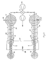
- the device according to FIG. 1 has two regenerators 1, 2 designed as shaft reactors, which are connected to one another at their upper end via a screw tube furnace 3. Approximately in the middle of the screw tube furnace 3 there is a filler neck with a lock 4, through which the solids to be treated are filled.
- a rotatable screw 5 with screw blades 6 is arranged inside the screw tube furnace 3.
- a bed 7, 8 designed as a moving bed, which serves for heat regeneration, discharge devices 9, 10 designed as locks being provided on the bottom of the regenerators 1, 2.
- Burners 16, 17 are arranged laterally in the upper region of the regenerators above the beds 7, 8.
- the solid for example stones or pellets
- the screw blades 6 of the screw 5 are arranged such that they convey the solid in approximately equal amounts from the center to the two ends of the screw 5 and mix at the same time.
- the main burning process takes place with the release of possible harmful gases.
- the largely burned solid falls into the two regenerators 1, 2 and forms the regeneration bed 7, 8.
- cooled solids are discharged from the bottom via the discharge devices 9, 10 .
- the combustion air required for the combustion process is introduced via one of the lines 11, 12 into one of the regenerators 1, 2, which are supplied by the blower is delivered via the four-way valve.
- the air flows, for example, through the moving bed 7 of the regenerator 1, which is indicated by the black arrows, and heats up on the solids of the moving bed 7.
- the air has largely reached the temperature of the escaping gases.
- the air is further heated by the burner 16 to such an extent that the solid can burn in the screw tube furnace 2.
- the combustion gases can only escape through the bed 2 of the regenerator 8, whereby they give off most of their heat to the bed 8.
- the gases emerging at the bottom of the regenerator 2 escape through the four-way valve 13 and the outlet 15 and can be sucked off by an additional blower.
- the four-way valve 13 is changed over and the air now flows through the previously heated bed 8 of the regenerator 2, which is thereby cooled again.
- the burner 17 now takes over the additional heating of the air to the temperature necessary for the fire.
- Fixed cycle times can be set for the mutual switching of the air supply in the respective regenerator 1, 2.
- a control unit can also be provided that switches the four-way valve.
- the temperature of the gas emerging from the bottom of the respective regenerator 1, 2 is measured, the changeover taking place when the temperature of the emerging gases falls below a certain predetermined value.
- the supply of fuel by the burners 16, 17 can be reduced in accordance with the proportion of the combustible components. If the combustible contains more combustible constituents than are required for burning, overheating could result. In this case, cooling is carried out, which is implemented by built-in heat exchangers or by injecting water.
- metal-containing pellets can also be introduced as a solid, which pellets are reduced in the screw tube furnace 3. Then, instead of the air, CO and H2-containing generator gas is introduced into the bottom region of the regenerators 1, 2, which is preheated by the beds 7, 8 of the regenerators. Pre-heated air is then blown in instead of fuel, which leads to partial combustion of the generator gas and provides the heat of reaction.
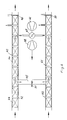
- FIG. 2 shows a further exemplary embodiment of the device for the thermal treatment of solids, in which a moving floor furnace is used.
- the same reference numerals are used for the same parts.
- the solids are also poured via a lock 4 onto the center of a platform 20 on which there is a moving floor 21 with differently directed pushing wedges 22, 23.
- the moving floor 21 By moving the moving floor 21, the solids to be burned are mixed and gradually moved to the two ends 24, 25, of which they fall into the two regenerators 1, 2.
- Distribution troughs 26 are provided for the uniform distribution of the fired solids in the regenerators 1, 2.
- the heat is regenerated in accordance with the exemplary embodiment according to FIG. 1.
- burners 27, 28, 29, 30 or nozzles for supplying air are provided at several different points.
- FIG. 3 shows a further exemplary embodiment in a top view of the device for the thermal treatment of solids, in which two rotary tube furnaces 31, 32 are used.
- the solids to be burned are fed evenly into the two rotary kilns 31, 32 via two feed devices 33, 34.
- the rotary kilns 31, 32 are connected to one another via a hot gas duct 35 and are movably sealed with respect to the hot gas duct 35 and against the regenerators 1, 2 by means of sealing sleeves 36.
- the solids are conveyed to the regenerators 1, 2 by the rotation of the rotary kilns 31, 32.
- the burners 37, 38 are arranged behind the rotary kilns 31, 32 in front of the regenerators 1, 2, but a burner 39 can also be provided in the hot gas duct 35, the burners 37, 38, 39 being actuated alternately.
- the heat regeneration is carried out in accordance with the embodiment of FIG. 1.
- Fig. 4 shows an embodiment with two tunnel kilns 40, 41, which are particularly suitable for firing ceramics.
- the tunnel ovens 40, 41 are connected to feed tunnels 42, 43, the solids to be burned being transported slowly on tunnel wagons 44 via the feed tunnels 42, 43 through tunnel ovens 40, 41.
- Behind the feed tunnels 42, 43, the tunnel ovens 40, 41 are connected to one another via a hot gas duct 45.
- the air supply or the supply of the reducing gases corresponds to the arrangements according to FIGS.
- lock chambers 49, 50 are provided, through which the fired solids and cooled in the tunnel section are discharged.
- the lock chambers 49, 50 are necessary because there is an overpressure or underpressure in front of them. Locks can also be provided in the feed tunnels 42, 43.
- the blower output of the two blowers 46, 48 can, however, be coordinated with one another in such a way that the hot gas duct 45, which connects the two tunnel ovens 40, 41, has approximately the same pressure as in the environment, so that no locks are necessary and through the open feed tunnels 42, 43 no incorrect air can be sucked in or fuel gases can escape. In order to prevent fuel gases from escaping, it is even better to set a low negative pressure in relation to the surroundings, so that a small amount of fresh air is drawn in through the tunnel openings.
- the combustion air supplied via the four-way valve 47 heats up on the fired solids the loaded tunnel car 44, which slowly moves to the locks 49, 50. At the end of the respective tunnel furnace 40, they are further heated by the burner 51 in the hot gas duct 45, so that the solids present on the tunnel carriage 44 can be burned. The combustion gases then cool down on the solids in the other tunnel kiln.
- the heat regeneration thus corresponds to that from the preceding exemplary embodiments, the loaded tunnel wagons being guided through the tunnel furnaces 40, 41 forming the regenerators instead of the bed.
- the tunnel car 44 are loaded so that the solids are evenly flowed through.
Landscapes
- Engineering & Computer Science (AREA)
- Mechanical Engineering (AREA)
- General Engineering & Computer Science (AREA)
- Chemical & Material Sciences (AREA)
- Combustion & Propulsion (AREA)
- Muffle Furnaces And Rotary Kilns (AREA)
- Processing Of Solid Wastes (AREA)
- Waste-Gas Treatment And Other Accessory Devices For Furnaces (AREA)
- Heat Treatments In General, Especially Conveying And Cooling (AREA)
- Treatment Of Sludge (AREA)
- Tunnel Furnaces (AREA)
- Feeding, Discharge, Calcimining, Fusing, And Gas-Generation Devices (AREA)
Abstract
Description
Die Erfindung betrifft ein Verfahren und eine Vorrichtung zur thermischen Behandlung von Feststoffen in oxidierender bzw. reduzierender Umgebung, bei denen der Feststoff in einem Ofen mit heißen oxidierenden bzw. reduzierenden Gasen der thermischen Hauptbehandlung unterzogen werden, nach dem Oberbegriff des Anspruchs 1 und des nebengeordneten Anspruchs 9.The invention relates to a method and a device for the thermal treatment of solids in an oxidizing or reducing environment, in which the solid is subjected to the main thermal treatment in a furnace with hot oxidizing or reducing gases, according to the preamble of
Für das Brennen von Keramiken, Kalk, Zement, schadstoffhaltigen Schlämmen und kontaminierten Gesteinen oder für die Reduktion von Metallhydroxidschlämmen oder Metallhydroxidpellets werden die verschiedensten Ofenbauarten angeboten. Wenn beim Brennvorgang Schadgase entweichen, müssen die Brenngase so geführt werden, daß eine gute Nachverbrennung gewährleistet ist. Um Schadgase möglichst gut zu verbrennen, ist ein hoher Luftüberschuß notwendig. Eine sichere Nachverbrennung der Schadgase, insbesondere bei hohem Luftüberschuß, erfordert somit sehr viel Energie.A wide range of furnace types are available for firing ceramics, lime, cement, polluted sludges and contaminated rocks or for reducing metal hydroxide sludges or metal hydroxide pellets. If harmful gases escape during the burning process, the fuel gases must be guided so that good post-combustion is guaranteed. To harmful gases To burn as well as possible, a large excess of air is necessary. Reliable afterburning of the harmful gases, especially when there is a large excess of air, therefore requires a great deal of energy.
Aus der DE-A-1 154 238 ist ein Verfahren zum Schmelzen von Metallen, Verhütten von Erzen od. dgl. und ein Schachtofen zur Durchführung des Verfahrens offenbart, bei dem eine Schmelzwanne mit zwei Schächten verbunden ist. Das Schmelzgut wird von oben in die Schächte eingegeben und gleichzeitig wird Verbrennungsluft von oben in einen Schacht zugeführt. Im unteren Bereich des Schachtes wird Brennstoff eingedüst, das Schmelzgut wird in der Schmelzwanne geschmolzen und die Abgase treten aus dem anderen Schacht aus, nachdem sie diesen durchströmt haben und ihre Wärme an das Schmelzgut abgegeben haben. In kurzen Intervallen werden die Funktionen der Schächte vertauscht, d.h. die Verbrennungsluft wird von oben in den Schacht, der vorher von unten nach oben mit dem Abgas durchströmt wurde, eingegeben und der andere Schacht wird als Abgasschacht verwendet, wobei dessen Füllung aufgeheizt wird. Die zyklische Umschaltung erfolgt, sobald die Temperatur der aus einem Schacht mit aufzuheizender Füllung oben ausströmenden Abgase einen bestimmten Wert überschreitet.DE-A-1 154 238 discloses a method for melting metals, smelting ores or the like and a shaft furnace for carrying out the method, in which a melting tank is connected to two shafts. The melted material is fed into the shafts from above and at the same time combustion air is fed into a shaft from above. In the lower area of the shaft, fuel is injected, the melting material is melted in the melting tank and the exhaust gases emerge from the other shaft after they have flowed through it and have given up their heat to the melting material. The functions of the shafts are exchanged at short intervals, i.e. the combustion air is introduced from above into the shaft, through which the exhaust gas has previously flowed from bottom to top, and the other shaft is used as the exhaust shaft, the filling of which is heated. The cyclic changeover takes place as soon as the temperature of the exhaust gases flowing out of a shaft with a filling to be heated exceeds a certain value.
Der Erfindung liegt die Aufgabe zugrunde, ein Verfahren und eine Vorrichtung zur thermischen Behandlung von Feststoffen zu schaffen, bei denen die Schadstoffe bei hohem Luftüberschuß und verhältnismäßig niedrigen Brenntemperaturen vollständig verbrannt werden, wobei der Energieverbrauch für die thermische Behandlung minimiert werden soll.The invention has for its object to provide a method and an apparatus for the thermal treatment of solids, in which the pollutants are completely combusted with a high excess of air and relatively low firing temperatures, the energy consumption for the thermal treatment should be minimized.
Diese Aufgabe wird erfindungsgemäß durch die kennzeichnenden Merkmale des Hauptanspruchs und des nebengeordneten Vorrichtungsanspruchs gelöst.This object is achieved according to the invention by the characterizing features of the main claim and the subordinate device claim.
Dadurch, daß die thermisch zu behandelnden Feststoffe direkt in einen Ofen eingegeben werden, und dort einer thermischen Hauptbehandlung unterzogen werden, bevor sie als zwei Teilströme in zwei mit dem Ofen verbundenen Regeneratoren gefördert werden, wobei oxidierende bzw. reduzierende Gase in den einen Regenerator eingeleitet werden und an den der thermischen Hauptbehandlung unterzogenen Feststoffen als Austauschmedium erhitzt werden und wobei die aus dem Ofen austretenden Abgase ihre Wärme an die Feststoffe des anderen Regenerators wieder abgeben, wird eine sehr gute Wärmerückführung gewährleistet, die weiterhin durch die abwechselnde Zuführung von oxidierenden bzw. reduzierenden Gasen in die zwei Regeneratoren verbessert wird und die aus den jeweiligen Regeneratoren austretenden Abgase frei von Schadstoffen sind. Durch die optimale Wärmeregenerierung wird der Energiebedarf stark verringert, und es kann bei sehr hohem Luftüberschuß gearbeitet werden, ohne daß der Energiebedarf zunimmt. Hierdurch ist es möglich, Tone mit hohem organischem Gehalt oder Schlämme mit Schadstoffgehalt zu brennen. Die bei der thermischen Hauptbehandlung im Ofen austretenden Schadgase werden an den großen Kontaktoberflächen verbrannt, so daß das Abgas frei von Schadgasen ist. Weiterhin ist die Verbackungsgefahr der der thermischen Hauptbehandlung unterzogenen Feststoffe relativ gering, da auf der heißesten Zone im jeweiligen Generator keine hohe Schüttung lastet. Durch die mögliche Reduktion von Metalloxiden können metallhaltige Schlämme bei geringem Energieverbrauch recycelt werden.The fact that the solids to be thermally treated are introduced directly into a furnace and subjected to a main thermal treatment there before they are conveyed as two partial streams in two regenerators connected to the furnace, oxidizing or reducing gases being introduced into the one regenerator and on the solids which are subjected to the main thermal treatment as an exchange medium and the exhaust gases emerging from the furnace give off their heat to the solids of the other regenerator, a very good heat recovery is guaranteed, which is furthermore ensured by the alternating supply of oxidizing or reducing gases is improved in the two regenerators and the exhaust gases emerging from the respective regenerators are free of pollutants. The optimal heat regeneration greatly reduces the energy requirement, and it is possible to work with a very high excess of air without the energy requirement increasing. This makes it possible to burn clays with a high organic content or sludges with a pollutant content. The harmful gases escaping in the main thermal treatment are burned on the large contact surfaces, so that the exhaust gas is free of harmful gases. Furthermore, the risk of caking of the solids that are subjected to the main thermal treatment is relatively low, since the hottest zone in the respective generator does not have a high charge. The possible reduction of metal oxides means that metal-containing sludges can be recycled with low energy consumption.
Durch die in den Unteransprüchen angegebenen Maßnahmen sind vorteilhafte Weiterbildungen und Verbesserungen möglich. Ausführungsbeispiele der Erfindung sind in der Zeichnung dargestellt und werden in der nachfolgenden Beschreibung näher erläutert. Es zeigen:
- Fig. 1
- ein erstes Ausführungsbeispiel der erfindungsgemäßen Vorrichtung mit einem Schneckenrohrofen,
- Fig. 2
- ein zweites Ausführungsbeispiel mit einem Schubbodenofen,
- Fig. 3
- ein drittes Ausführungsbeispiel mit Drehrohröfen, und
- Fig. 4
- ein viertes Ausführungsbeispiel mit Doppel-Tunnelöfen.
- Fig. 1
- a first embodiment of the device according to the invention with a screw tube furnace,
- Fig. 2
- a second embodiment with a moving floor oven,
- Fig. 3
- a third embodiment with rotary kilns, and
- Fig. 4
- a fourth embodiment with double tunnel ovens.
Die Vorrichtung nach Fig. 1 weist zwei als Schachtreaktoren ausgebildete Regeneratoren 1, 2 auf, die an ihrem oberen Ende über einen Schneckenrohrofen 3 miteinander verbunden sind. Etwa in der Mitte des Schneckenrohrofens 3 ist ein Einfüllstutzen mit Schleuse 4 angeordnet, über die die zu behandelnden Feststoffe eingefüllt werden.The device according to FIG. 1 has two
Innerhalb des Schneckenrohrofens 3 ist eine drehbare Schnecke 5 mit Schneckenflügeln 6 angeordnet. Innerhalb der Regeneratoren 1, 2 befindet sich jeweils eine als Wanderbett ausgebildete Schüttung 7, 8, die zur Wärmeregenerierung dient, wobei am Boden der Regeneratoren 1, 2 als Schleusen ausgebildete Austragvorrichtungen 9, 10 vorgesehen sind. Weiterhin sind in der Nähe des Bodens der Regeneratoren 1, 2 schematisch angedeutete Gaszufuhr- bzw. -abfuhrleitungen 11, 12, die zu einem Vierwegehahn 13 führen, der mit einem Gebläse 14 verbunden ist und außerdem einen Abgasauslaß 15 aufweist, vorgesehen. Im oberen Bereich der Regeneratoren oberhalb der Schüttungen 7,8 sind seitlich Brenner 16, 17 angeordnet.A
Der Feststoff, beispielsweise Steine oder Pellets, wird über die Schleuse 4 in die Mitte des Schneckenrohrofens 3 eingegeben und in diesem Ofen erhitzt. Die Schneckenflügel 6 der Schnecke 5 sind derart angeordnet, daß sie den Feststoff in etwa gleichen Teilmengen aus der Mitte an die beiden Enden der Schnecke 5 fördern und gleichzeitig durchmischen. Dabei erfolgt der Hauptbrennvorgang mit der Freisetzung möglicher Schadgase. Der weitgehend gebrannte Feststoff fällt in die beiden Regeneratoren 1, 2 und bilden dort die Regenerierschüttung 7, 8. In den Mengen, in denen die gebrannten Feststoffe in die Regeneratoren 1, 2 eintreten, werden abgekühlte Feststoffe am Boden über die Austragvorrichtungen 9, 10 ausgetragen.The solid, for example stones or pellets, is introduced via the
Die für den Brennvorgang benötigte Verbrennungsluft wird über eine der Leitungen 11, 12 in einen der Regeneratoren 1, 2 eingeleitet, die von dem Gebläse über den Vierwegehahn geliefert wird. Die Luft strömt beispielsweise durch das Wanderbett 7 des Regenerators 1, was durch die schwaren Pfeile angedeutet ist,und erwärmt sich an den Feststoffen des Wanderbettes 7. Bei Austritt aus dem Wanderbett 7 hat die Luft weitgehend die Temperatur der austretenden Gase erreicht. Die Luft wird weiter über den Brenner 16 soweit erhitzt, daß im Schneckenrohrofen 2 der Brand des Feststoffes erfolgen kann. Die Verbrennungsgase können nach Austritt aus dem Schneckenrohrofen 3 nur durch die Schüttung 2 des Regenerators 8 entweichen, wobei sie den größten Teil ihrer Wärme an die Schüttung 8 abgeben. Die am Boden des Regenerators 2 austretenden Gase entweichen durch den Vierwegehahn 13 und den Auslaß 15 und können durch ein zusätzliches Gebläse abgesaugt werden. Nach einer gewissen Taktzeit, beispielsweise nach ca. 60 Sekunden, wird der Vierwegehahn 13 umgestellt und die Luft strömt nun durch die vorher erwärmte Schüttung 8 des Regenerators 2, die dadurch wieder gekühlt wird. Der Brenner 17 übernimmt nun die zusätzliche Erhitzung der Luft auf die für den Brand notwendige Temperatur. Für das wechselseitige Umschalten der Luftzufuhr in den jeweiligen Regenerator 1, 2 können feste Taktzeiten eingestellt werden. Es kann aber auch eine Steuereinheit vorgesehen sein, die den Vierwegehahn umschaltet. Dabei wird die Temperatur des aus dem Boden des jeweiligen Regenerators 1, 2 austretenden Gases gemessen, wobei die Umschaltung dann stattfindet, wenn die Temperatur der austretenden Gase unter einem bestimmten vorgegebenen Wert fällt.The combustion air required for the combustion process is introduced via one of the
Wenn im zu brennenden Feststoff brennbare Bestandteile enthalten sind, kann die Zufuhr an Brennstoff durch die Brenner 16, 17 gemäß dem Anteil der brennbaren Bestandteile verringert werden. Falls im Brenngut mehr brennbare Bestandteile enthalten sind als zum Brennen benötigt werden, könnte es zu einer Überhitzung kommen. In diesem Fall wird eine Kühlung vorgenommen, die durch eingebaute Wärmetauscher oder durch Einspritzen von Wasser realisiert wird.If combustible components are contained in the solid to be burned, the supply of fuel by the
In der Vorrichtung nach Fig. 1 kann als Feststoff auch metallhaltige Pellets eingeführt werden, die in dem Schneckenrohrofen 3 reduziert werden. Dann wird anstelle der Luft CO und H₂-haltiges Generatorgas in den Bodenbereich der Regeneratoren 1, 2 eingeführt, das durch die Schüttungen 7,8 der Regeneratoren vorerhitzt wird. Anstelle von Brennstoff wird dann vorerhitzte Luft eingeblasen, die zu einer teilweisen Verbrennung des Generatorgases führt und die Reaktionswärme bereitstellt.In the device according to FIG. 1, metal-containing pellets can also be introduced as a solid, which pellets are reduced in the
In Fig. 2 ist ein weiteres Ausführungsbeispiel der Vorrichtung zur thermischen Behandlung von Feststoffen dargestellt, bei der ein Schubbodenofen verwendet wird. Dabei werden für gleiche Teile gleiche Bezugszeichen verwandt. Die Feststoffe werden ebenfalls über eine Schleuse 4 auf die Mitte einer Plattform 20 geschüttet, auf der sich ein Schubboden 21 mit unterschiedlich gerichteten Schubkeilen 22, 23 befindet. Durch die Bewegung des Schubbodens 21 werden die zu brennenden Feststoffe durchmischt und nach und nach zu den beiden Enden 24, 25 bewegt, von denen sie in die beiden Regeneratoren 1, 2 fallen. Zur gleichmäßigen Verteilung der gebrannten Feststoffe in den Regeneratoren 1, 2 sind Verteilrinnen 26 angebracht. Die Wärmeregenerierung erfolgt entsprechend dem Ausführungsbeispiel nach Fig. 1. Um eine gleichmäßigere Erhitzung der vorerwämten Verbrennungsluft bzw. des vorerwärmten reduzierenden Gases zu erreichen, sind an mehreren unterschiedlichen Stellen Brenner 27, 28, 29, 30 bzw. Düsen zur Zuführung von Luft vorgesehen.2 shows a further exemplary embodiment of the device for the thermal treatment of solids, in which a moving floor furnace is used. The same reference numerals are used for the same parts. The solids are also poured via a
In Fig. 3 ist ein weiteres Ausführungsbeispiel in einer Aufsicht der Vorrichtung zur thermischen Behandlung von Feststoffen gezeigt, bei der zwei Drehrohröfen 31, 32 verwendet werden. Die zu brennenden Feststoffe werden über zwei Zuführvorrichtungen 33, 34 gleichmäßig in die zwei Drehrohröfen 31, 32 eingespeist. Die Drehrohröfen 31, 32 sind über einen Heißgaskanal 35 miteinander verbunden und gegenüber dem Heißgaskanal 35 sowie gegen die Regeneratoren 1, 2 über Dichtungsmanschetten 36 beweglich abgedichtet. Durch die Drehung der Drehrohröfen 31, 32 werden die Feststoffe zu den Regeneratoren 1, 2 befördert. Die Brenner 37, 38 sind hinter den Drehrohröfen 31, 32 vor den Regeneratoren 1, 2 angeordnet, es kann aber auch ein Brenner 39 im Heißgaskanal 35 vorgesehen sein, wobei die Brenner 37, 38, 39 alternierend betätigt werden. Die Wärmeregenerierung wird entsprechend dem Ausführungsbeispiel nach Fig. 1 durchgeführt.3 shows a further exemplary embodiment in a top view of the device for the thermal treatment of solids, in which two
Fig. 4 zeigt ein Ausführungsbeispiel mit zwei Tunnelöfen 40, 41, die insbesondere zum Brennen von Keramiken geeignet sind. Bei der in der Aufsicht dargestellten Vorrichtung sind die Tunnelöfen 40, 41 mit Zuführtunneln 42, 43 verbunden, wobei die zu brennenden Feststoffe auf Tunnelwagen 44 über die Zuführtunnel 42, 43 langsam durch die Tunnelöfen 40, 41 transportiert werden. Hinter den Zuführtunneln 42, 43 sind die Tunnelöfen 40, 41 über einen Heißgaskanal 45 miteinander verbunden. Die Luftzufuhr bzw. die Zufuhr der reduzierenden Gase entspricht den Anordnungen nach den Fig. 1 bis 3, d.h. die Verbrennungsluft bzw. die reduzierenden Gase werden mit einem Gebläse 46 über einen Vierwegehahn 47 wechselseitig in die Tunnelöfen 40, 41 eingeführt und das Abgas wird über ein zweites Gebläse 48 abgesaugt. Am Ende der Tunnelöfen 40, 41 sind Schleusenkammern 49, 50 vorgesehen, über die die gebrannten und in der Tunnelstrecke abgekühlten Feststoffe ausgelassen werden. Die Schleusenkammern 49, 50 sind notwendig, da vor ihnen ein Überdruck bzw. Unterdruck herrscht. In den Zuführtunneln 42, 43 können ebenfalls Schleusen vorgesehen sein. Die Gebläseleistung der beiden Gebläse 46, 48 kann aber so aufeinander abgestimmt sein, daß im Heißgaskanal 45, der die beiden Tunnelöfen 40, 41 verbindet, ungefähr der gleiche Druck wie in der Umgebung herrscht, so daß keine Schleusen notwendig sind und durch die offenen Zuführtunnel 42, 43 keine Fehlluft eingesaugt oder Brenngase entweichen können. Zur Verhinderung des Austritts von Brenngasen ist es sogar besser, einen geringen Unterdruck gegenüber der Umgebung einzustellen, so daß eine kleine Menge Frischluft durch die Tunnelöffnungen eingesaugt wird.Fig. 4 shows an embodiment with two
Die über den Vierwegehahn 47 zugeführte Verbrennungsluft erwärmt sich an den gebrannten Feststoffen auf den beladenen Tunnelwagen 44,die sich langsam zu den Schleusen 49, 50 bewegen. Am Ende des jeweiligen Tunnelofens 40 werden sie durch den Brenner 51 im Heißgaskanal 45 weiter erhitzt, so daß die auf den Tunnelwagen 44 vorhandenen Feststoffe gebrannt werden können. Die Verbrennungsgase kühlen sich dann an den Feststoffen im jeweils anderen Tunnelofen ab. Somit entspricht die Wärmeregenerierung derjenigen aus den vorhergehenden Ausführungsbeispielen, wobei anstelle der Schüttung die beladenen Tunnelwagen durch die die Regeneratoren bildenden Tunnelöfen 40, 41 geführt werden. Die Tunnelwagen 44 sind dabei so beladen, daß die Feststoffe gleichmäßig durchströmt werden.The combustion air supplied via the four-
Claims (18)
- Process for the thermal treatment of solids in an oxidising or reducing environment using regenerators and a kiln in which process the oxidising or reducing gases are fed alternately into the regenerators and are then discharged for a main thermal treatment of the solids and after flowing through kiln and regenerators in the form of exhaust gases, the direction of flow of the admitted oxidising or reducing gases being reversed in a fixed cycle,
characterised in that
the solids are fed into the hot kiln area, undergo main thermal treatment and after main thermal treatment are conveyed in two parts, cooled thermally treated solid being drawn out of the regenerators and that the oxidising or reducing gases fed alternately into the regenerators are heated using the solids having undergone main thermal treatment. - Process according to Claim 1 characterised in that the solids flow continually in a travelling bed through the regenerators.
- Process according to Claim 1 characterised in that the solids flow through the regenerators in several lots.
- Process according to one of Claims 1 to 3 characterised in that the temperature of the gases coming out of the respective regenerator is measured and the alternate supply of combustion air or of the reducing gases is controlled depending on this temperature.
- Process according to one of Claims 1 to 4 characterised in that the solids are pelletised and contain metal oxides, the gas heated in the respective regenerator and in the form of generator gas being re-heated using sub-stoechiometric air flow to a temperature required for reduction.
- Process according to one of Claims 1 to 4 characterised in that the solids are burned with oxidising combustion gases, the supplied combustion air heated in the respective regenerator being re-heated using fuel additive to a temperature necessary for combustion.
- Process according to Claim 5 to 6 characterised in that the air required for reduction or the fuel necessary for combustion is supplied to several various points in order to achieve uniform heating.
- Process according to one of Claims 5 to 7 characterised in that the addition of air of fuel is alternatively controlled in the respective regenerator depending on the supply of combustion air or reducing gases.
- Device for the thermal treament of solids in an oxidising or reducing environment according to Claim 1 with a kiln in which the solids undergo a main thermal treatment and two regenerators, connected to the kiln in which oxidising or reducing gases are supplied alternately to in- or outlets arranged on the ends of the regenerators opposite the kiln, are used for main thermal treatment in the kiln and after flowing through kiln and regenerators are discharged as exhaust gases,
characterised in that
the kiln (3;31,32;40,41) has a supply device (4) for supplying the solids directly into the kiln and a transport device (6,22), which transports the solids that have undergone main thermal treatment in two parts into the regenerators (1,2;40,41) and that each regenerator (1,2;40,41) is connected with its end opposite the kiln to a discharge device (9,10) for the thermally treated solid. - Device according to Claim 9 characterised in that a four-way valve (13,45) is provided through which the oxidising or reducing gases can be supplied and the exhaust gases coming from the regenerators (1,2;40,41) can be discharged.
- Device according to Claim 9 or 10 characterised in that the supply device (4) for the solids is arranged in the middle of the kiln connecting the regenerators and that the regenerators (1,2) are designed as shaft reactors, the discharge device (9,10) for the solids forming a travelling bed and having undergone thermal main treatment is arranged at the base of each shaft reactor.
- Device according to Claim 11 characterised in that the kiln connecting the regenerators (1,2) is designed as a spiral tube reactor (3), the spiral blades forming the transport device.
- Device according to Claim 11 characterised in that the kiln connecting the regenerators (1,2) is designed as a sliding floor reactor (21), propelled sliding blocks transporting the solids to the regenerators.
- Device according to Claim 13 characterised in that distribution troughs (26) are provided beneath the sliding floor reactor (21) to evenly distribute the solids in the regenerators (1,2).
- Device according to one of the claims 9 to 11 characterised in that the kiln connecting the regenerators (1,2) consists of a double rotating tubular kiln (31,32) with a connecting channel (35) between the double rotating tubular kiln (31,32), each double rotating tubular kiln (31,32) having a supply device (33,34) and that during main thermal treatment the solids can be transported via transport devices in the double rotating tubular kilns in approximately equal quantities to the two regenerators.
- Device according to Claim 8 or 9 characterised in that the regenerators are designed as parallel tunnel kilns (40,41) and the kiln connecting the regenerators (40,41) consists of part-areas of the tunnel kilns (40,41) between which a connecting channel (45) is provided.
- Device according to Claim 16 characterised in that exhaust fans (46,48) are provided for the supply of the combustion air and the removal of the exhaust gases, the duty of which exhaust fans is matched to the other so that approximately the same pressure as in the environment prevails in the connecting channel (45).
- Device according to Claim 17 characterised in that the exhaust duties of the two exhaust fans (46,48) are matched such that a low negative pressure is provided in the connecting channel (45) compared with the environment.
Priority Applications (1)
| Application Number | Priority Date | Filing Date | Title |
|---|---|---|---|
| AT89730110T ATE92613T1 (en) | 1988-05-09 | 1989-04-27 | METHOD AND DEVICE FOR THERMAL TREATMENT OF SOLIDS. |
Applications Claiming Priority (2)
| Application Number | Priority Date | Filing Date | Title |
|---|---|---|---|
| DE3816492A DE3816492A1 (en) | 1988-05-09 | 1988-05-09 | METHOD AND DEVICE FOR THE THERMAL TREATMENT OF SOLIDS |
| DE3816492 | 1988-05-09 |
Publications (3)
| Publication Number | Publication Date |
|---|---|
| EP0342148A2 EP0342148A2 (en) | 1989-11-15 |
| EP0342148A3 EP0342148A3 (en) | 1990-03-28 |
| EP0342148B1 true EP0342148B1 (en) | 1993-08-04 |
Family
ID=6354374
Family Applications (1)
| Application Number | Title | Priority Date | Filing Date |
|---|---|---|---|
| EP89730110A Expired - Lifetime EP0342148B1 (en) | 1988-05-09 | 1989-04-27 | Process and installation for the thermal treatment of solids |
Country Status (4)
| Country | Link |
|---|---|
| EP (1) | EP0342148B1 (en) |
| AT (1) | ATE92613T1 (en) |
| DE (2) | DE3816492A1 (en) |
| ES (1) | ES2043086T3 (en) |
Families Citing this family (2)
| Publication number | Priority date | Publication date | Assignee | Title |
|---|---|---|---|---|
| DE4224778A1 (en) * | 1992-07-27 | 1994-02-03 | Horst Dr Grochowski | Disposal procedures for environmental toxins |
| CN111288438B (en) * | 2020-03-26 | 2021-09-24 | 江苏大学 | Fluidized bed combustion furnace and combustion method |
Family Cites Families (7)
| Publication number | Priority date | Publication date | Assignee | Title |
|---|---|---|---|---|
| DE59234C (en) * | 1889-10-29 | 1891-10-12 | AKTIEN-GESELLSCHAFT FÜR GLASINDUSTRIE VORM. FRIEDR. SIEMENS in Dresden | Continuously working twin shaft furnace with regenerative firing with solid or liquid fuel and FRIEDRICH SlEMENSscher free flame development |
| DE320439C (en) * | 1913-12-10 | 1920-04-22 | Antony Gauchet | Process and double furnace for utilizing the exhaust gas heat in cupolas |
| DE601795C (en) * | 1931-02-05 | 1934-08-24 | Mathias Fraenkl | Two-shaft smelting and reduction furnace and process for its operations |
| US2544091A (en) * | 1948-05-10 | 1951-03-06 | Jordan Res Lab Inc | Method of melting |
| US2959629A (en) * | 1956-11-19 | 1960-11-08 | Pure Oil Co | Fixed bed, pyrolytic, hydrocarbon conversion process employing a granular, heat-transfer medium |
| DE1154238B (en) * | 1958-10-02 | 1963-09-12 | Alois Schmidt | Process for melting metals, refining ores or the like, and shaft furnace for carrying out this process |
| SE395714B (en) * | 1974-02-20 | 1977-08-22 | Skf Ind Trading & Dev | METHODS AND DEVICES FOR MANUFACTURE OF METALS FROM OXIDIC MATERIAL |
-
1988
- 1988-05-09 DE DE3816492A patent/DE3816492A1/en not_active Withdrawn
-
1989
- 1989-04-27 EP EP89730110A patent/EP0342148B1/en not_active Expired - Lifetime
- 1989-04-27 ES ES89730110T patent/ES2043086T3/en not_active Expired - Lifetime
- 1989-04-27 DE DE8989730110T patent/DE58905101D1/en not_active Expired - Fee Related
- 1989-04-27 AT AT89730110T patent/ATE92613T1/en not_active IP Right Cessation
Also Published As
| Publication number | Publication date |
|---|---|
| ES2043086T3 (en) | 1993-12-16 |
| EP0342148A3 (en) | 1990-03-28 |
| DE3816492A1 (en) | 1989-11-16 |
| EP0342148A2 (en) | 1989-11-15 |
| DE58905101D1 (en) | 1993-09-09 |
| ATE92613T1 (en) | 1993-08-15 |
Similar Documents
| Publication | Publication Date | Title |
|---|---|---|
| DE3788871T2 (en) | PROCESS FOR WASTE PROCESSING AND ROTATORS FOR THIS PURPOSE. | |
| EP0306695B1 (en) | Hot gas generating device using thermal afterburning | |
| DE69228607T2 (en) | Process and apparatus for continuous preheating of scrap | |
| EP1334954B1 (en) | Installation for manufacturing cement clinker | |
| DE2636374C2 (en) | Method and device for cleaning exhaust gas | |
| DE2325468A1 (en) | DEVICE FOR SINTERING CEMENT AND SIMILAR MATERIALS | |
| EP1146304A1 (en) | Double chamber furnace for immersion smelting of contaminated aluminium scrap | |
| DE2614952C2 (en) | Method and device for the continuous burning of carbon blanks | |
| DE3444073A1 (en) | METHOD AND PLANT FOR COMBUSTION OF WASTE LIKE HOME, INDUSTRIAL AND SPECIAL WASTE | |
| EP0854339A1 (en) | Process and installation for the heat treatment of fine-grained charges | |
| DE2349932A1 (en) | METHOD AND DEVICE FOR HEAT TREATMENT OF MATERIAL | |
| EP0716052A1 (en) | Process and installation for cooling and fabrication of bulk material | |
| EP0174676B1 (en) | Thermal treatment process of grains or agglomerates on a travelling grate | |
| DE19818953C1 (en) | Method and control apparatus for melting glass | |
| CH638296A5 (en) | METHOD AND SYSTEM FOR BURNING CARBONOUS RAW MATERIALS BY MEANS OF SOLID FUELS IN A DC-REGENERATIVE CHAMBER. | |
| DE2810043C2 (en) | ||
| DE1927558B1 (en) | Process and device for the production of sponge iron from oxidic iron ores | |
| EP0342148B1 (en) | Process and installation for the thermal treatment of solids | |
| DE2657239A1 (en) | Roasting lime in double shaft furnace - where shafts are used alternately for regenerating heating of air used to burn fuel | |
| EP0039798A1 (en) | Method of firing and sintering waste washings | |
| DE1433339A1 (en) | Process for hard burning pellets | |
| EP0704658B1 (en) | Process for thermal treatment of waste material, especially refuse | |
| DE10051648A1 (en) | Process and shaft melting gasifier for thermal treatment and recycling of waste materials | |
| DE4023432A1 (en) | Tunnel kiln - with heat exchangers for preheating gas circuit fed by hot gases from cooling zone | |
| DE3537595A1 (en) | Method and installation for utilising moist waste, in particular sewage sludge |
Legal Events
| Date | Code | Title | Description |
|---|---|---|---|
| PUAI | Public reference made under article 153(3) epc to a published international application that has entered the european phase |
Free format text: ORIGINAL CODE: 0009012 |
|
| AK | Designated contracting states |
Kind code of ref document: A2 Designated state(s): AT BE CH DE ES FR GB GR IT LI LU NL SE |
|
| PUAL | Search report despatched |
Free format text: ORIGINAL CODE: 0009013 |
|
| AK | Designated contracting states |
Kind code of ref document: A3 Designated state(s): AT BE CH DE ES FR GB GR IT LI LU NL SE |
|
| 17P | Request for examination filed |
Effective date: 19900817 |
|
| 17Q | First examination report despatched |
Effective date: 19920124 |
|
| ITF | It: translation for a ep patent filed | ||
| GRAA | (expected) grant |
Free format text: ORIGINAL CODE: 0009210 |
|
| AK | Designated contracting states |
Kind code of ref document: B1 Designated state(s): AT BE CH DE ES FR GB GR IT LI LU NL SE |
|
| PG25 | Lapsed in a contracting state [announced via postgrant information from national office to epo] |
Ref country code: GR Free format text: LAPSE BECAUSE OF FAILURE TO SUBMIT A TRANSLATION OF THE DESCRIPTION OR TO PAY THE FEE WITHIN THE PRESCRIBED TIME-LIMIT Effective date: 19930804 |
|
| REF | Corresponds to: |
Ref document number: 92613 Country of ref document: AT Date of ref document: 19930815 Kind code of ref document: T |
|
| REF | Corresponds to: |
Ref document number: 58905101 Country of ref document: DE Date of ref document: 19930909 |
|
| GBT | Gb: translation of ep patent filed (gb section 77(6)(a)/1977) |
Effective date: 19930913 |
|
| ET | Fr: translation filed | ||
| REG | Reference to a national code |
Ref country code: ES Ref legal event code: FG2A Ref document number: 2043086 Country of ref document: ES Kind code of ref document: T3 |
|
| PGFP | Annual fee paid to national office [announced via postgrant information from national office to epo] |
Ref country code: NL Payment date: 19940430 Year of fee payment: 6 |
|
| PGFP | Annual fee paid to national office [announced via postgrant information from national office to epo] |
Ref country code: GB Payment date: 19940520 Year of fee payment: 6 Ref country code: FR Payment date: 19940520 Year of fee payment: 6 |
|
| PGFP | Annual fee paid to national office [announced via postgrant information from national office to epo] |
Ref country code: DE Payment date: 19940524 Year of fee payment: 6 |
|
| PGFP | Annual fee paid to national office [announced via postgrant information from national office to epo] |
Ref country code: AT Payment date: 19940525 Year of fee payment: 6 |
|
| PGFP | Annual fee paid to national office [announced via postgrant information from national office to epo] |
Ref country code: SE Payment date: 19940530 Year of fee payment: 6 |
|
| PGFP | Annual fee paid to national office [announced via postgrant information from national office to epo] |
Ref country code: LU Payment date: 19940531 Year of fee payment: 6 Ref country code: ES Payment date: 19940531 Year of fee payment: 6 Ref country code: BE Payment date: 19940531 Year of fee payment: 6 |
|
| PLBE | No opposition filed within time limit |
Free format text: ORIGINAL CODE: 0009261 |
|
| STAA | Information on the status of an ep patent application or granted ep patent |
Free format text: STATUS: NO OPPOSITION FILED WITHIN TIME LIMIT |
|
| PGFP | Annual fee paid to national office [announced via postgrant information from national office to epo] |
Ref country code: CH Payment date: 19940624 Year of fee payment: 6 |
|
| 26N | No opposition filed | ||
| EPTA | Lu: last paid annual fee | ||
| EAL | Se: european patent in force in sweden |
Ref document number: 89730110.7 |
|
| PG25 | Lapsed in a contracting state [announced via postgrant information from national office to epo] |
Ref country code: LU Free format text: LAPSE BECAUSE OF NON-PAYMENT OF DUE FEES Effective date: 19950427 Ref country code: GB Effective date: 19950427 Ref country code: AT Effective date: 19950427 |
|
| PG25 | Lapsed in a contracting state [announced via postgrant information from national office to epo] |
Ref country code: SE Effective date: 19950428 Ref country code: ES Free format text: LAPSE BECAUSE OF NON-PAYMENT OF DUE FEES Effective date: 19950428 |
|
| PG25 | Lapsed in a contracting state [announced via postgrant information from national office to epo] |
Ref country code: LI Effective date: 19950430 Ref country code: CH Effective date: 19950430 Ref country code: BE Effective date: 19950430 |
|
| BERE | Be: lapsed |
Owner name: MICHEL-KIM HERWIG Effective date: 19950430 |
|
| PG25 | Lapsed in a contracting state [announced via postgrant information from national office to epo] |
Ref country code: NL Effective date: 19951101 |
|
| REG | Reference to a national code |
Ref country code: CH Ref legal event code: PL |
|
| PG25 | Lapsed in a contracting state [announced via postgrant information from national office to epo] |
Ref country code: FR Effective date: 19951229 |
|
| NLV4 | Nl: lapsed or anulled due to non-payment of the annual fee |
Effective date: 19951101 |
|
| GBPC | Gb: european patent ceased through non-payment of renewal fee |
Effective date: 19950427 |
|
| PG25 | Lapsed in a contracting state [announced via postgrant information from national office to epo] |
Ref country code: DE Effective date: 19960103 |
|
| EUG | Se: european patent has lapsed |
Ref document number: 89730110.7 |
|
| REG | Reference to a national code |
Ref country code: FR Ref legal event code: ST |
|
| REG | Reference to a national code |
Ref country code: ES Ref legal event code: FD2A Effective date: 19990503 |
|
| PG25 | Lapsed in a contracting state [announced via postgrant information from national office to epo] |
Ref country code: IT Free format text: LAPSE BECAUSE OF NON-PAYMENT OF DUE FEES;WARNING: LAPSES OF ITALIAN PATENTS WITH EFFECTIVE DATE BEFORE 2007 MAY HAVE OCCURRED AT ANY TIME BEFORE 2007. THE CORRECT EFFECTIVE DATE MAY BE DIFFERENT FROM THE ONE RECORDED. Effective date: 20050427 |