EP0341967A2 - Dispensing apparatus for nasal administration of an aerosol product - Google Patents
Dispensing apparatus for nasal administration of an aerosol product Download PDFInfo
- Publication number
- EP0341967A2 EP0341967A2 EP89304660A EP89304660A EP0341967A2 EP 0341967 A2 EP0341967 A2 EP 0341967A2 EP 89304660 A EP89304660 A EP 89304660A EP 89304660 A EP89304660 A EP 89304660A EP 0341967 A2 EP0341967 A2 EP 0341967A2
- Authority
- EP
- European Patent Office
- Prior art keywords
- housing
- container
- outlet duct
- chamber
- dispensing
- Prior art date
- Legal status (The legal status is an assumption and is not a legal conclusion. Google has not performed a legal analysis and makes no representation as to the accuracy of the status listed.)
- Withdrawn
Links
- 239000000443 aerosol Substances 0.000 title claims abstract description 10
- 239000000463 material Substances 0.000 claims description 8
- 239000012528 membrane Substances 0.000 claims description 3
- 238000006073 displacement reaction Methods 0.000 claims description 2
- 238000007789 sealing Methods 0.000 claims description 2
- 239000007921 spray Substances 0.000 claims description 2
- 238000003780 insertion Methods 0.000 abstract description 3
- 230000037431 insertion Effects 0.000 abstract description 3
- 230000015572 biosynthetic process Effects 0.000 description 7
- 238000005755 formation reaction Methods 0.000 description 7
- 238000010276 construction Methods 0.000 description 4
- 229920003023 plastic Polymers 0.000 description 4
- 238000011109 contamination Methods 0.000 description 3
- 239000000428 dust Substances 0.000 description 3
- 239000004033 plastic Substances 0.000 description 3
- 229920002457 flexible plastic Polymers 0.000 description 2
- 239000003595 mist Substances 0.000 description 2
- QRDJCCQTEQVLKC-REJBHVJUSA-N C[C@@H]1[C@@H](C2)C2CC1 Chemical compound C[C@@H]1[C@@H](C2)C2CC1 QRDJCCQTEQVLKC-REJBHVJUSA-N 0.000 description 1
- 239000004743 Polypropylene Substances 0.000 description 1
- 230000000994 depressogenic effect Effects 0.000 description 1
- 239000013536 elastomeric material Substances 0.000 description 1
- 229940126601 medicinal product Drugs 0.000 description 1
- -1 polypropylene Polymers 0.000 description 1
- 229920001155 polypropylene Polymers 0.000 description 1
- 230000000717 retained effect Effects 0.000 description 1
- 229920003051 synthetic elastomer Polymers 0.000 description 1
- 239000005061 synthetic rubber Substances 0.000 description 1
Images

Classifications
-
- A—HUMAN NECESSITIES
- A61—MEDICAL OR VETERINARY SCIENCE; HYGIENE
- A61M—DEVICES FOR INTRODUCING MEDIA INTO, OR ONTO, THE BODY; DEVICES FOR TRANSDUCING BODY MEDIA OR FOR TAKING MEDIA FROM THE BODY; DEVICES FOR PRODUCING OR ENDING SLEEP OR STUPOR
- A61M15/00—Inhalators
- A61M15/009—Inhalators using medicine packages with incorporated spraying means, e.g. aerosol cans
Definitions
- This invention relates to dispensing apparatus for use with a pressurised dispensing container and in particular but not exclusively to dispensing apparatus for nasally administering medicinal products in aerosol form.
- dispensing apparatus comprising a housing defining a chamber for a pressurised dispensing container and an outlet duct through which a product may be dispensed in aerosol form.
- the housing generally provides for axial movement of a cylindrical container such that a valve of the container is actuated in response to relative movement between the container and the housing.
- outlet duct is susceptible to contamination by the ingress of foreign matter when the apparatus is not in use and the external surfaces of the outlet duct may become soiled.
- housing must include an access aperture through which access may be gained to the pressurised dispensing container in order to insert a fresh container or remove the container to permit cleansing of the housing, this aperture also providing a point of entry for contamination to the chamber.
- a dispensing apparatus for a pressurised dispensing container containing a product to be dispensed, the apparatus comprising a housing defining a chamber within which the container is slidably received in use, an outlet duct communicating with the chamber for the discharge of dispensed product in aerosol form, a cover hingedly connected to the housing and movable between a closed position in which the outlet duct is enclosed and an open position in which the outlet duct is exposed for use, the housing comprising a valve actuator connected to a nozzle adjacent the outlet duct and cooperating with a dispensing valve of the container in use to dispense an aerosol spray through the outlet duct, the valve being actuated by displacement of the container towards the valve actuator, the housing defining an access aperture through which the container may be inserted or removed, wherein the housing includes an openable closure normally sealing the access aperture and the housing further comprises a bellows portion defining an end wall of the chamber which is movable relative to the actuator to provide an actuating stroke of the
- An advantage of such an arrangement is that the access aperture is only opened during insertion or removal of a container so that the chanber is normally sealed apart from the presence of the outlet duct so that the ingress of foreign matter is minimised. Furthermore the external surfaces of the outlet duct are enclosed when the apparatus is not in use thereby preventing soiling.
- the closure may comprise a side portion hingedly connected to a main body of the housing and may conveniently be hingedly connected by means of a membrane hinge.
- the closure may be an end cap including the bellows portion and may be formed of a plastics material of greater flexibility than that of the main body.
- the end cap may conveniently be a snap fit with the main body of the housing.
- the first embodiment of the invention as shown in Figures 1 to 6 comprises a dispensing apparatus 1 containing a cylindrical pressurised dispensing container 2.
- the apparatus 1 has a housing 3 of polypropylene defining a cylindrical chamber 4 within which the container is located.
- An outlet duct 5 projects from the housing 3 and communicates between a lower end 21 of the chamber 4 and an outlet 6.
- the container 2 has a dispensing valve 20 having valve actuating stem 8 which is received in a valve actuator 9 which forms part of the housing 3 and is located at the lower end 21 of the chamber 4.
- the valve actuator 9 is arranged such that product dispensed through the stem 8 is directed by the actuator through a nozzle 22 in a direction such that an aerosol mist is discharged through the duct 5 and emerges from the outlet 6.
- the valve actuating stem 8 extends axially from the lower end 23 of the container 2 and the upper end 24 of the container rests in contact with an end wall 25 of the housing 3.
- the housing 3 includes a bellows portion 10 adjacent the end wall 25 arranged such that by flexure of the bellows portion the end wall 25 is movable towards and away from the actuator 9.
- the housing 3 has a side portion 11 which is hingedly connected by means of a membrane hinge 12 to the main body 13 of the housing, the side portion thereby forming an openable closure to provide an access aperture 26 for loading the container 2 into the chamber 4.
- the side portion 11 is normally retained in a closed position by snap fit connectors (not shown) operable between the side portion and the main body 13.
- a cover 14 comprises a part annular profile of generally U-shaped cross-section and comprising side walls 15 and 16 connected by a part cylindrical connecting wall 17.
- the side walls 15 and 16 each include hinge formations 19 cooperable with hinge formations 18 on the outer walls of the housing 3, the arrangement being such that the cover 14 is movable between an open position as shown in Figure 1 in which the cover is disposed on the opposite side of the housing 3 from the duct 5 and a closed position as shown in Figure 3 in which the cover encloses the duct 5.
- the apparatus 1 In use the apparatus 1 is normally stored in the closed condition as shown in Figures 3 and 4 in which the cover 14 shields the outlet duct 5 against the ingress of foreign matter such as dust and prevents soiling of the external surfaces of the duct.
- the cover 14 When it is required to use the apparatus 1 for dispensing the product the cover 14 is moved into its open position as shown in Figures 1 and 2 thereby revealing the outlet duct 5. In this position the cover 14 also does not obstruct access to the bellows portion 10 so that the user holds the housing 3 in one hand with an index finger placed upon the end wall 25.
- the outlet duct 5 is then nasally inserted and the end wall 25 depressed to move the container 2 towards the actuator 9 with respect to which the stem 8 remains fixed.
- valve 20 is then actuated and a quantity of the product is dispensed through the outlet 6 via the nozzle 22. Manual pressure is then released and the container 2 returns to its rest position by virtue of spring action provided by the valve 20 biassing the stem into an extended position.
- the container 2 is accessible by means of the openable closure 11 when for example it is necessary to remove the container 2 from the housing 3 to wash the housing after a period of use or when it is required to fit a fresh container. Prior to opening the closure 11 it is necessary to detach the cover 14, this being accommodated by flexure of the side walls 15 and 16. In the closed position of the side portion 11 the chamber 4 is sealed except for the outlet 6.
- the apparatus 1 may also be provided with snap fit formations (not shown) for retaining the cover 14 in its open and closed positons respectively.
- FIG. 7 to 12 A second embodiment of the invention is shown in Figures 7 to 12 in which corresponding reference numerals have been used where appropriate to those appearing in Figures 1 to 6.
- Dispensing apparatus 30 as shown in Figures 7 to 12 comprises a modified housing 33 having an outlet duct 5 providing communication between a chamber 4 and an outlet 6.
- a pressurised dispensing container 2 received within the chamber 4 is arranged such that a valve actuating stem 8 is cooperable with an actuator 9 of the dispensing apparatus 30, the container 2 being axially slidably received within the housing 33 such that upon depression of the container an aerosol mist of product is dispensed through the duct 5 from the outlet 6.
- the housing 33 is provided with a cover 34 in the form of an oblate hemi-spheroidal shell in which hinge formations 36 are formed at the opposite flattened poles thereof.
- the housing 33 is provided with cooperating hinge formations 37, the arrangement being such that the cover 34 is pivotal between an open position as shown in Figures 7 and 8 in which the outlet duct 5 is uncovered and a closed position as shown in Figures 9 and 10 in which both the duct 5 is enclosed.
- the housing is of two part construction having a main body 38 formed of a rigid plastics material and an end cap 39 formed of a more flexible plastics material.
- the cap 39 incorporates a bellows portion 10 adjacent an end wall 25 which is movable by bellows action towards and away from the actuator 9.
- the cap 39 is shown in its normal position in which it forms a seal to the upper end 23 of the chamber 4.
- the cap 39 is connected to the main body 38 by means of a snap fit connector 40 which is arranged to provide an airtight seal.
- the cap 39 is separable from the main body 38 to provide an access aperture 41 through which the container may be inserted or removed as required.
- the cover 34 By suitably positioning the cover 34 relative to the housing 33 it is not necessary to disconnect the cover 34 from the housing prior to removal of the cap 39.
- the dispensing operation of the apparatus 30 in use is similar to that described above with reference to dispensing apparatus 1 in that flexure of the bellows portion 10 permits manual depression of the container 2 by finger pressure applied externally to the end wall 25 of the housing 33.
- the cover 34 fits snugly to the housing 33 in the closed position so that the apparatus 30 is effectively sealed against the ingress of foreign matter such as dust.
- Snap fit formations may also be provided for retaining the cover 24 in its open and closed positions respectively.
- the construction of the bellows portion 10 may alternatively be such that the container 2 is lightly biassed by resilience of the bellows portion into seating contact with the actuator 9. This bias must however be arranged to be insufficient to actuate the valve 20.
- the housing and cover are in each case preferably moulded from plastics materials and the cover may be formed from transparent or semi-transparent plastics material.
- the outlet duct 5 may alternatively be of a suitable shape for oral insertion.
- the cap may be formed of the same material as the main body of the housing provided suitable thinning in the region of the bellows portion ensures sufficient flexibility to allow bellows action.
- the cap may alternatively be formed of a more flexible plastics material or an elastomeric material such as synthetic rubber.
Landscapes
- Health & Medical Sciences (AREA)
- Engineering & Computer Science (AREA)
- Bioinformatics & Cheminformatics (AREA)
- Pulmonology (AREA)
- Anesthesiology (AREA)
- Biomedical Technology (AREA)
- Heart & Thoracic Surgery (AREA)
- Hematology (AREA)
- Life Sciences & Earth Sciences (AREA)
- Animal Behavior & Ethology (AREA)
- General Health & Medical Sciences (AREA)
- Public Health (AREA)
- Veterinary Medicine (AREA)
- Containers And Packaging Bodies Having A Special Means To Remove Contents (AREA)
Abstract
Description
- This invention relates to dispensing apparatus for use with a pressurised dispensing container and in particular but not exclusively to dispensing apparatus for nasally administering medicinal products in aerosol form.
- It is known to provide dispensing apparatus comprising a housing defining a chamber for a pressurised dispensing container and an outlet duct through which a product may be dispensed in aerosol form. The housing generally provides for axial movement of a cylindrical container such that a valve of the container is actuated in response to relative movement between the container and the housing.
- A problem associated with such apparatus is that the outlet duct is susceptible to contamination by the ingress of foreign matter when the apparatus is not in use and the external surfaces of the outlet duct may become soiled. A further problem is that the housing must include an access aperture through which access may be gained to the pressurised dispensing container in order to insert a fresh container or remove the container to permit cleansing of the housing, this aperture also providing a point of entry for contamination to the chamber.
- It is known from EP-0075548 to provide a cover which is pivotally connected to the housing and movable such that in a closed position the cover encloses both the access aperture and the outlet duct and in an open position both the aperture and outlet duct are exposed. In the open position the container is accessible through the access aperture so that a user can manually depress the container such that a dispensing valve of the container is actuated by engagement with a valve actuator having a nozzle formed in the housing adjacent to the outlet duct.
- It has been found that even with such a cover contamination of the chamber with foreign matter such as dust continues to be a problem because the access aperture opens whenever the outlet duct is uncovered for use.
- It has also been proposed in US-3429310 to provide an access aperture which is normally closed by a closure in the form of a cap which is slidably mounted on the main body of the housing so that movement of the cap causes actuating movement of the container. In this arrangement however although the outlet of the outlet duct is covered between use by a flap the external surfaces of the outlet duct are always exposed and liable to become soiled.
- According to the present invention a dispensing apparatus for a pressurised dispensing container containing a product to be dispensed, the apparatus comprising a housing defining a chamber within which the container is slidably received in use, an outlet duct communicating with the chamber for the discharge of dispensed product in aerosol form, a cover hingedly connected to the housing and movable between a closed position in which the outlet duct is enclosed and an open position in which the outlet duct is exposed for use, the housing comprising a valve actuator connected to a nozzle adjacent the outlet duct and cooperating with a dispensing valve of the container in use to dispense an aerosol spray through the outlet duct, the valve being actuated by displacement of the container towards the valve actuator, the housing defining an access aperture through which the container may be inserted or removed, wherein the housing includes an openable closure normally sealing the access aperture and the housing further comprises a bellows portion defining an end wall of the chamber which is movable relative to the actuator to provide an actuating stroke of the container.
- An advantage of such an arrangement is that the access aperture is only opened during insertion or removal of a container so that the chanber is normally sealed apart from the presence of the outlet duct so that the ingress of foreign matter is minimised. Furthermore the external surfaces of the outlet duct are enclosed when the apparatus is not in use thereby preventing soiling.
- The closure may comprise a side portion hingedly connected to a main body of the housing and may conveniently be hingedly connected by means of a membrane hinge.
- Alternatively the closure may be an end cap including the bellows portion and may be formed of a plastics material of greater flexibility than that of the main body. The end cap may conveniently be a snap fit with the main body of the housing.
- Embodiments of the present invention will now be described by way of example only and with reference to the accompanying drawings of which:
- Figure 1 is a side elevation of a first embodiment showing a dispensing apparatus with the cover in the open position;
- Figure 2 is a plan view of the apparatus of Figure 1 with the cover in the open position;
- Figure 3 is a side elevation of the apparatus in Figures 1 and 2 with the cover shown in the closed position;
- Figure 4 is a plan view of the apparatus of Figure 3 with the cover in the closed position;
- Figure 5 is a partly sectioned exploded view of the apparatus of Figures 1 to 4;
- Figure 6 is an exploded plan view of the apparatus of Figures 1 to 5 showing the access aperture in an open condition;
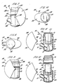
- Figure 7 is a side elevation of a second embodiment showing a dispensing apparatus with the cover in the open position;
- Figure 8 is a plan view of the apparatus of Figure 7 with the cover in the open position;
- Figure 9 is a side elevation of the apparatus of Figures 7 and 8 with the cover in the closed position;
- Figure 10 is a plan view of the apparatus of Figures 7 to 9 with the cover in the closed position;
- Figure 11 is a sectional elevation of the apparatus of Figures 7 to 10; and
- Figure 12 is an exploded elevation of the apparatus of Figures 7 to 11 showing the access aperture in an open condition.
- The first embodiment of the invention as shown in Figures 1 to 6 comprises a dispensing apparatus 1 containing a cylindrical
pressurised dispensing container 2. The apparatus 1 has ahousing 3 of polypropylene defining a cylindrical chamber 4 within which the container is located. Anoutlet duct 5 projects from thehousing 3 and communicates between alower end 21 of the chamber 4 and anoutlet 6. Thecontainer 2 has a dispensingvalve 20 having valve actuatingstem 8 which is received in a valve actuator 9 which forms part of thehousing 3 and is located at thelower end 21 of the chamber 4. The valve actuator 9 is arranged such that product dispensed through thestem 8 is directed by the actuator through a nozzle 22 in a direction such that an aerosol mist is discharged through theduct 5 and emerges from theoutlet 6. - The valve actuating
stem 8 extends axially from thelower end 23 of thecontainer 2 and theupper end 24 of the container rests in contact with anend wall 25 of thehousing 3. Thehousing 3 includes abellows portion 10 adjacent theend wall 25 arranged such that by flexure of the bellows portion theend wall 25 is movable towards and away from the actuator 9. - The
housing 3 has a side portion 11 which is hingedly connected by means of amembrane hinge 12 to themain body 13 of the housing, the side portion thereby forming an openable closure to provide anaccess aperture 26 for loading thecontainer 2 into the chamber 4. The side portion 11 is normally retained in a closed position by snap fit connectors (not shown) operable between the side portion and themain body 13. - A
cover 14 comprises a part annular profile of generally U-shaped cross-section and comprisingside walls side walls hinge formations 19 cooperable withhinge formations 18 on the outer walls of thehousing 3, the arrangement being such that thecover 14 is movable between an open position as shown in Figure 1 in which the cover is disposed on the opposite side of thehousing 3 from theduct 5 and a closed position as shown in Figure 3 in which the cover encloses theduct 5. - In use the apparatus 1 is normally stored in the closed condition as shown in Figures 3 and 4 in which the
cover 14 shields theoutlet duct 5 against the ingress of foreign matter such as dust and prevents soiling of the external surfaces of the duct. When it is required to use the apparatus 1 for dispensing the product thecover 14 is moved into its open position as shown in Figures 1 and 2 thereby revealing theoutlet duct 5. In this position thecover 14 also does not obstruct access to thebellows portion 10 so that the user holds thehousing 3 in one hand with an index finger placed upon theend wall 25. Theoutlet duct 5 is then nasally inserted and theend wall 25 depressed to move thecontainer 2 towards the actuator 9 with respect to which thestem 8 remains fixed. Thevalve 20 is then actuated and a quantity of the product is dispensed through theoutlet 6 via the nozzle 22. Manual pressure is then released and thecontainer 2 returns to its rest position by virtue of spring action provided by thevalve 20 biassing the stem into an extended position. - The
container 2 is accessible by means of the openable closure 11 when for example it is necessary to remove thecontainer 2 from thehousing 3 to wash the housing after a period of use or when it is required to fit a fresh container. Prior to opening the closure 11 it is necessary to detach thecover 14, this being accommodated by flexure of theside walls outlet 6. - The apparatus 1 may also be provided with snap fit formations (not shown) for retaining the
cover 14 in its open and closed positons respectively. - A second embodiment of the invention is shown in Figures 7 to 12 in which corresponding reference numerals have been used where appropriate to those appearing in Figures 1 to 6.
- Dispensing
apparatus 30 as shown in Figures 7 to 12 comprises a modifiedhousing 33 having anoutlet duct 5 providing communication between a chamber 4 and anoutlet 6. A pressuriseddispensing container 2 received within the chamber 4 is arranged such that a valve actuatingstem 8 is cooperable with an actuator 9 of the dispensingapparatus 30, thecontainer 2 being axially slidably received within thehousing 33 such that upon depression of the container an aerosol mist of product is dispensed through theduct 5 from theoutlet 6. - The
housing 33 is provided with acover 34 in the form of an oblate hemi-spheroidal shell in whichhinge formations 36 are formed at the opposite flattened poles thereof. - The
housing 33 is provided withcooperating hinge formations 37, the arrangement being such that thecover 34 is pivotal between an open position as shown in Figures 7 and 8 in which theoutlet duct 5 is uncovered and a closed position as shown in Figures 9 and 10 in which both theduct 5 is enclosed. - As shown in Figures 11 and 12 the housing is of two part construction having a
main body 38 formed of a rigid plastics material and anend cap 39 formed of a more flexible plastics material. Thecap 39 incorporates abellows portion 10 adjacent anend wall 25 which is movable by bellows action towards and away from the actuator 9. - In Figure 11 the
cap 39 is shown in its normal position in which it forms a seal to theupper end 23 of the chamber 4. Thecap 39 is connected to themain body 38 by means of asnap fit connector 40 which is arranged to provide an airtight seal. - As shown in Figure 12 the
cap 39 is separable from themain body 38 to provide anaccess aperture 41 through which the container may be inserted or removed as required. By suitably positioning thecover 34 relative to thehousing 33 it is not necessary to disconnect thecover 34 from the housing prior to removal of thecap 39. - The dispensing operation of the
apparatus 30 in use is similar to that described above with reference to dispensing apparatus 1 in that flexure of thebellows portion 10 permits manual depression of thecontainer 2 by finger pressure applied externally to theend wall 25 of thehousing 33. - In each case after actuation finger pressure is released and the container returns to its normal rest position under spring action provided by the
valve 20 which is arranged to bias thestem 8 into an extended position. - The
cover 34 fits snugly to thehousing 33 in the closed position so that theapparatus 30 is effectively sealed against the ingress of foreign matter such as dust. - Snap fit formations (not shown) may also be provided for retaining the
cover 24 in its open and closed positions respectively. - The construction of the
bellows portion 10 may alternatively be such that thecontainer 2 is lightly biassed by resilience of the bellows portion into seating contact with the actuator 9. This bias must however be arranged to be insufficient to actuate thevalve 20. - Alternative embodiments of the present invention are possible in which alternative forms of hinge formation are employed, for example by interchanging the male and female hinge components formed on the housing and cover respectively.
- The housing and cover are in each case preferably moulded from plastics materials and the cover may be formed from transparent or semi-transparent plastics material.
- The
outlet duct 5 may alternatively be of a suitable shape for oral insertion. - Where the housing is of two part construction as shown for example in Figures 7 to 12 the cap may be formed of the same material as the main body of the housing provided suitable thinning in the region of the bellows portion ensures sufficient flexibility to allow bellows action.
- The cap may alternatively be formed of a more flexible plastics material or an elastomeric material such as synthetic rubber.
- Where the housing is of one part construction then local thinning in the region of the bellows portion may be necessary to provide sufficient flexibility for bellows action.
Claims (6)
Applications Claiming Priority (2)
| Application Number | Priority Date | Filing Date | Title |
|---|---|---|---|
| GB888810898A GB8810898D0 (en) | 1988-05-09 | 1988-05-09 | Improvements in dispensing apparatus |
| GB8810898 | 1988-05-09 |
Publications (2)
| Publication Number | Publication Date |
|---|---|
| EP0341967A2 true EP0341967A2 (en) | 1989-11-15 |
| EP0341967A3 EP0341967A3 (en) | 1990-08-08 |
Family
ID=10636568
Family Applications (1)
| Application Number | Title | Priority Date | Filing Date |
|---|---|---|---|
| EP89304660A Withdrawn EP0341967A3 (en) | 1988-05-09 | 1989-05-09 | Dispensing apparatus for nasal administration of an aerosol product |
Country Status (3)
| Country | Link |
|---|---|
| US (1) | US4969578A (en) |
| EP (1) | EP0341967A3 (en) |
| GB (1) | GB8810898D0 (en) |
Cited By (8)
| Publication number | Priority date | Publication date | Assignee | Title |
|---|---|---|---|---|
| EP0705613A3 (en) * | 1994-08-30 | 1996-06-26 | Becton Dickinson Co | Protective cap for the discharge opening of a medical device |
| WO1999025405A1 (en) * | 1997-11-14 | 1999-05-27 | Astrazeneca Ab | Inhalation device |
| WO2001047590A1 (en) * | 1999-12-24 | 2001-07-05 | Glaxo Group Limited | Dispenser with biased cover |
| WO2002085436A3 (en) * | 2001-04-20 | 2003-01-30 | Glaxo Group Ltd | Medicament dispenser |
| US6644305B2 (en) | 2000-04-14 | 2003-11-11 | Trudell Medical International | Nasal inhaler |
| US7275537B2 (en) | 2000-08-10 | 2007-10-02 | Meridica Limited | Device for delivering physiologically active agent in powdered form |
| US8327844B2 (en) | 1999-03-03 | 2012-12-11 | Optinose As | Nasal delivery method |
| US10478574B2 (en) | 2006-01-19 | 2019-11-19 | Optinose As | Nasal administration |
Families Citing this family (47)
| Publication number | Priority date | Publication date | Assignee | Title |
|---|---|---|---|---|
| US5718355A (en) * | 1989-02-03 | 1998-02-17 | Senetics, Inc. | Indicator device responsive to axial force for use with inhaler |
| US5421482A (en) * | 1989-02-03 | 1995-06-06 | Senetics, Inc. | Indicator device responsive to axial force |
| GB9020555D0 (en) * | 1990-09-20 | 1990-10-31 | Bespak Plc | Dispensing apparatus |
| US5368016A (en) * | 1992-09-22 | 1994-11-29 | Henry; Richard A. | Airway anaesthesia |
| USD352107S (en) | 1992-12-10 | 1994-11-01 | Ciba-Geigy Corporation | Inhaler |
| US5437267A (en) * | 1993-08-03 | 1995-08-01 | Weinstein; Allan | Device for delivering aerosol to the nasal membranes and method of use |
| GB2323041B (en) * | 1997-03-14 | 2001-01-10 | Bespak Plc | Inhalation apparatus |
| DE69918267T2 (en) | 1998-01-16 | 2005-07-28 | 1263152 Ontario Inc., London | DISPLAY DEVICE FOR USE WITH A DISPENSER |
| US6142339A (en) | 1998-01-16 | 2000-11-07 | 1263152 Ontario Inc. | Aerosol dispensing device |
| US6026807A (en) * | 1998-02-27 | 2000-02-22 | Diemolding Corporation | Metered dose inhaler cloud chamber |
| US6082358A (en) | 1998-05-05 | 2000-07-04 | 1263152 Ontario Inc. | Indicating device for aerosol container |
| US6336453B1 (en) | 1999-04-30 | 2002-01-08 | Trudell Medical International | Indicating device for aerosol container |
| US6729330B2 (en) | 1998-05-05 | 2004-05-04 | Trudell Medical International | Indicating device for aerosol container |
| AU140816S (en) * | 1999-01-29 | 2000-06-08 | Glaxo Group Ltd | Inhalation device |
| USD444225S1 (en) | 1999-03-26 | 2001-06-26 | Astrazeneca Ab | Inhaler |
| USD439656S1 (en) | 2000-03-06 | 2001-03-27 | Astrazeneca Uk Limited | Inhaler |
| SE517226C2 (en) * | 2000-09-25 | 2002-05-14 | Microdrug Ag | Inhaler with air brake for dry powder |
| USD455208S1 (en) | 2000-12-05 | 2002-04-02 | Clinical Designs Limited | Inhaler |
| US6745760B2 (en) | 2001-05-15 | 2004-06-08 | Trudell Medical International | Medicament applicator |
| JP3702825B2 (en) * | 2001-09-07 | 2005-10-05 | 日産自動車株式会社 | Stator support structure for rotating electrical machines |
| US6907879B2 (en) | 2002-02-04 | 2005-06-21 | Ndt | Agent delivery and aspiration device |
| US7004164B2 (en) | 2002-03-21 | 2006-02-28 | Trudell Medical International | Indicating device for aerosol container |
| MXPA04009152A (en) | 2002-03-22 | 2005-12-14 | Clinical Designs Ltd | Can fixture. |
| GB0226021D0 (en) * | 2002-11-07 | 2002-12-18 | Corporate Intellectual Propert | A container |
| AU152564S (en) * | 2002-11-07 | 2003-07-31 | Glaxo Group Ltd | Insert for medicament dispenser |
| US7621273B2 (en) | 2003-10-28 | 2009-11-24 | Trudell Medical International | Indicating device with warning dosage indicator |
| GB0328859D0 (en) * | 2003-12-12 | 2004-01-14 | Clinical Designs Ltd | Dispenser and counter |
| US7100530B2 (en) | 2003-12-15 | 2006-09-05 | Trudell Medical International, Inc. | Dose indicating device |
| AU2005221383B2 (en) * | 2004-03-10 | 2010-07-22 | Glaxo Group Limited | A dispensing device |
| US7637394B2 (en) * | 2004-08-16 | 2009-12-29 | Mcneil-Ppc, Inc | Liquid dispensing device |
| US7543582B2 (en) | 2004-09-20 | 2009-06-09 | Trudell Medical International | Dose indicating device with display elements attached to container |
| US7886934B2 (en) | 2005-01-20 | 2011-02-15 | Trudell Medical International | Dispensing device |
| US20080251551A1 (en) * | 2005-08-22 | 2008-10-16 | Medi-Stream Pty Ltd | Medication Dispenser and Carrier Therefor |
| GB0518355D0 (en) * | 2005-09-08 | 2005-10-19 | Glaxo Group Ltd | An inhaler |
| US8141550B2 (en) | 2006-08-01 | 2012-03-27 | Trudell Medical International | Dispensing device |
| USD582544S1 (en) | 2007-08-09 | 2008-12-09 | Nycomed Gmbh | Metered dose inhaler |
| US8123082B2 (en) * | 2008-01-22 | 2012-02-28 | McNeil-AB | Hand-held dispensing device |
| EP2244771A4 (en) * | 2008-01-23 | 2013-11-06 | Astrazeneca Ab | A medicament-containing dispenser provided with a display for presenting indicia to a user |
| USD584640S1 (en) * | 2008-04-10 | 2009-01-13 | Cal Tan, Llc | Tanning lotion bottle |
| US8082873B2 (en) | 2008-05-05 | 2011-12-27 | Trudell Medical International | Drive mechanism for an indicating device |
| US8181591B1 (en) | 2008-05-23 | 2012-05-22 | Trudell Medical International | Domed actuator for indicating device |
| ES2402241T3 (en) | 2008-10-22 | 2013-04-30 | Trudell Medical International | Modular Spray Supply System |
| CA2819101C (en) | 2010-11-30 | 2016-08-30 | Teva Pharmaceutical Industries Ltd. | Inhalers and housing caps for inhalers |
| US9155850B2 (en) * | 2013-03-15 | 2015-10-13 | Annette Joyce Benson | Inhaler canister cap |
| GB201308679D0 (en) | 2013-05-14 | 2013-06-26 | 3M Innovative Properties Co | Actuator for an inhaler |
| ES2991660T3 (en) | 2019-07-24 | 2024-12-04 | Trudell Medical Int Inc | Portable holding chamber for pressurized metered dose inhaler |
| USD1010101S1 (en) | 2020-09-18 | 2024-01-02 | Trudell Medical International | Holding chamber |
Family Cites Families (6)
| Publication number | Priority date | Publication date | Assignee | Title |
|---|---|---|---|---|
| US3195777A (en) * | 1963-08-14 | 1965-07-20 | Vita Pakt Citrus Products Co | Electric actuated insect spray |
| US3506004A (en) * | 1967-07-10 | 1970-04-14 | Dart Ind Inc | Inhalation device |
| US3622053A (en) * | 1969-12-10 | 1971-11-23 | Schering Corp | Aerosol inhaler with flip-up nozzle |
| US4177939A (en) * | 1977-07-22 | 1979-12-11 | Bristol-Myers Company | Squeeze bottle |
| US4454966A (en) * | 1981-11-27 | 1984-06-19 | Hicks Sonja L | Aerosol dispenser case |
| US4645097A (en) * | 1983-04-07 | 1987-02-24 | Kaufman John George | Sidewall dispenser |
-
1988
- 1988-05-09 GB GB888810898A patent/GB8810898D0/en active Pending
-
1989
- 1989-05-08 US US07/348,361 patent/US4969578A/en not_active Expired - Lifetime
- 1989-05-09 EP EP89304660A patent/EP0341967A3/en not_active Withdrawn
Cited By (14)
| Publication number | Priority date | Publication date | Assignee | Title |
|---|---|---|---|---|
| EP0705613A3 (en) * | 1994-08-30 | 1996-06-26 | Becton Dickinson Co | Protective cap for the discharge opening of a medical device |
| US6273084B1 (en) | 1997-11-14 | 2001-08-14 | Astra Aktiebolag | Inhalation device |
| WO1999025405A1 (en) * | 1997-11-14 | 1999-05-27 | Astrazeneca Ab | Inhalation device |
| US8555878B2 (en) | 1999-03-03 | 2013-10-15 | Optinose As | Nasal delivery device |
| US8327844B2 (en) | 1999-03-03 | 2012-12-11 | Optinose As | Nasal delivery method |
| US8555877B2 (en) | 1999-03-03 | 2013-10-15 | Optinose As | Nasal delivery device |
| US9072857B2 (en) | 1999-03-03 | 2015-07-07 | Optinose As | Nasal delivery device |
| US9119932B2 (en) | 1999-03-03 | 2015-09-01 | Optinose As | Nasal delivery device |
| US7077129B2 (en) | 1999-12-24 | 2006-07-18 | Glaxo Group Limited | Dispenser with biased cover |
| WO2001047590A1 (en) * | 1999-12-24 | 2001-07-05 | Glaxo Group Limited | Dispenser with biased cover |
| US6644305B2 (en) | 2000-04-14 | 2003-11-11 | Trudell Medical International | Nasal inhaler |
| US7275537B2 (en) | 2000-08-10 | 2007-10-02 | Meridica Limited | Device for delivering physiologically active agent in powdered form |
| WO2002085436A3 (en) * | 2001-04-20 | 2003-01-30 | Glaxo Group Ltd | Medicament dispenser |
| US10478574B2 (en) | 2006-01-19 | 2019-11-19 | Optinose As | Nasal administration |
Also Published As
| Publication number | Publication date |
|---|---|
| EP0341967A3 (en) | 1990-08-08 |
| US4969578A (en) | 1990-11-13 |
| GB8810898D0 (en) | 1988-06-15 |
Similar Documents
| Publication | Publication Date | Title |
|---|---|---|
| US4969578A (en) | Dispensing apparatus | |
| US4892231A (en) | Pump chamber dispenser | |
| US5899200A (en) | Aerosol dispensing apparatus | |
| JP3725190B2 (en) | Dispensing assembly with attached unidirectional closure | |
| US20020175137A1 (en) | Dispensing cap with cover | |
| EP0490797B1 (en) | Inhalation actuated dispensing apparatus | |
| US5624055A (en) | Dispenser device with sealed closure for the contents of a receptacle that is pressurized or that has a pump | |
| EP0702652B1 (en) | Metered-dose aerosol valves | |
| EP0815041B1 (en) | Spraying apparatus nozzle | |
| JP3432227B2 (en) | Liquid discharge container with refill container | |
| JPH0794271B2 (en) | Dispensing device | |
| US7044341B2 (en) | Device for packaging and dispensing a product, such as a cosmetic product | |
| US6202899B1 (en) | Dispensing head for dispensing a product and pressurized dispensing unit equipped with this head | |
| EP0426408B1 (en) | Combined container and pump | |
| FR2660289B1 (en) | PUSH BUTTON FOR AEROSOL CAN, AND AEROSOL BOTTLE EQUIPPED WITH SUCH A PUSH BUTTON. | |
| EP1099647B1 (en) | Subdividing apparatus for aerosol container | |
| US3877617A (en) | Pump with slide valve | |
| US3770168A (en) | Childproof actuator cap for aerosol and like dispensing devices | |
| JP3942708B2 (en) | Injector | |
| GB2257474A (en) | Aerosol valve unit | |
| JPH01308762A (en) | Closing capsule | |
| JP2753845B2 (en) | Aerosol container | |
| JPH0528219Y2 (en) | ||
| KR200384899Y1 (en) | Button for dispenser | |
| KR960010634Y1 (en) | Liquid cosmetic container with self-sealing auxiliary nozzle |
Legal Events
| Date | Code | Title | Description |
|---|---|---|---|
| PUAI | Public reference made under article 153(3) epc to a published international application that has entered the european phase |
Free format text: ORIGINAL CODE: 0009012 |
|
| AK | Designated contracting states |
Kind code of ref document: A2 Designated state(s): CH DE ES FR GB IT LI NL SE |
|
| PUAL | Search report despatched |
Free format text: ORIGINAL CODE: 0009013 |
|
| AK | Designated contracting states |
Kind code of ref document: A3 Designated state(s): CH DE ES FR GB IT LI NL SE |
|
| 17P | Request for examination filed |
Effective date: 19901002 |
|
| 17Q | First examination report despatched |
Effective date: 19911211 |
|
| STAA | Information on the status of an ep patent application or granted ep patent |
Free format text: STATUS: THE APPLICATION IS DEEMED TO BE WITHDRAWN |
|
| 18D | Application deemed to be withdrawn |
Effective date: 19920623 |