EP0341852B1 - High efficiency disk format and synchronization system - Google Patents
High efficiency disk format and synchronization system Download PDFInfo
- Publication number
- EP0341852B1 EP0341852B1 EP89304048A EP89304048A EP0341852B1 EP 0341852 B1 EP0341852 B1 EP 0341852B1 EP 89304048 A EP89304048 A EP 89304048A EP 89304048 A EP89304048 A EP 89304048A EP 0341852 B1 EP0341852 B1 EP 0341852B1
- Authority
- EP
- European Patent Office
- Prior art keywords
- field
- preamble
- synchronization
- sector
- erase
- Prior art date
- Legal status (The legal status is an assumption and is not a legal conclusion. Google has not performed a legal analysis and makes no representation as to the accuracy of the status listed.)
- Expired - Lifetime
Links
Images





Classifications
-
- G—PHYSICS
- G11—INFORMATION STORAGE
- G11B—INFORMATION STORAGE BASED ON RELATIVE MOVEMENT BETWEEN RECORD CARRIER AND TRANSDUCER
- G11B27/00—Editing; Indexing; Addressing; Timing or synchronising; Monitoring; Measuring tape travel
- G11B27/10—Indexing; Addressing; Timing or synchronising; Measuring tape travel
- G11B27/19—Indexing; Addressing; Timing or synchronising; Measuring tape travel by using information detectable on the record carrier
- G11B27/28—Indexing; Addressing; Timing or synchronising; Measuring tape travel by using information detectable on the record carrier by using information signals recorded by the same method as the main recording
- G11B27/30—Indexing; Addressing; Timing or synchronising; Measuring tape travel by using information detectable on the record carrier by using information signals recorded by the same method as the main recording on the same track as the main recording
- G11B27/3027—Indexing; Addressing; Timing or synchronising; Measuring tape travel by using information detectable on the record carrier by using information signals recorded by the same method as the main recording on the same track as the main recording used signal is digitally coded
-
- G—PHYSICS
- G11—INFORMATION STORAGE
- G11B—INFORMATION STORAGE BASED ON RELATIVE MOVEMENT BETWEEN RECORD CARRIER AND TRANSDUCER
- G11B20/00—Signal processing not specific to the method of recording or reproducing; Circuits therefor
- G11B20/10—Digital recording or reproducing
- G11B20/12—Formatting, e.g. arrangement of data block or words on the record carriers
- G11B20/1217—Formatting, e.g. arrangement of data block or words on the record carriers on discs
-
- G—PHYSICS
- G11—INFORMATION STORAGE
- G11B—INFORMATION STORAGE BASED ON RELATIVE MOVEMENT BETWEEN RECORD CARRIER AND TRANSDUCER
- G11B5/00—Recording by magnetisation or demagnetisation of a record carrier; Reproducing by magnetic means; Record carriers therefor
- G11B5/48—Disposition or mounting of heads or head supports relative to record carriers ; arrangements of heads, e.g. for scanning the record carrier to increase the relative speed
- G11B5/58—Disposition or mounting of heads or head supports relative to record carriers ; arrangements of heads, e.g. for scanning the record carrier to increase the relative speed with provision for moving the head for the purpose of maintaining alignment of the head relative to the record carrier during transducing operation, e.g. to compensate for surface irregularities of the latter or for track following
- G11B5/596—Disposition or mounting of heads or head supports relative to record carriers ; arrangements of heads, e.g. for scanning the record carrier to increase the relative speed with provision for moving the head for the purpose of maintaining alignment of the head relative to the record carrier during transducing operation, e.g. to compensate for surface irregularities of the latter or for track following for track following on disks
- G11B5/59633—Servo formatting
-
- G—PHYSICS
- G11—INFORMATION STORAGE
- G11B—INFORMATION STORAGE BASED ON RELATIVE MOVEMENT BETWEEN RECORD CARRIER AND TRANSDUCER
- G11B20/00—Signal processing not specific to the method of recording or reproducing; Circuits therefor
- G11B20/10—Digital recording or reproducing
- G11B20/12—Formatting, e.g. arrangement of data block or words on the record carriers
- G11B2020/1264—Formatting, e.g. arrangement of data block or words on the record carriers wherein the formatting concerns a specific kind of data
- G11B2020/1265—Control data, system data or management information, i.e. data used to access or process user data
- G11B2020/1281—Servo information
- G11B2020/1282—Servo information in embedded servo fields
-
- G—PHYSICS
- G11—INFORMATION STORAGE
- G11B—INFORMATION STORAGE BASED ON RELATIVE MOVEMENT BETWEEN RECORD CARRIER AND TRANSDUCER
- G11B2220/00—Record carriers by type
- G11B2220/20—Disc-shaped record carriers
Definitions
- the invention relates generally to magnetic disk sector formatting and data synchronization.
- Digital data processing systems typically include data storage devices, for example, multi-disk disk drives. Data is recorded on the disks in concentric tracks. The tracks are divided into sectors, and each sector is further divided into a header section and a data section. Data is recorded in (written) or retrieved from (read) the data portions of the sectors while address information, that is, disk surface number, track number and sector number, is stored in the header sections.
- Data is read from or written to the disks using read/write heads.
- Each head is associated with a particular disk surface or portion of a disk surface.
- data is, for example, read from a particular sector when the associated head is over the data portion of that sector.
- the appropriate head is moved to the track containing the desired sector. Unless the head was used in the preceding read or write operation, or it has been kept in synchronization by appropriate timers, for example during idle times, the head must then be synchronized to the disk so that the sector addresses rotating under it can be read. Once the head is synchronized, it locates the selected sector by reading the sector addresses and then it performs the read or write operation. Head switching, which may involve switching between heads on a common actuator arm or switching between heads on different arms, occurs quite often during the normal operation of the disk drive and thus synchronization is performed often also. The speed with which the heads are accurately synchronized to the disks affects the speed with which data can be transferred to or from the drive.
- timing information for synchronizing is recorded either on an extra servo surface or as an additional information zone between sectors, referred to as an embedded-servo zone.
- certain information must be contained within the space of each sector and related servo zone to enable the system to operate in real time, that is, to perform certain functions within the time it takes for the sector to rotate under the head. For example, sector timing must be established, and bit, data symbol and data word synchronization must be determined using the recorded servo and synchronization information.
- alternate sectors can be used to replace corrupted, or bad, sectors flags indicating which sectors are good and which are bad must be read and interpreted.
- each sector contains data that must be read and validated, and if necessary corrected, using recorded data redundancy symbols. It is desirable to perform all of these functions with minimum disk overhead, that is, with minimum consumption of extra recording space, leaving the disk space free for data.
- Prior technology embedded-servo disk drives typically use three-zone formats.
- the three zones are a servo zone, containing servo position information which is permanently written at the factory when the disks are formatted, and two sector zones, a header zone containing address and bad sector information which can be re-written during reformatting to indicate which sectors have degraded from good to bad, and a data zone containing data and data redundancy symbols which can be easily written and re-written by the user.
- Prior technology also requires significant dedicated timing hardware, for example, timing logic or analog electronics is required to interpret the recorded timing information and synchronize the heads.
- the servo-zone typically contains a long synchronization burst written in a frequency which is unlikely to occur in the data, servo information for track following, and several information bits for track identification.
- the embedded servo system must use analog filters to locate the synchronization burst and special timing and control logic to find the servo information, as well as to synchronize the head to the servo zone.
- This additional hardware increases the cost of the system.
- WO83/01858 discloses a magnetic disk storage system in which each sector provides servo data which provides track position data to enable radial positioning of the head. The document does not discuss sector identification.
- EP-0 166 373 describes a disk drive system in which the disk surface is formatted in sectors with each sector having an address portion and a data portion.
- the invention is a disk drive system in accordance with claim 1, and which may provide all the required functions within each sector including: track error positioning information, sector bit, data symbol and data word synchronization, cylinder, track and sector addresses and address validation, good/bad sector flags, and data and data redundancy. All of these functions are provided within two zones to provide high data efficiency, that is, low overhead per sector.
- the inventive system synchronizes a controller state machine to the real time relation between the head and the disk by using hardware which is also used in read/write operations, thus reducing the required hardware.
- each sector is formatted with a header and a data section.
- the header section includes a preamble, a synchronization character and an address field, as well as servo information for track following.
- the data section of each sector includes a data preamble, a data synchronization character, a bad sector bit map, and the data and data redundancy information.
- the header section of at least one sector in a track includes a short DC-erase field, that is, a transitionless segment.
- the inventive system first looks for a DC-erase field, using system hardware that normally is used in the read/write operations. Once it detects a DC-erase field it looks for the header preamble and synchronization character. If each of these are detected within predetermined times, a timer is set which allows the system to time to the address field and then to the servo information contained in the header. If the address field contains a valid sector address, the system assumes it is synchronized and the servo information is then used to center the head on the track. Thereafter, the desired sector is located by reading the addresses of the succeeding sectors.
- the system looks for another DC-erase field and then continues the synchronization process. In this way the system is able to find the beginning of a sector and to synchronize using only the short DC-erase field and other header information.
- the bad sector bit map is used to identify all bad sectors within a track or a section of a track.
- the bit map is redundant and located within each data zone within the track or section of the track to which it pertains. Thus the loss of one or more sectors is not likely to cause loss of knowledge about which sectors are bad.
- a system 8 which may be used for synchronization and reading or writing data to or from magnetic disks (not shown).
- Data is, for example, read from a disk by read/write heads (not shown) and sent over line 12 to a read channel consisting of an automatic gain control (AGC) 20, a data separator 14 which "converts" peaks in the signal read from the disk to data, and a phase-locked loop (PLL) 16.
- AGC automatic gain control
- PLL phase-locked loop
- the AGC 20 sets the gain of the data channel such that the system 8 can distinguish data signals from noise.
- the data signals typically consist of relative positive and negative peaks within a predetermined amplitude range while noise signals typically consist of peaks below that range.
- the gain of the AGC 20 is set either by feed-back from the signal or a setting from an external source, such as controller 22, to a value which will amplify the data signal enough to "read” it but which will not amplify the noise signal to bring its peaks, which fall below the data signal range, within that range. If the AGC 20 gain is too large, noise peaks may be misinterpreted as data.
- the PLL 16 sets the timing of signal sampling, that is, the times at which the analog signal from the read/write heads is sampled by the data separator 14. These samples are then turned into digital symbols representing the data written to the disk. The digital symbols are thereafter demodulated to binary data bits in a demodulator (not shown).
- the drive also contains a write channel (not shown) for writing data to the disk.
- the system 8 When data is to be read or written to a disk the system 8, using a controller 22 and a microprocessor 24, selects the head (i.e., the disk surface) associated with the sector involved in the operation and moves the head to the track containing the sector. If the selected head is not the head used in the preceding read or write operation on this disk surface, that is, if a head switch occurs, the timer and the clocks associated with the controller state machine operation must be re-synchronized to the recorded data on the disk. This is often referred to as synchronizing the head.
- the head is synchronized by first finding the beginning of a sector and using the sector header information to set both the gain of the AGC 20 and the phase of the PLL 16 to values appropriate for the system 8 to read and interpret the header information.
- the sector to be read or written is then located by reading the addresses recorded in consecutive sectors on the track. Once the appropriate sector is found, the read or write operation is performed in the data section of that sector.
- a disk 28 is recorded with a radial contiguous format, that is, with portions of the header section of each sector recorded such that the start of each bit in these portions is radially contiguous with the corresponding bits in the adjacent tracks.
- the bits in the preamble of header section 29B in track 29A are radially contiguous with the corresponding bits in the preamble of header section 29D in track 29C.
- the sector addresses are Gray coded and thus there is only a one-bit difference between the addresses of contiguous sectors on adjacent tracks.
- At least one sector, and preferably several or all sectors on a track, are formatted with a header section that includes a DC-erase field 30 at the beginning of the sector, followed by a preamble 32, a synchronization character 34, an address field 36 and a servo field 38.
- the DC-erase field 30 is a field without any magnetic transitions, that is, a signal recorded on the disk without magnetic flux reversals. It has a length in the preferred embodiment corresponding to the length of between three and eight bytes of recorded data.
- the preamble 32 is a pattern of ONES and ZEROS containing a predetermined number of ONES, preferably the maximum number of ONES, that is, flux reversals, for a given number of recorded bits.
- the data recorded on the disk are typically encoded to aid in the demodulation of the signal when it is later read from the disk. Thus the code may prohibit ONES in consecutive bit locations.
- the preamble 32 is the pattern 1010...101.
- the preamble 32 is used to set the gain of AGC 20 and to lock the phase of the PLL 16 to the bit frequency and phase of the header.
- the synchronization character 34 is a pattern of ONES and ZEROS which allows the controller 22 to determine the boundary of the decode group, that is, the number of bit cells on the disk used for recording a given number of binary data bits, and for locating the start of the byte boundaries. For example, some codes encode two data-bits into three bits for recording, again to aid in the demodulation of the read-back signal, and thus the start of each three-bit decode group must be determined.
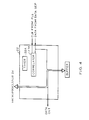
- the synchronization character 34 also allows the controller 22 to determine the boundaries of bytes of information recorded in the sector. At the end of the synchronization character a timer 22A ( Figure 4) is started which is used to time to the remaining header fields and to the next sector header.
- the system using a clock from the PLL 16 which is one-half the bit frequency, as described in US-4908721 entitled A Method of Handling Data From a Storage Device, filed May 12, 1988 which has a common assignee, examines only every other bit.
- s' 1110101101100010, the under-lined portions of s.
- the bits which are interspersed with s' substantially eliminate inter-bit interference caused by, for example, the magnetic flux reversals representing two ONES interacting with each other. Such interference may cause peak shifts, resulting in the PLL 16 taking longer to lock to the correct bit-tracking phase or increased error in data seperating this pattern.
- the preamble 32 can be used to determine the decode group. If, for example, the preamble is a pattern 100100...1 it can be used to determine the boundary of the three-bit decode group. The synchronization character 34 would then be used to determine the byte boundaries.
- the address field 36 contains at least one copy of the sector address, in the preferred embodiment it contains four copies.
- the servo field 38 contains information which is used by the system 8 to center the head on the track.
- the data section contains a data preamble 40 and a data synchronization character 42 which are identical with the preamble 32 and synchronization character 34 in the header.
- a bad sector bit-map which contains information about the good and bad sectors in the track, or a portions of the track.
- the bit-map is redundant in that it is recorded in multiple sectors in the track.
- the bit-maps can be re-written and thus up-dated, that is, as sectors degrade from good to bad the maps can be revised to reflect the degradation. Recording the map in multiple sectors serves to protect the map from loss due to the degradation of any one sector or group of sectors.
- the bit-map is followed by the data and data redundancy symbols.
- the radial contiguous formatting of the disk 28 allows the preamble 32 and the synchronization character 34 to be located, regardless of where the associated head is placed with respect to the tracks. Without radial contiguous formatting, if, for example, the head straddles two tracks, the data signal in one track may be read as canceling the data signal in the other track, that is, a segment in which negative peaks in one track correspond to positive peaks in the other track may be read as a transitionless signal. Thus a DC-erase may be detected in the data section of the sector.
- the acquire mode of the AGC 20 is then enabled, that is, during the detection of a false DC-erase, the acquired gain may cause the read channel to saturate and the system would not recover in time to "see" the real data.
- the synchronization characters 34 and the address fields 36 in a radial contiguous format bit canceling due to an off-center head is eliminated, and thus, each of these fields can be located once a true DC-erase is detected.
- Gray coding the addresses also, allows the address to be determined to within two tracks, even if the head is straddling two tracks.
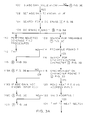
- the system 8 operates in one of two modes during synchronization. If the system has not previously synchronized to the track, the appropriate gain of the read channel for data retrieval from the track is not known. Accordingly, the system first determines the approximate gain ( Figure 3E) before it begins the synchronization process at step 100. However, if the system has previously synchronized to the selected track, the approximate gain for that track has already been determined and stored in an appropriate memory (not shown). The system 8 retrieves that value and adjusts the gain of the AGC 20 to this fixed value. It then begins synchronization (step 102).
- the synchronization process begins with a search for a DC-erase field 30 (step 104).
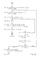
- the search operation is discussed in more detail with reference to Figure 3B below.
- a transitionless signal segment when a transitionless signal segment is detected, it is assumed that it is a DC-erase field (step 106). Thus the start of a sector is assumed found and a "search" for the preamble is started (step 108). It is likely that false DC-erase fields will be frequently found due to an off-center head's "canceling" of data signals. However, if the start of a sector has in fact been detected, the preamble will be detected within a predetermined time thereafter. The preamble will be detected regardless of whether or not the head is centered on the track due to the radially contiguous format of the disk.
- the preamble will not be detected within the predetermined time and the search for the DC-erase field is begun again (steps 114-115).
- the preamble search is described in more detail with reference to Figure 3C below. DC-erase fields are continuously searched for during the preamble search. If another DC-erase field is detected at any time during the preamble search, the search is re-started (Step 166, Figure 3C).
- a search for the synchronization character is begun (step 116).
- the synchronization character will be found within a predetermined time if the previously detected DC-erase field and preamble denote the start of a sector. Sensing of the synchronization character allows the controller 22 to set a sector timer 22A ( Figure 4). The timer 22A is then used to enable controller operations on specific sector segments, for example, the end of the address field and then the start of the servo field, and also to the header section of the next sector. If the synchronization character is not sensed within the specified time, an indication of false detection of the DC-erase field and the preamble, the DC-erase field search is again started (step 119A).
- the synchronization character search is described in more detail with reference to Figure 3D below.
- the DC-erase field search also continues throughout the synchronization character search. If a DC-erase is found at any time, the synchronization process is re-started (step 174A, Figure 3D).
- the address field contains a number of copies of the address, for example, four copies, and if some minimum number of copies match each other, for example two copies, the address is deemed valid.
- the controller 22 uses the sector timer 22A to time and enable the sampling of the servo field 38 and this sampling may then be used to move the head to the center of the track. It then uses the timer 22A to time to the next sector where it expects to find the sector header and enables the acquire modes of both the PLL 16 and AGC 20 in the preamble to synchronize to this next sector. It then reads the sector address field (steps 124-128) and determines the validity of this address by comparing a minimum number of copies to the expected sector address (step 130). Thus if, for example, the first sector found is sector 10 the next sector should be sector 11. If the sector address matches the expected address the head is assumed to be synchronized.
- the system If the address is an invalid address or it does not match the expected address, the system times to the next sector and reads that address to determine which sector is then rotating under the head. If the location of the head cannot be determined in a reasonable number of sectors the system re-starts the DC-erase field search (steps 130-133).
- the DC-erase field, preamble and synchronization character searches are all performed by the controller 22 ( Figure 4).
- the controller 22 receives from the data separator 14 samples of the signal read from the disk.
- the controller 22 examines these samples as a bit-stream and determines if any segment of the signal match the signal pattern for which the controller is then looking. For example, if the controller is conducting the DC-erase field search it will examine the signal segments for a segment without transitions.
- the system controller 22 can vary the number of bit-matches required to detect a synchronization character and/or the number of symbol-matches required to signify a valid address, thus allowing for more or less severe checking. For example, during the factory checking of a drive the controller 22 may require perfect matching, while much less than perfect matching may be required during system error recovery procedures.
- the DC-erase field search is begun by loading all ONES into a correlator, or shift register, 23 in the controller 22 ( Figure 4). Thereafter signal samples from the data separator 14 are shifted into the correlator 23 and the ONES are correspondingly shifted out. Each time a sample is shifted into the correlator 23 the contents are examined to determine if the signal segment represented by the samples contains fewer than some predetermined number of ONES, indicating, with some allowance for error, a transitionless signal segment (step 144). For example, if a forty-bit signal segment is examined, a DC-erase field may be indicated if four or fewer ONES are contained in the correlator 23.
- the controller 22 After detecting a DC-erase field, the controller 22 starts the preamble search (step 108 Figure 3A). With reference to Figure 3C, the controller starts the timer 22A, and initializes the correlator 23 to all ZEROS (step 148). Signal samples are then shifted into the correlator from the data separator 14 and the contents of the correlator are repeatedly compared with the preamble pattern, that is, with a "pattern" of a minimum number of ONES in a predetermined number of bits, where ONES represent transitions, although not necessarily in bit alignment (step 150). The preferred embodiment looks for four ONES in a twelve-bit signal segment.
- the preamble is presumed to have been detected (step 150-152). If, however, the timer 22A reaches time T 1 before a preamble is detected, the synchronization process is re-started with the DC-erase field search (step 170).
- step 152 acquire modes of the AGC 20 and the PLL 16 are enabled. This allows the AGC 20 to determine the appropriate read channel gain for the header section, by feeding back the signal magnitude to set the gain to a constant value, and the PLL 16 to lock to the header bit-frequency and phase. The time to the end of the preamble is sufficient for the AGC 20 and PLL 16, respectively, to lock the appropriate gain and phase (step 154). Thereafter the gain of AGC 20 is held for the remainder of the header and the PLL 16 tracks the frequency and phase of the header data-bits until the end of the address field 36. At this point the AGC gain may be stored for future use by the microprocessor 24.
- PLL 16 is locked to the phase of the reference clock 18 ( Figure 1) because the servo field 38, which follows, does not contain information recorded with the same frequency and phase as the data-bits.
- Timing diagrams for the AGC 20 and the PLL 16 are shown in Figure 2.
- the synchronization character search is started (step 116, Figure 3A). With reference to Figure 3D, this search is begun by initializing the correlator 23 ( Figure 4) with the synchronization character and shifting signal samples from the data separator 14 into the correlator 23 (step 172). The signal segments are then examined for a match with the synchronization character pattern. If the pattern is found before time T 1 ( Figure 2), a synchronization character is deemed detected (steps 174, 176). At the end of the synchronization character the timer 22A is re-started to time to the remaining header fields and to the header section of the next sector (step 178). The timing diagram for the timer is shown in Figure 2. If, however, the synchronization character is not detected before time T 1 , the synchronization process is re-started with a DC-erase field search (step 175).
- a gain value is first determined which allows the gain to be pre-set and the DC-erase field to be detected and the same steps are followed thereafter to complete synchronization (step 100, Figure 3A).
- the gain of the AGC 20 is first set to a maximum value (step 182).
- the timer 22A ( Figure 1) is then started and a search is made for the DC-erase field (step 184).
- the search uses the same steps as the DC-erase field search described above. If a start of sector DC-erase field is not found before time T A , the gain of the AGC 20 is pre-set to another value, the timer 22A is re-started and a search for the DC-erase field is again started (steps 194-198).
- the gain of AGC 20 is stored in an appropriate memory (not shown) so that it may be used the next time the head is switched to that track.
- Pre-setting the gain of the AGC 20 allows the system to simultaneously enable the acquire modes of the AGC 20 and the PLL 16 without having the PLL 16 try to lock to the phase of amplified noise signals, for example, if the gain of the AGC 20 was too high.
- the normal AGC action does not have to correct very far, and it can thus acquire the appropriate gain within a relatively short time. This allows the PLL 16 to operate on almost all of the preamble 32 to acquire phase-lock and the preamble can therefore be relatively short in length.
- the data separator 14 includes a comparator 300 and flip-flops 302 and 304.
- the flip-flops 302,304 are clocked by the PLL 16 which is locked to the reference clock 18 ( Figure 1).
- the signal read from the disk is input to the comparator 300.
- the comparator output is asserted when the signal peak is within a predetermined range, indicating a flux reversal on the disk, which is interpreted as a ONE.
- the asserted output of the comparator is then input to flip-flop 302 and appears at its output.
- flip-flop 302 The output of flip-flop 302 is input to flip-flop 304 when it is clocked by the PLL 16. Flip-flop 302 is then cleared. When flip-flop 304 is next clocked, the contents of the flip-flop are stored in the correlator 23 as a ONE ( Figure 4). If the signal peaks do not come within the predetermined amplitude range, the output of flip-flop 302 remains de-asserted and ZEROS are input to the correlator 23.
Landscapes
- Engineering & Computer Science (AREA)
- Signal Processing (AREA)
- Signal Processing For Digital Recording And Reproducing (AREA)
Description
Claims (15)
- A magnetic disk system comprising:characterized in that :A) a plurality of magnetic disks, on a common spindle, for recording signals representing binary data, each of said disks comprising:1) a plurality of concentric tracks (29A,29C), each of said tracks comprising a plurality of sectors,2) each of said sectors comprising a header section (28A) and a data section (28B), said header section having a leading end and a trailing end, said trailing end of said header section being adjacent to the leading end of said data section,3) said header section having a plurality of magnetically recorded fields (30-38) including, in order,a) a preamble field (32) having recorded therein a series of signals suitable for synchronization of a clock (18) to bits recorded in said header section (28A), andb) a synchronization field (34) containing a synchronization character suitable for synchronizing reading operations with group and byte boundaries of information recorded in said header section;c) an address field (36) containing the address of said sector;4) at least one of said header sections (28A) in each of said tracks including a DC-erase field (30) disposed adjacent to said leading end of said header section (28A) and comprising a transitionless signal segment;B) a read write head for sensing flux transitions on said disk;C) a DC-erase detector (22) for detecting said DC-erase field (30) from the output of said read write head;D) means (22) responsive to the detection of said DC-erase field for detecting said preamble (32) in the output of said read write head;E) means (22) responsive to the detection of said DC-erase field (30) and said preamble (32) for detecting said synchronization character (34);F) a clock (CLK) for providing timing signals corresponding to the retrieval of bits, groups and bytes from said disk;G) synchronizing means (22)1) responsive to said preamble (32) for synchronizing said clock (CLK) to the bits recorded on said disk, and2) responsive to said synchronization character for synchronizing said clock to group and byte boundaries of information recorded on said disk;
said header section (28A) further includes a servo field (38) following said address field (36), said servo field containing a recorded signal for use in a servo system that maintains the position of said read write head over said track. - The system defined in claim 1 in which each of said sectors includes in its data section (28B), a sector map section (44), said sector map section containing information concerning which sectors in the track are defective.
- The magnetic disk defined in claim 1 or claim 2 in which said sector map (44) contains information concerning a number of sectors in the track.
- The magnetic disk defined in claim 1, claim 2 or claim 3 in which said bad sector map is updated when a previously non-defective sector becomes defective.
- The system defined in claim 1 in which said clock clocks a timer (22A) to provide timing signals (22D) for timing sector fields successive to said synchronization field (34) and including means for synchronizing said timing signals to the detection of said synchronization character.
- The system defined in claim 5 in which said timer (22A) further provides timing signals for timing the detection of said preamble, and if said preamble is not detected within a predetermined time said preamble detecting means is responsive to the detection of a next DC-erase field.
- The system defined in claim 6 in which said timer (22A) additionally provides timing signals for timing the detection of said synchronization character, and if said synchronization character is not detected within a predetermined time said synchronization character detecting means (22) is responsive to the detection of a next DC-erase field and a next preamble.
- The system defined in claim 6 wherein said preamble detecting means (22) is further responsive to the detection of more than one DC-erase field within said preamble and successive sections of said header section.
- The magnetic disk system of claim 1 wherein said DC-erase detector (22) detects said DC-erase field by detecting a number of flux transitions below a predetermined threshold.
- The magnetic disk system of claim 9 wherein said threshold is selected from a number of predetermined thresholds such that the threshold can be raised if no DC-erase fields are detected within a predetermined period of time or lowered if more than a predetermined number of DC-erase fields are detected within a predetermined period of time.
- The magnetic disk system of claim 1 wherein said synchronization field detection means (22) detects said synchronization field by detecting a series of flux transitions corresponding to a synchronization character to within a predetermined threshold number of transitions.
- The magnetic disk system of claim 11 wherein said threshold is selected from a number of predetermined thresholds such that the threshold can be raised if no synchronization fields are detected within a predetermined period of time or lowered if more than a predetermined number of synchronization fields are detected within a predetermined period of time.
- The magnetic disk system of claim 1 further comprising a phase-locked loop (16) which acquires the phase and frequency of the flux transitions during said preamble field (32), said phase-locked loop switching to the phase of a reference clock (18) during said servo field (38) wherein said clock (CLK) is synchronized to the reference clock (18) until the end of said header section.
- The system as defined in claim 1 wherein the system includes a servo system responsive to said synchronizing means (22) for interpreting said servo information in said servo field and centering said read/write head on a track.
- The system defined in claim 1 wherein the header section of each sector is recorded in a radially contiguous format on the disk to thereby enable the preamble field (32) and the synchronization field (34) and the address field (36) to be located regardless of whether the read/write head straddles two tracks.
Applications Claiming Priority (2)
| Application Number | Priority Date | Filing Date | Title |
|---|---|---|---|
| US07/193,090 US5036408A (en) | 1988-05-12 | 1988-05-12 | High efficiency disk format and synchronization system |
| US193090 | 1988-05-12 |
Publications (3)
| Publication Number | Publication Date |
|---|---|
| EP0341852A2 EP0341852A2 (en) | 1989-11-15 |
| EP0341852A3 EP0341852A3 (en) | 1991-12-27 |
| EP0341852B1 true EP0341852B1 (en) | 1998-01-07 |
Family
ID=22712246
Family Applications (1)
| Application Number | Title | Priority Date | Filing Date |
|---|---|---|---|
| EP89304048A Expired - Lifetime EP0341852B1 (en) | 1988-05-12 | 1989-04-24 | High efficiency disk format and synchronization system |
Country Status (6)
| Country | Link |
|---|---|
| US (1) | US5036408A (en) |
| EP (1) | EP0341852B1 (en) |
| JP (1) | JPH0218759A (en) |
| CA (1) | CA1310111C (en) |
| DE (1) | DE68928518T2 (en) |
| SG (1) | SG49105A1 (en) |
Cited By (1)
| Publication number | Priority date | Publication date | Assignee | Title |
|---|---|---|---|---|
| US7134068B2 (en) | 2003-12-04 | 2006-11-07 | Seagate Technology Llc | Channel processing data without leading sync mark |
Families Citing this family (65)
| Publication number | Priority date | Publication date | Assignee | Title |
|---|---|---|---|---|
| JPH0821213B2 (en) * | 1988-08-05 | 1996-03-04 | 富士通株式会社 | Sector servo information detection method |
| US5274772A (en) * | 1989-06-28 | 1993-12-28 | International Business Machines Corporation | Data processing systems having means for selectively combining records into signal blocks for recording in a record medium |
| JP2783369B2 (en) * | 1989-12-22 | 1998-08-06 | シーゲイト テクノロジー インターナショナル | Method and apparatus for reproducing and restoring data of failed channel in parallel transmission device |
| JPH0785285B2 (en) * | 1989-12-28 | 1995-09-13 | 株式会社東芝 | Magnetic recording / reproducing device |
| DE4018605A1 (en) * | 1990-06-09 | 1991-12-12 | Thomson Brandt Gmbh | RECORDER FOR DIGITAL SIGNALS |
| US5420730A (en) * | 1990-08-17 | 1995-05-30 | Moon; Ronald R. | Servo data recovery circuit for disk drive having digital embedded sector servo |
| JP2546076B2 (en) * | 1991-02-27 | 1996-10-23 | 日本ビクター株式会社 | Magnetic recording correction circuit |
| DE69231731T2 (en) * | 1991-06-17 | 2001-06-28 | Sony Corp., Tokio/Tokyo | Plate recording process |
| JP3277517B2 (en) * | 1991-06-17 | 2002-04-22 | ソニー株式会社 | Method of reproducing disc-shaped recording medium |
| JP2625609B2 (en) * | 1991-07-10 | 1997-07-02 | インターナショナル・ビジネス・マシーンズ・コーポレイション | Disk storage device |
| US5517371A (en) * | 1991-10-18 | 1996-05-14 | Teac Corporation | Track sector detection system for rotating disk data storage apparatus |
| US5416760A (en) * | 1991-12-16 | 1995-05-16 | Advanced Micro Devices, Inc. | Recovery of data from optical data disk sectors having missing or defective synchronization information |
| US5293276A (en) * | 1992-01-24 | 1994-03-08 | Fujitsu Limited | Method for generating a reference signal from unique servo mark pattern detection |
| DE69324518T2 (en) * | 1992-02-28 | 1999-08-26 | Ampex Systems Corp. | System areas for tape loading operations |
| JP2574106B2 (en) * | 1992-09-01 | 1997-01-22 | 富士通株式会社 | Clock recovery circuit for magnetic disk drive |
| US5365382A (en) * | 1993-05-18 | 1994-11-15 | Digital Equipment Corporation | Synchronization to different fields in a storage device |
| JP3240762B2 (en) * | 1993-07-26 | 2001-12-25 | ソニー株式会社 | Optical recording medium reproducing method and reproducing apparatus |
| WO1995007532A1 (en) * | 1993-09-07 | 1995-03-16 | Sony Corporation | Disk device |
| US5666238A (en) * | 1993-12-28 | 1997-09-09 | Kabushiki Kaisha Toshiba | Data sector control apparatus and method for disk storage system |
| US5568627A (en) * | 1994-04-05 | 1996-10-22 | Quantum Corporation | Header verification in a disk drive using sector histories for improved format efficiency |
| CN1106640C (en) * | 1994-08-25 | 2003-04-23 | 索尼公司 | Optical disk and optical disk drive device |
| US5661760A (en) * | 1995-10-23 | 1997-08-26 | Quantum Corporation | Wide biphase digital servo information detection, and estimation for disk drive using servo Viterbi detector |
| US5862005A (en) * | 1994-10-11 | 1999-01-19 | Quantum Corporation | Synchronous detection of wide bi-phase coded servo information for disk drive |
| US5717535A (en) * | 1995-01-25 | 1998-02-10 | Seagate Technology, Inc. | Block address integrity check for storage medium |
| US6181497B1 (en) | 1995-12-12 | 2001-01-30 | International Business Machines Corporation | System and method for providing nonadjacent redundancy synchronization bytes |
| US5926336A (en) * | 1996-09-13 | 1999-07-20 | Samsung Electronics Co., Ltd. | Method and apparatus for rewriting servo information on a disk in a hard disk assembly |
| US5995308A (en) * | 1997-03-31 | 1999-11-30 | Stmicroelectronics N.V. | Disk resident defective data sector information management system on a headerless magnetic disk device |
| WO1998052287A2 (en) * | 1997-05-14 | 1998-11-19 | Seagate Technology, Inc. | Signal space detector for channels utilizing a code having time varying constraints |
| US6212661B1 (en) | 1997-08-11 | 2001-04-03 | Seagate Technology, Inc. | Static viterbi detector for channels utilizing a code having time varying constraints |
| US6098185A (en) * | 1997-10-31 | 2000-08-01 | Stmicroelectronics, N.V. | Header-formatted defective sector management system |
| US6493162B1 (en) | 1997-12-05 | 2002-12-10 | Seagate Technology Llc | Frame synchronization for viterbi detector |
| US6404573B1 (en) * | 1998-05-13 | 2002-06-11 | Seagate Technology Llc | Full and half-rate signal space detection for channels with a time-varying MTR |
| JPH11353811A (en) * | 1998-06-09 | 1999-12-24 | Sony Corp | Digital data recording method, recording device, reproducing device, and magnetic tape |
| US6429994B1 (en) | 1998-08-14 | 2002-08-06 | Samsung Electronics Co., Ltd | Method and apparatus for providing servo gain linearization for a magneto-resistive head |
| US6441988B2 (en) | 1998-10-07 | 2002-08-27 | Samsung Electronics Co., Ltd. | Method and apparatus for reducing acoustic noise in a hard disk drive |
| US6704354B1 (en) | 1998-10-16 | 2004-03-09 | Samsung Electronics Co., Ltd. | Method and apparatus of providing adaptive equalization using sign permutation filtering |
| US6577687B2 (en) * | 1998-12-23 | 2003-06-10 | Maxtor Corporation | Method for transmitting data over a data bus with minimized digital inter-symbol interference |
| US6185059B1 (en) | 1998-12-23 | 2001-02-06 | Quantum Corp. | Method of controlling a disk drive for eliminating blanking intervals formed on a storage disk positioned within the drive |
| US6687079B1 (en) | 1999-10-08 | 2004-02-03 | Samsung Electronics Co., Ltd | Apparatus and method for providing servo gain linearization for a magneto-resistive head |
| US6549364B1 (en) | 1999-12-15 | 2003-04-15 | Samsung Electronics Co., Ltd. | Optimization method and apparatus for a generalized fourier seek trajectory for a hard disk drive servomechanism |
| US6501613B1 (en) | 1999-12-15 | 2002-12-31 | Samsung Electronics Co., Ltd. | Generalized Fourier seek method and apparatus for a hard disk drive servomechanism |
| US6801384B2 (en) | 2000-09-14 | 2004-10-05 | Samsung Electronics Co., Ltd. | Voltage-constrained sinusoidal seek servo in hard disk drives |
| US6906883B2 (en) * | 2000-09-14 | 2005-06-14 | Samsung Electronics Ltd., Co. | Servo defect management scheme in hard disk drives |
| US6791778B2 (en) | 2000-09-14 | 2004-09-14 | Samsung Electronics Co., Inc. | Method and apparatus to detect and manage servo sectors with defect on servo pattern area in hard disk drives |
| US6744590B2 (en) | 2000-09-14 | 2004-06-01 | Samsung Electronics Co., Inc. | Seek trajectory adaptation in sinusoidal seek servo hard disk drives |
| JP4644356B2 (en) | 2000-11-10 | 2011-03-02 | 株式会社日立グローバルストレージテクノロジーズ | Servo write system for magnetic disk device and magnetic recording / reproducing device |
| US6762902B2 (en) | 2000-12-15 | 2004-07-13 | Samsung Electronics Co., Ltd. | Time-varying, non-synchronous disturbance identification and cancellation in a rotating disk storage device |
| US6700731B2 (en) * | 2001-05-31 | 2004-03-02 | Samsung Electronics Co., Inc. | In-situ linearization of magnetic read/write head transducer position error signal |
| US7382568B2 (en) * | 2001-06-28 | 2008-06-03 | Stmicroelectronics, Inc. | Circuit and method for detecting a servo wedge on spin-up of a data-storage disk |
| US7027247B2 (en) | 2001-06-28 | 2006-04-11 | Stmicroelectronics, Inc. | Servo circuit having a synchronous servo channel and method for synchronously recovering servo data |
| US7430082B2 (en) | 2001-06-28 | 2008-09-30 | Stmicroelectronics, Inc. | Circuit and method for demodulating a servo position burst |
| US7206149B2 (en) * | 2001-06-28 | 2007-04-17 | Stmicroelectronics, Inc. | Circuit and method for detecting a spin-up wedge and a corresponding servo wedge on spin up of a data-storage disk |
| US7830630B2 (en) * | 2001-06-28 | 2010-11-09 | Stmicroelectronics, Inc. | Circuit and method for detecting the phase of a servo signal |
| US7839594B2 (en) * | 2001-06-28 | 2010-11-23 | Stmicroelectronics, Inc. | Data-storage disk having few or no spin-up wedges and method for writing servo wedges onto the disk |
| US7158330B2 (en) | 2001-11-08 | 2007-01-02 | Samsung Electronics Co., Ltd. | Method and apparatus for servo track writing by track following on a dedicated servo disk on a fluid spindle bearing |
| JP4133474B2 (en) * | 2003-03-13 | 2008-08-13 | 富士通株式会社 | Information recording / reproducing apparatus, signal recording / reproducing circuit, and information recording / reproducing method |
| FR2850182B1 (en) * | 2003-06-10 | 2006-02-24 | Garnier Jean | METHOD FOR MANAGING A DIGITAL STORAGE UNIT |
| EP1603134A1 (en) * | 2004-05-31 | 2005-12-07 | STMicroelectronics S.r.l. | Method to improve data reliability on hard disk drive systems |
| JP2006031742A (en) * | 2004-07-12 | 2006-02-02 | Fujitsu Ltd | Magnetic disk unit |
| JP4148951B2 (en) * | 2005-01-12 | 2008-09-10 | 株式会社東芝 | Magnetic recording / reproducing device |
| JP2007102960A (en) * | 2005-10-06 | 2007-04-19 | Hitachi Global Storage Technologies Netherlands Bv | Magnetic disk unit |
| US7738202B1 (en) | 2005-10-07 | 2010-06-15 | Seagate Technology, Llc | Wide-biphase-detector quality monitor for sensing of pin layer reversal |
| US8159768B1 (en) | 2008-06-25 | 2012-04-17 | Western Digital Technologies, Inc. | Detecting a servo address mark (SAM) in a servo field sync-up operation |
| US9047921B2 (en) * | 2009-11-19 | 2015-06-02 | HGST Netherlands B.V. | Adjusting recording density in a circumferential direction |
| WO2013077811A1 (en) * | 2011-11-21 | 2013-05-30 | Agency For Science, Technology And Research | Data storage device and method for generating a reference clock signal for data storage device |
Citations (2)
| Publication number | Priority date | Publication date | Assignee | Title |
|---|---|---|---|---|
| EP0166373A1 (en) * | 1984-06-22 | 1986-01-02 | Bull HN Information Systems Inc. | Disk subsystem read write control |
| EP0212099A2 (en) * | 1985-07-29 | 1987-03-04 | International Business Machines Corporation | Sector identification method for hard sectored hard files |
Family Cites Families (8)
| Publication number | Priority date | Publication date | Assignee | Title |
|---|---|---|---|---|
| US3534344A (en) * | 1967-12-21 | 1970-10-13 | Ibm | Method and apparatus for recording and detecting information |
| US3893180A (en) * | 1974-01-02 | 1975-07-01 | Honeywell Inf Systems | Transducer positioning system |
| NL7801041A (en) * | 1978-01-30 | 1979-08-01 | Philips Nv | PROCEDURE FOR ADDRESSING AND / OR RETRIEVING INFORMATION ON A REGISTRATION CARRIER. |
| JPS57103563A (en) * | 1980-12-19 | 1982-06-28 | Hitachi Ltd | Disk controller |
| US4424543A (en) * | 1981-11-16 | 1984-01-03 | Dma Systems Corporation | Method and apparatus for recording transducer positioning information |
| JPS59165279A (en) * | 1983-03-11 | 1984-09-18 | Toshiba Corp | Positioning system of head |
| JPS59229708A (en) * | 1983-06-10 | 1984-12-24 | Toshiba Corp | Picture information recorder |
| JPS60254463A (en) * | 1984-05-31 | 1985-12-16 | Sony Corp | Digital data recording or playback method |
-
1988
- 1988-05-12 US US07/193,090 patent/US5036408A/en not_active Expired - Lifetime
-
1989
- 1989-04-24 DE DE68928518T patent/DE68928518T2/en not_active Expired - Fee Related
- 1989-04-24 EP EP89304048A patent/EP0341852B1/en not_active Expired - Lifetime
- 1989-04-24 SG SG1996006028A patent/SG49105A1/en unknown
- 1989-05-11 CA CA000599494A patent/CA1310111C/en not_active Expired - Fee Related
- 1989-05-12 JP JP1120239A patent/JPH0218759A/en active Pending
Patent Citations (2)
| Publication number | Priority date | Publication date | Assignee | Title |
|---|---|---|---|---|
| EP0166373A1 (en) * | 1984-06-22 | 1986-01-02 | Bull HN Information Systems Inc. | Disk subsystem read write control |
| EP0212099A2 (en) * | 1985-07-29 | 1987-03-04 | International Business Machines Corporation | Sector identification method for hard sectored hard files |
Cited By (1)
| Publication number | Priority date | Publication date | Assignee | Title |
|---|---|---|---|---|
| US7134068B2 (en) | 2003-12-04 | 2006-11-07 | Seagate Technology Llc | Channel processing data without leading sync mark |
Also Published As
| Publication number | Publication date |
|---|---|
| JPH0218759A (en) | 1990-01-23 |
| EP0341852A2 (en) | 1989-11-15 |
| US5036408A (en) | 1991-07-30 |
| EP0341852A3 (en) | 1991-12-27 |
| DE68928518T2 (en) | 1998-07-30 |
| SG49105A1 (en) | 1998-05-18 |
| DE68928518D1 (en) | 1998-02-12 |
| CA1310111C (en) | 1992-11-10 |
Similar Documents
| Publication | Publication Date | Title |
|---|---|---|
| US5036408A (en) | High efficiency disk format and synchronization system | |
| US6124994A (en) | System and method for providing nonadjacent redundancy synchronization bytes | |
| US5253131A (en) | Servo pattern for location and positioning of information on a disk drive | |
| US4862295A (en) | Method of formatting a storage medium and drive unit for controlling the reading and writing of data on the formatted storage medium | |
| US5231545A (en) | Fault tolerant rll data sector address mark decoder | |
| US5321560A (en) | Embedded servo system for low power disk drives | |
| US6557113B1 (en) | Synchronization recovery technique for storage media | |
| EP0164746B1 (en) | Optical information recording and reproducing apparatus and optical disc | |
| EP0660307A2 (en) | Sampled data channel servo detector using PRML techniques | |
| EP0269381A2 (en) | Sampled servo code format and system for a disc drive | |
| JPH07169186A (en) | Method and apparatus for positioning of beginning of specific data block at inside of user data block segment in disk drive as well as disk drive architecture | |
| US5963387A (en) | Method for forming and processing data address mark for hard disk drive | |
| US5418657A (en) | Track address detecting means by HDD sector servo method | |
| US6058084A (en) | Disk-shaped recording medium using segment ID and disk unit using the disk-shaped recording medium | |
| EP0490400B1 (en) | Information storage apparatus | |
| US6690524B1 (en) | Data recovery in a disc drive with redundant sync data blocks | |
| US6972917B2 (en) | Signal processing technique for preventing delay in read time from retry operations | |
| US6097561A (en) | Data recovery in a disc drive with redundant sync data blocks | |
| JPH10269715A (en) | Disk reproducing apparatus and disk reproducing method | |
| JP2589673B2 (en) | Address data detection device | |
| KR100269164B1 (en) | Synchronization signal detection method | |
| JPH0834047B2 (en) | Magnetic recording / reproducing device | |
| JPH0574051A (en) | Sync information detector | |
| JPS634479A (en) | Optical disk processing system | |
| JPH0756690A (en) | Disk device read / write device |
Legal Events
| Date | Code | Title | Description |
|---|---|---|---|
| PUAI | Public reference made under article 153(3) epc to a published international application that has entered the european phase |
Free format text: ORIGINAL CODE: 0009012 |
|
| 17P | Request for examination filed |
Effective date: 19890516 |
|
| AK | Designated contracting states |
Kind code of ref document: A2 Designated state(s): DE FR GB IT NL |
|
| PUAL | Search report despatched |
Free format text: ORIGINAL CODE: 0009013 |
|
| AK | Designated contracting states |
Kind code of ref document: A3 Designated state(s): DE FR GB IT NL |
|
| 17Q | First examination report despatched |
Effective date: 19940914 |
|
| RAP1 | Party data changed (applicant data changed or rights of an application transferred) |
Owner name: QUANTUM CORPORATION |
|
| GRAG | Despatch of communication of intention to grant |
Free format text: ORIGINAL CODE: EPIDOS AGRA |
|
| GRAG | Despatch of communication of intention to grant |
Free format text: ORIGINAL CODE: EPIDOS AGRA |
|
| GRAH | Despatch of communication of intention to grant a patent |
Free format text: ORIGINAL CODE: EPIDOS IGRA |
|
| GRAH | Despatch of communication of intention to grant a patent |
Free format text: ORIGINAL CODE: EPIDOS IGRA |
|
| GRAA | (expected) grant |
Free format text: ORIGINAL CODE: 0009210 |
|
| AK | Designated contracting states |
Kind code of ref document: B1 Designated state(s): DE FR GB IT NL |
|
| REF | Corresponds to: |
Ref document number: 68928518 Country of ref document: DE Date of ref document: 19980212 |
|
| ITF | It: translation for a ep patent filed | ||
| ET | Fr: translation filed | ||
| PLBE | No opposition filed within time limit |
Free format text: ORIGINAL CODE: 0009261 |
|
| STAA | Information on the status of an ep patent application or granted ep patent |
Free format text: STATUS: NO OPPOSITION FILED WITHIN TIME LIMIT |
|
| 26N | No opposition filed | ||
| PGFP | Annual fee paid to national office [announced via postgrant information from national office to epo] |
Ref country code: NL Payment date: 19990331 Year of fee payment: 11 Ref country code: FR Payment date: 19990331 Year of fee payment: 11 |
|
| PG25 | Lapsed in a contracting state [announced via postgrant information from national office to epo] |
Ref country code: NL Free format text: LAPSE BECAUSE OF NON-PAYMENT OF DUE FEES Effective date: 20001101 |
|
| PG25 | Lapsed in a contracting state [announced via postgrant information from national office to epo] |
Ref country code: FR Free format text: LAPSE BECAUSE OF NON-PAYMENT OF DUE FEES Effective date: 20001229 |
|
| NLV4 | Nl: lapsed or anulled due to non-payment of the annual fee |
Effective date: 20001101 |
|
| REG | Reference to a national code |
Ref country code: FR Ref legal event code: ST |
|
| PGFP | Annual fee paid to national office [announced via postgrant information from national office to epo] |
Ref country code: DE Payment date: 20010402 Year of fee payment: 13 |
|
| PGFP | Annual fee paid to national office [announced via postgrant information from national office to epo] |
Ref country code: GB Payment date: 20010403 Year of fee payment: 13 |
|
| REG | Reference to a national code |
Ref country code: GB Ref legal event code: IF02 |
|
| PG25 | Lapsed in a contracting state [announced via postgrant information from national office to epo] |
Ref country code: GB Free format text: LAPSE BECAUSE OF NON-PAYMENT OF DUE FEES Effective date: 20020424 |
|
| PG25 | Lapsed in a contracting state [announced via postgrant information from national office to epo] |
Ref country code: DE Free format text: LAPSE BECAUSE OF NON-PAYMENT OF DUE FEES Effective date: 20021101 |
|
| GBPC | Gb: european patent ceased through non-payment of renewal fee |
Effective date: 20020424 |
|
| PG25 | Lapsed in a contracting state [announced via postgrant information from national office to epo] |
Ref country code: IT Free format text: LAPSE BECAUSE OF NON-PAYMENT OF DUE FEES;WARNING: LAPSES OF ITALIAN PATENTS WITH EFFECTIVE DATE BEFORE 2007 MAY HAVE OCCURRED AT ANY TIME BEFORE 2007. THE CORRECT EFFECTIVE DATE MAY BE DIFFERENT FROM THE ONE RECORDED. Effective date: 20050424 |