EP0341750A2 - Bogenkolben und Hochdruckentladungslampe mit einem solchen Kolben - Google Patents
Bogenkolben und Hochdruckentladungslampe mit einem solchen Kolben Download PDFInfo
- Publication number
- EP0341750A2 EP0341750A2 EP89108641A EP89108641A EP0341750A2 EP 0341750 A2 EP0341750 A2 EP 0341750A2 EP 89108641 A EP89108641 A EP 89108641A EP 89108641 A EP89108641 A EP 89108641A EP 0341750 A2 EP0341750 A2 EP 0341750A2
- Authority
- EP
- European Patent Office
- Prior art keywords
- arc tube
- feedthrough member
- envelope
- seal
- frit material
- Prior art date
- Legal status (The legal status is an assumption and is not a legal conclusion. Google has not performed a legal analysis and makes no representation as to the accuracy of the status listed.)
- Withdrawn
Links
Images


Classifications
-
- H—ELECTRICITY
- H01—ELECTRIC ELEMENTS
- H01J—ELECTRIC DISCHARGE TUBES OR DISCHARGE LAMPS
- H01J61/00—Gas-discharge or vapour-discharge lamps
- H01J61/02—Details
- H01J61/36—Seals between parts of vessels; Seals for leading-in conductors; Leading-in conductors
- H01J61/361—Seals between parts of vessel
- H01J61/363—End-disc seals or plug seals
Definitions
- the present invention relates to arc tubes, and more particularly to arc tubes used in high pressure metal vapor discharge lamps.
- High pressure metal vapor discharge lamps of the high pressure sodium type operate at seal temperatures of about 700°C. Although such lamp has very high luminous efficiency, the color of the light output is not satisfactory for many applications. Thus, there is a need to improve the color of such HPS lamps.
- said means for sealing said arc tube envelope comprises a seal button at each end of said envelope, said seal button having an aperture therethrough for receiving a feedthrough member and frit material sealing said seal buttons to the ends of said envelope and said feedthrough members into said seal buttons and/or the arc tube envelope.
- the means for interrupting the seal interface between said feedthrough member and said frit material around the total circumference of at least a portion of the feedthrough member comprises a coating disposed around the total periphery, or circumference, of at least a portion the feedthrough member.
- Such coating comprises a material, most preferably a metal or metal alloy, which is inert to reaction with the frit material, the feedthrough member, and the fill gas components during lamp operation and which has thermal expansion properties compatible with the thermal expansion properties of both the feedthrough member and the frit material.
- the means for interrupting the seal interface between said feedthrough member and said frit material around the total circumference of at least a portion of the feedthrough member comprises a coating disposed between said feedthrough member and said sealing frit material, said coating being disposed around the periphery of the feedthrough member.
- Such coating comprises a material which is inert to reaction with the frit material, the feedthrough member, and the fill gas components during lamp operation and which has thermal expansion properties compatible with those of the materials the coating is in contact with.
- the coating comprises molybdenum.
- the coating disposed on the outer surface of the feedthrough member forms a break, or discontinuity, in the seal interface between the feedthrough member and the frit material along the length dimension Y of the feedthrough member.
- the break in the seal interface occurs around the outer perimeter of the feedthrough member.
- the coating comprises a band of coating material disposed between the feedthrough member and the frit material and around the circumference of the feedthrough member.
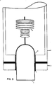
- the arc tube shown in Figure 1 is of a monolithic design.
- arc tube shown in Figures 1 - 3 is of a monolithic design
- the present invention is also advantageous when included in arc tubes fabricated using the hat or disk design.
- Such arc tube designs are well known to those in the lighting art. Examples of such designs are illustrated in Figures 1b, c, of, and described in, U.S. Patent No. 4,713,580 to Schoene, which is hereby incorporated herin by reference.
- the seal button may further be of a hat design.
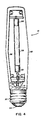
- Figure 2 illustrates an alternative embodiment of the present invention.
- FIG 2 there is shown, in cross-section, the end structure of an arc tube of an alternative embodiment of the present invention.
- the feedthrough member 1 having an electrode 2 mounted thereto is sealed into a ceramic seal button 3 and the arc tube 4 with fused frit material 5.
- Fused frit material 5 also seals the ceramic seal button 3 to the arc tube envelope 4.
- the embodiment of the present invention shown in Figure 2 includes means for interrupting the seal interface between said feedthrough member and said frit material around the total circumference of at least a portion of the feedthrough member.
- the interruption means shown in Figure 2 comprises a coating 6 disposed between the feedthrough member and the sealing frit material and around the total circumference of at least a portion of the feedthrough member.
- the coating is further disposed over the entire outer surface of the niobium feedthrough member.
- the coating shown in Figure 2 interrupts the seal interface between the feedthrough member and the frit material and also protects the portion of the feedthrough extending into the arc tube interior from reaction with the fill gas components.
- Figure 3 illustrates a still further alternative embodiment of the present invention.
- FIG 3 there is shown, in cross-section, the end structure of an arc tube of one embodiment of the present invention.
- the feedthrough member 1 having an electrode 2 mounted thereto is sealed into a ceramic seal button 3 and the arc tube envelope 4 with fused frit material 5.
- Fused frit material 5 also seals the ceramic seal button 3 to the arc tube 4.
- the embodiment of the present invention shown in Figure 3 includes means for interrupting the seal interface between said feedthrough member and said frit material around the total circumference of at least a portion of the feedthrough member comprising a coating 6 disposed around the periphery of the feedthrough member between the feedthrough member and frit material.
- the coating disposed on the outer surface of the feedthrough member interrupts the direct seal interface between the feedthrough member and frit material around at least a portion of the periphery of the feedthrough member.
- the coating is further disposed over the portion of the surface of the feedthrough member projecting from the seal area and into the arc tube.
- the present invention is particularly advantageous for use in ceramic arc tubes containing fills which cause a high pressure metal vapor discharge lamp to operate at temperatures greater than or equal to about 900°C, which is higher than the operating temperatures of typical HPS lamps. Such higher temperatures include temperatures from about 900° to about 1100°C, or higher.
- conventionally fabricated high pressure metal vapor discharge lamps of the high pressure type operating at such high temperatures undergo a variety of undesirable reactions leading to lamp failure.
- sealing material also referred to herein as frit material or frit
- frit material composed of the oxides of aluminum, calcium, magnesium, barium, and boron
- niobium feedthrough can react with the niobium feedthrough to form a reaction zone of three layers: (1) calcium aluminum niobium oxide (next to the frit); (2) niobium boride; and (3) calcium magnesium niobium oxide (adjacent to and derived from the feedthrough member). Failure of the seal is believed to occur at the poorly bonded interface joining the latter two layers. Borate is the seal component which is believed to be responsible for supplying the oxygen to oxidize the feedthrough material.
- control arc tubes were fabricated and tested in a manner similar to that described above, except that the arc tubes of the control experiments did not include a molybdenum coating on the in-lead.
- the control arc tubes began to leak fill after an average of only 120 hours of testing. After 300 hours, all of the control arc tubes had lost at least 20% of their metallic fill.
- a third set of experiments was carried out involving three control lamps and three lamps including a molybdenum coating on the feedthrough member as shown in Figure 3.
- the lamps used in this third set of experiments were fabricated in a manner similar to that described in Example 2, with the exception that one of the lamps including a molybdenum coating had the sodium and mercury dosing increased to 0.6 mg and 11 mg, respectively.
Landscapes
- Vessels And Coating Films For Discharge Lamps (AREA)
Applications Claiming Priority (2)
| Application Number | Priority Date | Filing Date | Title |
|---|---|---|---|
| US19398888A | 1988-05-13 | 1988-05-13 | |
| US193988 | 1988-05-13 |
Publications (2)
| Publication Number | Publication Date |
|---|---|
| EP0341750A2 true EP0341750A2 (de) | 1989-11-15 |
| EP0341750A3 EP0341750A3 (de) | 1991-04-17 |
Family
ID=22715876
Family Applications (1)
| Application Number | Title | Priority Date | Filing Date |
|---|---|---|---|
| EP19890108641 Withdrawn EP0341750A3 (de) | 1988-05-13 | 1989-05-12 | Bogenkolben und Hochdruckentladungslampe mit einem solchen Kolben |
Country Status (4)
| Country | Link |
|---|---|
| US (1) | US5001396A (de) |
| EP (1) | EP0341750A3 (de) |
| JP (1) | JPH0265046A (de) |
| CA (1) | CA1311012C (de) |
Cited By (7)
| Publication number | Priority date | Publication date | Assignee | Title |
|---|---|---|---|---|
| US5404078A (en) * | 1991-08-20 | 1995-04-04 | Patent-Treuhand-Gesellschaft Fur Elektrische Gluhlampen Mbh | High-pressure discharge lamp and method of manufacture |
| EP0926700A3 (de) * | 1997-12-24 | 1999-12-08 | Ngk Insulators, Ltd. | Hochdruckentladungslampe |
| EP1001451A1 (de) * | 1998-11-10 | 2000-05-17 | Osram Sylvania Inc. | Barium enthaltende Bogenentladungslampe mit einer Bogenröhre aus Yttrium-, Gadolinium- oder Terbiumoxide |
| EP1043753A1 (de) * | 1999-04-09 | 2000-10-11 | W.C. Heraeus GmbH & Co. KG | Metallisches Bauteil und Entladungslampe |
| US6169366B1 (en) | 1997-12-24 | 2001-01-02 | Ngk Insulators, Ltd. | High pressure discharge lamp |
| WO2004049390A3 (en) * | 2002-11-25 | 2006-02-16 | Philips Intellectual Property | Ceramic disharge vessel with an end part tightening coating layer |
| WO2007017714A1 (en) * | 2005-08-10 | 2007-02-15 | Koninklijke Philips Electronics N.V. | An electric discharge lamp |
Families Citing this family (11)
| Publication number | Priority date | Publication date | Assignee | Title |
|---|---|---|---|---|
| US5150017A (en) * | 1991-06-27 | 1992-09-22 | Gte Products Corporation | High pressure sodium discharge lamp |
| JP3399103B2 (ja) * | 1994-07-25 | 2003-04-21 | 日本電池株式会社 | 不飽和蒸気圧形高圧ナトリウムランプ |
| US20020117965A1 (en) * | 2001-02-23 | 2002-08-29 | Osram Sylvania Inc. | High buffer gas pressure ceramic arc tube and method and apparatus for making same |
| US6873108B2 (en) * | 2001-09-14 | 2005-03-29 | Osram Sylvania Inc. | Monolithic seal for a sapphire metal halide lamp |
| US7215081B2 (en) * | 2002-12-18 | 2007-05-08 | General Electric Company | HID lamp having material free dosing tube seal |
| US7525252B2 (en) * | 2002-12-27 | 2009-04-28 | General Electric Company | Sealing tube material for high pressure short-arc discharge lamps |
| US20060001346A1 (en) * | 2004-06-30 | 2006-01-05 | Vartuli James S | System and method for design of projector lamp |
| JP4958067B2 (ja) * | 2006-11-30 | 2012-06-20 | Toto株式会社 | 水栓装置 |
| US7741780B2 (en) * | 2007-02-26 | 2010-06-22 | Osram Sylvania Inc. | Ceramic discharge vessel having a sealing composition |
| US8310157B2 (en) * | 2008-09-10 | 2012-11-13 | General Electric Company | Lamp having metal conductor bonded to ceramic leg member |
| DE102014109772B3 (de) | 2014-07-11 | 2015-09-24 | Flexim Flexible Industriemesstechnik Gmbh | Messkopfanklemmung für Ultraschall-Durchflussmess-Messköpfe |
Family Cites Families (7)
| Publication number | Priority date | Publication date | Assignee | Title |
|---|---|---|---|---|
| US4437039A (en) * | 1978-10-03 | 1984-03-13 | North American Philips Electric Corp. | Starting arrangement for high-intensity-discharge sodium lamp |
| NL8200783A (nl) * | 1982-02-26 | 1983-09-16 | Philips Nv | Hogedrukontladingslamp. |
| US4464603A (en) * | 1982-07-26 | 1984-08-07 | General Electric Company | Ceramic seal for high pressure sodium vapor lamps |
| US4537323A (en) * | 1984-01-09 | 1985-08-27 | Gte Laboratories Incorporated | Mo-Ti members with non-metallic sintering aids |
| EP0187401A1 (de) * | 1984-12-18 | 1986-07-16 | Koninklijke Philips Electronics N.V. | Hochdruckentladungslampe |
| US4868457A (en) * | 1985-01-14 | 1989-09-19 | General Electric Company | Ceramic lamp end closure and inlead structure |
| JPH0286045A (ja) * | 1988-09-20 | 1990-03-27 | Toshiba Lighting & Technol Corp | 高圧ナトリウムランプ |
-
1989
- 1989-05-12 CA CA000599600A patent/CA1311012C/en not_active Expired - Lifetime
- 1989-05-12 EP EP19890108641 patent/EP0341750A3/de not_active Withdrawn
- 1989-05-15 JP JP1118854A patent/JPH0265046A/ja active Pending
- 1989-10-11 US US07/423,484 patent/US5001396A/en not_active Expired - Fee Related
Cited By (10)
| Publication number | Priority date | Publication date | Assignee | Title |
|---|---|---|---|---|
| US5404078A (en) * | 1991-08-20 | 1995-04-04 | Patent-Treuhand-Gesellschaft Fur Elektrische Gluhlampen Mbh | High-pressure discharge lamp and method of manufacture |
| EP0926700A3 (de) * | 1997-12-24 | 1999-12-08 | Ngk Insulators, Ltd. | Hochdruckentladungslampe |
| US6169366B1 (en) | 1997-12-24 | 2001-01-02 | Ngk Insulators, Ltd. | High pressure discharge lamp |
| US6407504B1 (en) | 1997-12-24 | 2002-06-18 | Ngk Insulators, Ltd. | High pressure discharge lamp having composite electrode |
| EP1001451A1 (de) * | 1998-11-10 | 2000-05-17 | Osram Sylvania Inc. | Barium enthaltende Bogenentladungslampe mit einer Bogenröhre aus Yttrium-, Gadolinium- oder Terbiumoxide |
| EP1043753A1 (de) * | 1999-04-09 | 2000-10-11 | W.C. Heraeus GmbH & Co. KG | Metallisches Bauteil und Entladungslampe |
| US6384533B1 (en) | 1999-04-09 | 2002-05-07 | W. C. Heraeus Gmbh & Co. Kg | Metal component and discharge lamp |
| WO2004049390A3 (en) * | 2002-11-25 | 2006-02-16 | Philips Intellectual Property | Ceramic disharge vessel with an end part tightening coating layer |
| KR101008530B1 (ko) * | 2002-11-25 | 2011-01-14 | 코닌클리케 필립스 일렉트로닉스 엔.브이. | 방전 용기, 가스-밀폐방식의 고압 버너, 상기 버너를 포함하는 램프 및 상기 램프를 제조하는 방법 |
| WO2007017714A1 (en) * | 2005-08-10 | 2007-02-15 | Koninklijke Philips Electronics N.V. | An electric discharge lamp |
Also Published As
| Publication number | Publication date |
|---|---|
| US5001396A (en) | 1991-03-19 |
| EP0341750A3 (de) | 1991-04-17 |
| CA1311012C (en) | 1992-12-01 |
| JPH0265046A (ja) | 1990-03-05 |
Similar Documents
| Publication | Publication Date | Title |
|---|---|---|
| US5001396A (en) | Arc tube and high pressure discharge lamp including same | |
| US7741237B1 (en) | Sealing composition for sealing aluminum nitride and aluminum oxynitride ceramics | |
| KR0130879B1 (ko) | 할고겐화 금속 아크 방전램프용 금속 실리 케이트 보호코팅 | |
| JPH0682545B2 (ja) | 高圧金属蒸気放電灯用発光管 | |
| US3832590A (en) | High pressure metal-vapor discharge lamp having alumina tube with thickened end portions sealed by alumina disks | |
| US4713580A (en) | Sealing structure for metal vapor arc discharge lamps | |
| US5288255A (en) | Method of manufacturing a high-pressure discharge lamp with end seal evaporation barrier | |
| KR20020062672A (ko) | 고압 방전 램프 | |
| EP0894335B1 (de) | Glasbeschichtung auf stromdurchführungsleitern in einer niederdruck natrium entladungslampe | |
| US4342937A (en) | Metal halogen vapor lamp provided with a heat reflecting layer | |
| US5208509A (en) | Arc tube for high pressure metal vapor discharge lamp | |
| US5188554A (en) | Method for isolating arc lamp lead-in from frit seal | |
| EP0271877A2 (de) | Durchführung für Natrium- und Metallhalogenidlampen | |
| US5498927A (en) | Low-pressure sodium discharge lamp having sealed current conductors with first and second glass coating | |
| US5592048A (en) | Arc tube electrodeless high pressure sodium lamp | |
| EP0341749A2 (de) | Bogenkolben für Hochdruckmetalldampfentladungslampen, Lampe mit einem solchen Kolben und Verfahren zur Herstellung | |
| JP4111570B2 (ja) | 高圧放電ランプおよび照明装置 | |
| US4580075A (en) | High pressure sodium lamp having improved coloring rendition | |
| EP0204303A2 (de) | Konische Stromzuführung für Hochtemperaturen für keramische Entladungslampen | |
| JP4022302B2 (ja) | メタルハライド放電ランプおよび照明装置 | |
| EP0623946B1 (de) | Niederdruck Natrium Entladungslampe | |
| JPH08148118A (ja) | 高圧金属蒸気放電ランプ | |
| EP2096665A1 (de) | Keramisches Entladungsgefäß mit chrombeschichteter Niob-Durchführung und Entladungslampe, die dieses enthält | |
| EP0596676B1 (de) | Hochdrucknatriumentladungslampe | |
| JPS63136456A (ja) | 金属蒸気放電灯 |
Legal Events
| Date | Code | Title | Description |
|---|---|---|---|
| PUAI | Public reference made under article 153(3) epc to a published international application that has entered the european phase |
Free format text: ORIGINAL CODE: 0009012 |
|
| 17P | Request for examination filed |
Effective date: 19890609 |
|
| AK | Designated contracting states |
Kind code of ref document: A2 Designated state(s): BE DE FR GB NL |
|
| PUAL | Search report despatched |
Free format text: ORIGINAL CODE: 0009013 |
|
| AK | Designated contracting states |
Kind code of ref document: A3 Designated state(s): BE DE FR GB NL |
|
| 17Q | First examination report despatched |
Effective date: 19930519 |
|
| STAA | Information on the status of an ep patent application or granted ep patent |
Free format text: STATUS: THE APPLICATION IS DEEMED TO BE WITHDRAWN |
|
| 18D | Application deemed to be withdrawn |
Effective date: 19930930 |