EP0341679B1 - Saw bench - Google Patents
Saw bench Download PDFInfo
- Publication number
- EP0341679B1 EP0341679B1 EP89108361A EP89108361A EP0341679B1 EP 0341679 B1 EP0341679 B1 EP 0341679B1 EP 89108361 A EP89108361 A EP 89108361A EP 89108361 A EP89108361 A EP 89108361A EP 0341679 B1 EP0341679 B1 EP 0341679B1
- Authority
- EP
- European Patent Office
- Prior art keywords
- sawbench
- lever
- bench
- gearing
- saw
- Prior art date
- Legal status (The legal status is an assumption and is not a legal conclusion. Google has not performed a legal analysis and makes no representation as to the accuracy of the status listed.)
- Expired - Lifetime
Links
Images


Classifications
-
- B—PERFORMING OPERATIONS; TRANSPORTING
- B23—MACHINE TOOLS; METAL-WORKING NOT OTHERWISE PROVIDED FOR
- B23D—PLANING; SLOTTING; SHEARING; BROACHING; SAWING; FILING; SCRAPING; LIKE OPERATIONS FOR WORKING METAL BY REMOVING MATERIAL, NOT OTHERWISE PROVIDED FOR
- B23D45/00—Sawing machines or sawing devices with circular saw blades or with friction saw discs
- B23D45/06—Sawing machines or sawing devices with circular saw blades or with friction saw discs with a circular saw blade arranged underneath a stationary work-table
- B23D45/061—Sawing machines or sawing devices with circular saw blades or with friction saw discs with a circular saw blade arranged underneath a stationary work-table the saw blade being mounted on a carriage
-
- B—PERFORMING OPERATIONS; TRANSPORTING
- B23—MACHINE TOOLS; METAL-WORKING NOT OTHERWISE PROVIDED FOR
- B23D—PLANING; SLOTTING; SHEARING; BROACHING; SAWING; FILING; SCRAPING; LIKE OPERATIONS FOR WORKING METAL BY REMOVING MATERIAL, NOT OTHERWISE PROVIDED FOR
- B23D47/00—Sawing machines or sawing devices working with circular saw blades, characterised only by constructional features of particular parts
- B23D47/02—Sawing machines or sawing devices working with circular saw blades, characterised only by constructional features of particular parts of frames; of guiding arrangements for work-table or saw-carrier
-
- B—PERFORMING OPERATIONS; TRANSPORTING
- B23—MACHINE TOOLS; METAL-WORKING NOT OTHERWISE PROVIDED FOR
- B23D—PLANING; SLOTTING; SHEARING; BROACHING; SAWING; FILING; SCRAPING; LIKE OPERATIONS FOR WORKING METAL BY REMOVING MATERIAL, NOT OTHERWISE PROVIDED FOR
- B23D47/00—Sawing machines or sawing devices working with circular saw blades, characterised only by constructional features of particular parts
- B23D47/08—Sawing machines or sawing devices working with circular saw blades, characterised only by constructional features of particular parts of devices for bringing the circular saw blade to the workpiece or removing same therefrom
- B23D47/10—Sawing machines or sawing devices working with circular saw blades, characterised only by constructional features of particular parts of devices for bringing the circular saw blade to the workpiece or removing same therefrom actuated by fluid or gas pressure
Definitions
- the invention is based on a saw table according to the type of claim 1.
- Such saw tables enable the sawing of firmly clamped workpieces, similar to a cross-cut saw.
- a saw table with a firmly clamped saw unit is known in which the translation of the pivoting movement of the hand lever into the linear movement of the saw blade is effected by means of a cable pull attached to the end of the lever.
- the length of the displacement of the saw unit depends directly on the length of the lever. With the table height of 260 mm specified in the exemplary embodiment, this results in a displacement path of only approximately 150 mm if the pivoting angle of the hand lever is to remain within the ergonomically still acceptable range of less than 40 °.
- the task of the saw table according to the invention with the characterizing features of the independent claims is to achieve an ergonomically sensible length of the operating lever and an ergonomically sensible transmission ratio of the gear unit while observing the tool table height.
- the saw blade can be guided both forwards and backwards.
- Claims 2 to 8 relate to different designs of the transmission gear; a double spindle with different pitches allows a favorable translation.
- a ball screw When using a ball screw, the friction is significantly reduced.
- a spindle drive, or a ball or roller guide simultaneously ensure that the carriage is guided straight for the saw blade or the motor. With the ball or roller guide, the swivel range of the lever can be easily adjusted.
- the use of hydraulic cylinders has the additional advantage that the return stroke is damped in the end positions of the displacement path. The speed-proportional damping is also advantageous and safer when sawing when the saw blade is jammed.
- the hand lever can also be replaced by an electric servomotor.
- Claim 11 it is particularly advantageous Claim 11 to arrange the pivot lever or feed lever on the rear wall of the saw table. This means that it remains outside the support area of workpieces to be sawn and enables guide and fastening strips to be attached to the saw table on all four sides.
- Claims 14 to 17 describe ergonomically particularly favorable designs of the lever.
- the handle extending with its axis transverse to the swivel direction has the advantage that the operator does not have to reach around while operating the lever.
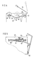
- the saw table 1 has a table top 2 with all-round guide and fastening strips 3 with preferably T-shaped grooves 4 (see also FIG. 5) for attaching stops 5.
- the table top 2 has an elongated slot 6 in its central region, which is located in the plane of a saw blade 7 which can be moved therein and which belongs to a saw unit 8 shown in FIG. For sawing, the saw blade 7 is moved in the feed direction indicated by an arrow.
- the table top 2 is connected to a housing 9 which has removable feet 10.
- swivel lever 13 consisting of two parallel pieces of pipe, which has at its free-standing end a handle 14 which is transverse to the pieces of pipe and connects them.
- the effective length L of the lever 13 from the handle 14 to its pivot point is preferably approximately 500-800 mm.
- the saw unit 8 shown in FIG. 2 is a commercially available hand-held circular saw with a base plate 15.
- the base plate 15 is mounted on a slide 17, for example with screws 16.
- the carriage 17 has rollers 18 which run in guides 19 of the table top 2.
- the carriage 17 can also be pivotally attached to the saw table 1 in order to bring the saw blade 7 into different angular positions with respect to the table top 2 for miter cuts.
- the guides 19 have a circular cross section in the regions that come into contact with the rollers 18, so that the rollers 18 engage behind the guides 19 with their adapted cup-shaped cross section. A horizontal and vertical fixing of the slide 17 with respect to the saw table 2 thus takes place immediately.
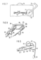
- a bevel gear 21 is shown as a gear 20 for translating the pivoting movement of the lever 13 into the linear movement of the saw unit 8.
- the pivot lever 13, which in this case preferably penetrates the rear wall 11 of the housing 9, is connected to a bevel gear 22.
- This bevel gear meshes with a bevel gear 23 arranged at right angles thereto.
- a roller 24 is seated on the shaft of the bevel gear 23, if appropriate at a suitable distance Saw unit 8 or the carriage 17 is attached.
- the pivot lever 13 is plugged into a pipe section 27 so that it can be removed for transport. It can also be removed if the saw table is used as a conventional circular saw table with a fixed saw blade. In this case, the carriage 17 is locked and the workpiece is moved towards the saw blade in the usual manner during sawing.
- the cable can also be run over vertical rollers.
- a spur gear is used instead of the bevel gear.
- a ring gear can be used to reverse the direction of displacement of the motor.
- Planetary gears can also be used advantageously.
- a toothed belt or a chain (bicycle chain) can also be used.
- the ends of the rope or belt can also be wound a few turns around the deflection rollers, similar to a car window crank.
- the rope can also be guided over pulleys or guides e.g. like a Bowden cable.
- a return spring can be attached to the hand levers or the cable pulls according to the exemplary embodiments in FIGS. 1 and 2, which returns the saw blade to the starting position before sawing for safety reasons.
- a workpiece is placed on the table top, if necessary at the stop 5.
- the saw blade is initially in its rear position closest to lever 13. After the saw unit has been switched on, the lever 13 is pulled down in the direction of the arrow toward the operator standing in front of the saw table 1 until the handle 14 is approximately 200 mm from the table top 2 in its end position. The saw blade moves in the feed direction towards the operator along the slot 6.
- the lever movement is translated into a linear movement by means of a sliding crank mechanism 30.
- the hand lever 31 is fastened to a toothed or friction wheel 32 which drives the toothed or friction wheel 33, which is connected to the lever 34 of the slider crank mechanism.
- the rod 35 is connected via joints 36 and 37 to the guide carriage 38 of the circular saw.
- the position of the hand lever 31 and the gear 30 before the saw cut is shown in dashed lines.
- the thrust crank mechanism 30 is advantageously designed such that the dead centers do not fall into the driving range of the guide carriage.
- a rotatably mounted spindle 40 has two areas 41 and 42 with possibly different pitches and / or different pitch directions, in each of which a nut 43 or 44 engages.
- the saw unit 45 is fastened to the nut 43 with the saw blade 46.
- the spindle 40 can simultaneously serve as a linear guide for the saw unit 45.
- the protective hood of the saw unit has a connecting piece 47 for a suction hose.
- the feed lever 49 is attached to the second nut 44 via a rod 48.
- a return spring 50 in the swivel joint of the feed lever ensures that the saw unit moves back automatically into the starting position shown in FIG.
- the spindle 40 alternatively has a hand crank 51 at its front end; An electric servomotor can also replace the hand crank.
- the spindle can be locked by means of a lever 52 with a locking member 53 to fix the saw unit during transport or during table saw operation.
- the spindle gear (40, 43, 44) is inserted into a saw table 54 with a table top 55, which in turn has fastening strips 56 on the outer edge.
- the spindle 40 By moving the feed lever 49, the spindle 40 is rotated by the nut 44. The rotation of the spindle produces a linear movement of the saw unit 45 in the second nut 43.
- a gear ratio can be achieved by varying the thread pitch in the areas 41 and 42. For the threads, pitches between 30 ° and 50 ° are advantageous. If necessary, the threads can be multi-start.
- the nuts can be slide nuts or nuts with rolling elements, for example also ball nuts or part of a ball screw. In the simplest case offers a deep groove ball bearing without an inner ring and correspondingly rolled multi-start ball tracks on the spindle.
- the spindle drive can also serve as a guideway for the saw unit.
- the return spring 50 can be designed as a torsion spring with a round or rectangular cross section. Alternatively, a roller spring can also be attached, for example, directly to the saw unit 45.
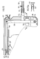
- the spindle 60 is mounted in a rotationally rigid manner.
- a sleeve 61 with an internal and external thread is pushed over the thread of the spindle 60 by means of the pivot lever 62.
- the pivot lever 62 is articulated on a ring 63 which is rotatably but axially fixedly connected to the sleeve 61.
- the sleeve 61 rotates on its external thread with respect to the non-rotatable spindle 60 and a nut 64 which is non-rotatable with respect to the sag table 67.
- the saw unit (not shown) is attached to the outside of the nut 64.
- the desired route can be set by selecting the appropriate slope.
- the pivot lever 62 is articulated in a swivel joint 65 on the rear wall 66 of the saw table 67.
- the sleeve 61 moves on the spindle 60 from right to left or vice versa; at the same time the nut 64 moves away from the ring 63 of the sleeve 61 to the left or vice versa. This results in the desired extension of the travel path of the saw unit compared to the short lever travel.
- the rotatably mounted spindle 70 is provided with a bevel gear 71 which meshes with the bevel gear 72 of the hand lever 73.
- the saw unit not shown, is fastened to the saw blade 75 on the nut 74 which does not rotate.
- the hand lever can be replaced or supplemented by a servomotor in a simple manner.
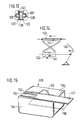
- FIG. 8 shows a sixth exemplary embodiment of a spherical flat guide 79, which consists of an upper guide rail 80, a lower guide rail 81 and a ball cage 82.
- Balls 84 are held in the openings 83 of the ball cage 82.
- the ball cage 82 has fastening tabs 85.
- the balls 84 roll in the curved tracks 86 and 87 of the guide rails.
- the raceways are so braced against each other that a forced unrolling takes place in such a way that when the lower guide rail 81 is held, the upper guide rail 80 moves in the longitudinal direction with respect to the ball cage 82 at twice the speed.
- the saw unit 90 with the saw blade 91 is firmly connected to the upper guide rail 80, which thus serves as a displaceable slide 80.
- the lower guide rail 81 is firmly connected to the housing of the underfloor saw 1.
- a rod 92, which is articulated on the feed lever 93, is fastened to the fastening tab 85 of the ball cage 82.
- the feed lever 93 is rotatable in the usual way in a joint 94 connected to the housing of the saw.
- the balls which are positively guided via frictional engagement, have the effect that when the cage 82 is driven, the second guideway 80 is displaced twice as far as the held guideway 81 than the cage 82 itself.
- the desired translation of the lever path into the linear movement of the saw unit 90 is thus achieved.
- the frictional forces of the balls can be designed, for example, at 100 N feed force. This means that sawing work can be carried out perfectly.
- slipping of the balls can be achieved, for example to put the pivoting lever position in an ergonomically favorable position for a certain sawing work.
- the flat guide also expediently serves as an aggregate linear guide.
- the integration of feed force introduction and linear guide is not only inexpensive, but it can also be attached particularly close to the saw blade. This has static advantages, because the ideal area for guiding and feeding force is in the saw blade level.
- FIGS. 10 and 11 show a further variant of a ball guide as the seventh exemplary embodiment.
- a carriage 100, on which the saw unit 101 is fastened, is displaceably mounted on the one hand in a slider 102, which is fastened to the table top 103 of a saw table 108.
- the other side of the carriage 100 has a guide tube 104.
- the guide rod 107 is firmly connected to the saw table 108.
- the cage 105 carries at its end a ring 109 on which the pivot lever 110 is articulated by means of a rod 111.
- the rod 111 passes through a slot 112 on the rear wall 113 of the saw table 108.
- the pivot lever 110 is also articulated in a swivel joint 114 on the rear wall 113.
- a bellows 115 is attached between the ring 109 and the guide tube 104.
- this ball guide 108 corresponds to that of the two previous exemplary embodiments.
- the guide tube 104 with the carriage 100 attached to it moves by the distance 2X.
- the balls can also be replaced by gear wheels 120 which run in racks 121 and 122 of two guide rails 123 and 124.
- the guide rail 124 is fixedly connected to the saw table 127, while a slide 125 is attached to the sliding guide rail 123 with a saw unit.
- a pivoting angle of the feed lever 128 of 30 °, there is a displacement path of the saw unit of 345 mm.
- the feed lever consists of a pipe section 128 with a handle (not shown) and a rod 129 to which a short pipe section 131 is welded, into which the pipe section 128 can be inserted and locked.
- the spring-loaded locking pin 132 which can be unlocked by pressing the button 133, serves this purpose.
- the rod 129 is mounted in a swivel joint 134 which is connected to the housing of the saw table 127 and is fastened to the rear wall 135 of the saw table 127 within the housing. In its position closest to the housing (as shown in FIG. 12), the rod 129 can be locked by means of a band spring 136 which surrounds it resiliently. In this position, the saw unit is fixed in place, so that the saw table 127 serves as a conventional circular saw table.
- a hydraulic transmission is used in the ninth embodiment.
- the hand lever 140 is connected to the piston 141 of the hydraulic cylinder 142.
- the two piston chambers of the cylinder 142 are optionally connected crosswise to the piston chambers of the hydraulic cylinder 143.
- the saw unit is connected to the piston 144 of this cylinder.
- a feed movement of the hand lever 140 at the same time causes a feed movement of the saw unit that is translated into faster because of the different piston dimensions.
- the direction of travel can be determined in a simple manner by appropriate selection of the line routing between the cylinders 142 and 143.
- the travel ratio can also be influenced according to the respective requirements by the choice of the piston diameter.
- FIG. 15 shows a portable underfloor saw table 149 which can also be used as a sliding table saw.
- the saw blade 150 is advantageously fixed stationary in any position in this use. However, as with the other exemplary embodiments, it can also be moved, preferably with a fixed table, by means of a lever (not shown).
- a part 151 of the table top can be moved longitudinally in the cutting direction of the saw blade.
- the displaceable table half 151 is no longer than the fixed table top 156 and does not protrude beyond the housing 154. This makes it easier to tidy up and transport the saw table and serves to ensure safety against accidents.
- a workpiece is placed on the table top part 151 and moved together with the latter to the saw blade 150.
- the embodiment according to FIG. 15 enables both pulling cross-cut saws and fully-fledged format saws with a handy, sliding table that does not interfere with work. If necessary, both working methods can also be combined.
- the invention is not limited to the specific exemplary embodiments.
- the individual exemplary embodiments can be combined with others, in particular the gears can be exchanged.
- the function of the second and the following exemplary embodiments corresponds to that of the first example.
Description
Die Erfindung geht aus von einem Sägetisch nach der Gattung des spruchs 1. Solche Sägetische ermöglichen ähnlich einer Kappsäge das Sägen von festeingespannten Werkstücken. Gemäß dem DE-GM 81 16 406 ist ein solcher Sägetisch mit festeingespanntem Sägeaggregat bekannt, bei dem die Übersetzung der Schwenkbewegung des Handhebels in die geradlinige Bewegung des Sägeblattes mittels eines am Ende des Hebels befestigten Seilzuges bewirkt wird. Dabei hängt die Länge des Verschiebeweges des Sägeaggregats direkt von der Länge des Hebels ab. Bei der im Ausführungsbeispiel angegebenen Tischhöhe von 260 mm ergibt sich damit ein Verschiebeweg von nur etwa 150 mm, wenn der Schwenkwinkel des Handhebels innerhalb des ergonomisch noch vertretbaren Bereichs von unter 40° verbleiben soll. Eine Verlängerung des Verschiebewegs auf 25 cm führt nach dem Stand der Technik zu einem Schwenkwinkel von ca. 67°, der den ergonomisch günstigen Bewegungsbereich des Armes der Bedienungsperson von ca. 30° - 40° bei weitem überschreitet.The invention is based on a saw table according to the type of claim 1. Such saw tables enable the sawing of firmly clamped workpieces, similar to a cross-cut saw. According to DE-GM 81 16 406, such a saw table with a firmly clamped saw unit is known in which the translation of the pivoting movement of the hand lever into the linear movement of the saw blade is effected by means of a cable pull attached to the end of the lever. The length of the displacement of the saw unit depends directly on the length of the lever. With the table height of 260 mm specified in the exemplary embodiment, this results in a displacement path of only approximately 150 mm if the pivoting angle of the hand lever is to remain within the ergonomically still acceptable range of less than 40 °. According to the prior art, an extension of the displacement path to 25 cm leads to a swivel angle of approx. 67 °, which far exceeds the ergonomically favorable range of movement of the operator's arm of approx. 30 ° - 40 °.
Dem erfindungsgemäßen Sägetisch mit den kennzeichnenden Merkmalen der Unabhängigen Ansprüche liegt die Aufgabe Zugrunde, eine ergonomisch sinnvolle Länge des Bedienungshebels und ein ergonomisch sinnvolles Übersetzungsverhältnis des Getriebes unter Einhaltung der Werkzeugtischhöhe zu erreichen. Dabei kann das Sägeblatt sowohl vorwärts als auch rückwärts geführt werden.The task of the saw table according to the invention with the characterizing features of the independent claims is to achieve an ergonomically sensible length of the operating lever and an ergonomically sensible transmission ratio of the gear unit while observing the tool table height. The saw blade can be guided both forwards and backwards.
Durch die in den Ansprüchen 2 ff aufgeführten Maßnahmen sind vorteilhafte Weiterbildungen und Verbesserungen des im Anspruch 1 angegebenen Sägetisches möglich. Die Ansprüche 2 bis 8 betreffen verschiedene Ausbildungen des Übersetzungsgetriebes; eine Doppelspindel mit verschiedenen Steigungen erlaubt eine günstige Übersetzung. Bei der Verwendung einer Kugelumlaufspindel verringert sich die Reibung erheblich. Ein Spindeltrieb, oder eine Kugel- oder Rollenführung gewährleisten gleichzeitig eine Geradführung des Schlittens für das Sägeblatt bzw. den Motor. Bei der Kugel- oder Rollenführung kann der Schwenkbereich des Hebels leicht justiert werden. Die Verwendung von Hydraulikzylindern hat den zusätzlichen Vorteil, daß in den Endlagen des Verschiebewegs der Rücklaufstoß gedämpft wird. Die geschwindigkeitsproportionale Dämpfung ist auch während des Sägens beim Verklemmen des Sägeblatts vorteilhaft und sicherer.Advantageous further developments and improvements of the saw table specified in claim 1 are possible through the measures listed in claims 2 ff. Claims 2 to 8 relate to different designs of the transmission gear; a double spindle with different pitches allows a favorable translation. When using a ball screw, the friction is significantly reduced. A spindle drive, or a ball or roller guide simultaneously ensure that the carriage is guided straight for the saw blade or the motor. With the ball or roller guide, the swivel range of the lever can be easily adjusted. The use of hydraulic cylinders has the additional advantage that the return stroke is damped in the end positions of the displacement path. The speed-proportional damping is also advantageous and safer when sawing when the saw blade is jammed.
Gemäß Anspruch 10 kann der Handhebel auch durch einen elektrischen Stellmotor ersetzt werden. Besonders vorteilhaft ist es gemäß Anspruch 11, den Schwenkhebel bzw. Vorschubhebel an der Rückwand des Sägetisches anzuordnen. Damit bleibt er außerhalb des Auflagebereichs von zu sägenden Werkstücken und ermöglicht die Anbringung von Führungs- und Befestigungsleisten am Sägetisch an allen vier Seiten. Die Ansprüche 14 bis 17 beschreiben ergonomisch besonders günstige Ausführungen des Hebels. Insbesondere hat der mit seiner Achse quer zur Schwenkrichtung verlaufende Handgriff den Vorteil, daß die Bedienungsperson während der Bedienung des Hebels nicht umgreifen muß.According to
10 Ausführungsbeispiele der Erfindung sind in der Zeichnung dargestellt und in der nachfolgenden Beschreibung näher erläutert.
- Figur 1 zeigt ein erstes Ausführungsbeispiel in Ansicht,
- Figur 2 zeigt einen Schnitt durch den Sägetisch des ersten Ausführungsbeispiels und
Figur 3 zeigt das Getriebe des ersten Ausführungsbeispiels.- Figur 4 zeigt ein Getriebe nach einem zweiten Ausführungsbeispiel,
Figur 5 zeigt einen Querschnitt durch das dritte Ausführungsbeispiel,- Figur 6 zeigt das Getriebe eines vierten Ausführungsbeispiels und
- Figur 7 zeigt das Getriebe eines fünften Ausführungsbeispiels.
- Figur 8 zeigt eine teilweise aufgeschnittene perspektivische Ansicht eines sechsten Ausführungsbeispiels und
- Figur 9 zeigt eine Ansicht des sechsten Ausführungsbeispiels.
Figur 10 zeigt einen Querschnitt durch das siebte Ausführungsbeispiel undFigur 11 zeigt einen Schnitt durch das Getriebe nach dem siebten Ausführungsbeispiel.- Figur 12 zeigt einen Querschnitt eines achten Ausführungsbeispiels und
Figur 13 eine Variante des Zahnrades des achten Ausführungsbeispiels.Figur 14 zeigt eine Prinzipskizze eines neunten Ausführungsbeispiels undFigur 15 die Ansicht eines zehnten Ausführungsbeispiels.
- FIG. 1 shows a first exemplary embodiment in view,
- Figure 2 shows a section through the saw table of the first embodiment and
- Figure 3 shows the transmission of the first embodiment.
- FIG. 4 shows a transmission according to a second exemplary embodiment,
- FIG. 5 shows a cross section through the third exemplary embodiment,
- Figure 6 shows the transmission of a fourth embodiment and
- Figure 7 shows the transmission of a fifth embodiment.
- FIG. 8 shows a partially cutaway perspective view of a sixth exemplary embodiment and
- Figure 9 shows a view of the sixth embodiment.
- Figure 10 shows a cross section through the seventh embodiment and
- Figure 11 shows a section through the transmission according to the seventh embodiment.
- Figure 12 shows a cross section of an eighth embodiment and
- Figure 13 shows a variant of the gear of the eighth embodiment.
- Figure 14 shows a schematic diagram of a ninth embodiment and
- Figure 15 is a view of a tenth embodiment.
Der Sägetisch 1 weist eine Tischplatte 2 mit ringsum umlaufenden Führungs- und Befestigungsleisten 3 mit vorzugsweise T-förmigen Nuten 4 (siehe auch Figur 5) zum Anbringen von Anschlägen 5 auf. Die Tischplatte 2 weist in ihrem Mittelbereich einen langgestreckten Schlitz 6 auf, der sich in der Ebene eines darin verschieblichen Sägeblattes 7, das zu einem in Figur 2 gezeigten Sägeaggregat 8 gehört, befindet. Zum Sägen wird das Sägeblatt 7 in der mit einem Pfeil bezeichneten Vorschubrichtung bewegt. Die Tischplatte 2 ist mit einem Gehäuse 9 verbunden, das abnehmbare Aufstellfüße 10 aufweist.The saw table 1 has a table top 2 with all-round guide and
An der der Vorschubrichtung abgewandten Rückwand 11 des Gehäuses 9 sind Schlitze 12 angeordnet. Durch diese greift ein aus zwei parallelen Rohrstücken bestehender Schwenkhebel 13, der an seinem freistehenden Ende einen quer zu den Rohrstücken stehenden und diese verbindenden Handgriff 14 aufweist. Die wirksame Länge L des Hebels 13 vom Handgriff 14 bis zu seinem Drehpunkt beträgt vorzugsweise ca. 500 - 800 mm.Slots 12 are arranged on the
Das in Figur 2 gezeigte Sägeaggregat 8 ist eine handelsübliche Handkreissäge mit Fußplatte 15. Die Fußplatte 15 ist beispielsweise mit Schrauben 16 auf einen Schlitten 17 montiert. Der Schlitten 17 weist Rollen 18 auf, die in Führungen 19 der Tischplatte 2 laufen. Der Schlitten 17 kann auch schwenkbar an dem Sägetisch 1 befestigt sein, um das Sägeblatt 7 für Gehrungsschnitte in verschiedene Winkelstellungen zur Tischplatte 2 zu bringen. Im Ausführungsbeispiel haben die Führungen 19 in dem mit den Rollen 18 in Kontakt kommenden Bereichen kreisförmigen Querschnitt, so daß die Rollen 18 mit ihrem angepaßten schalenförmigen Querschnitt die Führungen 19 hintergreifen. Damit erfolgt sogleich eine horizontale wie vertikale Festlegung des Schlittens 17 gegenüber dem Sägetisch 2.The saw unit 8 shown in FIG. 2 is a commercially available hand-held circular saw with a
In Figur 3 ist als Getriebe 20 zur Übersetzung der Schwenkbewegung des Hebels 13 in die lineare Bewegung des Sägeaggregats 8 ein Kegelradgetriebe 21 gezeigt. Der Schwenkhebel 13, der in diesem Fall vorzugsweise die Rückwand 11 des Gehäuses 9 durchdringt, ist mit einem Kegelrad 22 verbunden. Dieses Kegelrad kämmt mit einem rechtwinklig dazu angeordneten Kegelrad 23. Auf der Welle des Kegelrades 23 sitzt ggf. in passendem Abstand eine Rolle 24. Über diese Rolle 24 und eine in Vorschubrichtung des Sägeaggregats entfernt angeordnete Rolle 25 ist ein Seilzug 26 gespannt, an dem das Sägeaggregat 8 bzw. der Schlitten 17 befestigt ist.In Figure 3, a bevel gear 21 is shown as a
Der Schwenkhebel 13 ist steckbar in einem Rohrstück 27 befestigt, so daß er zum Transport herausgenommen werden kann. Er kann ebenfalls herausgenommen werden, wenn der Sägetisch als herkömmlicher Kreissägentisch mit feststehendem Sägeblatt verwendet wird. In diesem Fall wird der Schlitten 17 arretiert und beim Sägen in gewohnter Weise das Werkstück auf das Sägeblatt zubewegt.The
Der Seilzug kann auch über senkrecht stehende Rollen geführt werden. Dabei wird ein Stirnradgetriebe statt des Kegelradgetriebes verwendet. Um eine Richtungsumkehr der Verschiebebewegung des Motors zu erreichen, kann ein Hohlrad verwendet werden. Auch Planetengetriebe können vorteilhaft eingesetzt werden. Statt eines Seils kann auch ein Zahnriemen oder eine Kette (Fahrradkette) eingesetzt werden. Um ein Durchrutschen des Seils oder Riemens zu verhindern, können die Seil- oder Riemenenden auch ähnlich einer Autofensterkurbel einige Windungen um die Umlenkrollen aufgewickelt werden. Gegebenenfalls kann das Seil auch über Umlenkrollen oder Führungen z.B. wie bei einem Bowdenzug geführt werden. Aus Gründen der Arbeitssicherheit kann an den Handhebeln oder den Seilzügen nach den Ausführungsbeispielen der Figuren 1 und 2 eine Rückholfeder angebracht sein, die das Sägeblatt aus Sicherheitsgründen in die Ausgangsstellung vor dem Sägen zurückführt.The cable can also be run over vertical rollers. A spur gear is used instead of the bevel gear. A ring gear can be used to reverse the direction of displacement of the motor. Planetary gears can also be used advantageously. Instead of a rope, a toothed belt or a chain (bicycle chain) can also be used. In order to prevent the rope or belt from slipping, the ends of the rope or belt can also be wound a few turns around the deflection rollers, similar to a car window crank. If necessary, the rope can also be guided over pulleys or guides e.g. like a Bowden cable. For reasons of occupational safety, a return spring can be attached to the hand levers or the cable pulls according to the exemplary embodiments in FIGS. 1 and 2, which returns the saw blade to the starting position before sawing for safety reasons.
Zum Sägen wird ein Werkstück auf die Tischplatte, gegebenenfalls an den Anschlag 5 gelegt. Das Sägeblatt befindet sich zu Anfang in seiner dem Hebel 13 nächstgelegenen hinteren Stellung. Nach Einschalten des Sägeaggregats wird der Hebel 13 auf die vor dem Sägetisch 1 stehende Bedienungsperson hin in Pfeilrichtung heruntergezogen bis in seiner Endstellung der Handgriff 14 sich ca. 200 mm von der Tischplatte 2 entfernt befindet. Dabei bewegt sich das Sägeblatt in Vorschubrichtung auf die Bedienungsperson zu entlang dem Schlitz 6.For sawing, a workpiece is placed on the table top, if necessary at the
Gemäß dem zweiten Ausführungsbeispiel nach Figur 4 wird die Hebelbewegung mittels eines Schubkurbelgetriebes 30 in eine Linearbewegung übersetzt. Der Handhebel 31 ist an einem Zahn- oder Reibrad 32 befestigt, der das Zahn- oder Reibrad 33 antreibt, das mit dem Hebel 34 des Schubkurbelgetriebes verbunden ist. Die Stange 35 ist über Gelenke 36 und 37 mit dem Führungsschlitten 38 der Kreissäge verbunden. Die Stellung des Handhebels 31 und des Getriebes 30 vor dem Sägeschnitt ist gestrichelt dargestellt. Das Schubkurbelgetriebe 30 ist vorteilhaft so ausgelegt, daß die Totpunkte nicht in den Fahrbereich des Führungsschlittens fallen.According to the second exemplary embodiment according to FIG. 4, the lever movement is translated into a linear movement by means of a sliding
Nach dem dritten Ausführungsbeispiel in Figur 5 weist eine drehbar gelagerte Spindel 40 zwei Bereiche 41 und 42 mit gegebenenfalls unterschiedlicher Steigung und/oder unterschiedlicher Steigungsrichtung auf, in die jeweils eine Mutter 43 bzw. 44 eingreift. An der Mutter 43 ist das Sägeaggregat 45 mit dem Sägeblatt 46 befestigt. Die Spindel 40 kann gleichzeitig als Linear-Führung für das Sägeaggregat 45 dienen. Die Schutzhaube des Sägeaggregats weist einen Anschlußstutzen 47 für einen Absaugschlauch auf. An der zweiten Mutter 44 ist über eine Stange 48 der Vorschubhebel 49 angebracht. Eine Rückholfeder 50 im Drehgelenk des Vorschubhebels sorgt für ein selbständiges Zurückfahren des Sägeaggregats in die in der Figur 5 dargestellte Ausgangsposition. Die Spindel 40 weist an ihrem vorderen Ende alternativ eine Handkurbel 51 auf; an die Stelle der Handkurbel kann auch ein elektrischer Stellmotor treten. Über einen Hebel 52 mit Riegelglied 53 läßt sich die Spindel zur Festlegung des Sägeaggregats beim Transport oder beim Tischsägenbetrieb arretieren.According to the third exemplary embodiment in FIG. 5, a rotatably mounted
Das Spindelgetriebe (40, 43, 44) ist in einen Sägetisch 54 mit einer Tischplatte 55 eingesetzt, die wiederum am Außenrand Befestigungsleisten 56 aufweist.The spindle gear (40, 43, 44) is inserted into a saw table 54 with a
Durch eine Bewegung des Vorschubhebels 49 wird die Spindel 40 durch die Mutter 44 in Drehung versetzt. Die Spindelumdrehung erzeugt in der zweiten Mutter 43 eine Linearbewegung des Sägeaggregats 45. Durch unterschiedliche Steigung der Gewinde in den Bereichen 41 und 42 kann eine Getriebeübersetzung erfolgen. Für die Gewinde sind Steigungen zwischen 30° und 50° vorteilhaft. Die Gewinde können gegebenenfalls mehrgängig ausgeführt werden. Die Muttern können Gleitmuttern oder Muttern mit Wälzkörpern sein, z.B. auch Kugelumlaufmuttern bzw. Teil einer Kugelumlaufspindel. Im einfachsten Falle bietet sich ein Rillenkugellager ohne Innenring und entsprechend gewalzte mehrgängige Kugelbahnen auf der Spindel an. Der Spindeltrieb kann gleichzeitig auch als Führungsbahn für das Sägeaggregat dienen. Die Rückholfeder 50 kann als Drehfeder mit rundem oder rechteckigem Querschnitt ausgebildet sein. Alternativ kann auch eine Rollfeder beispielsweise direkt am Sägeaggregat 45 befestigt sein.By moving the
Nach dem vierten Ausführungsbeispiel in Figur 6 ist die Spindel 60 drehstarr gelagert. Über das Gewinde der Spindel 60 wird eine Hülse 61 mit Innen- und Außengewinde mittels des Schwenkhebels 62 geschoben. Der Schwenkhebel 62 ist an einem mit der Hülse 61 drehbar aber axial fest verbundenen Ring 63 angelenkt. Die Hülse 61 dreht sich beim Schwenken des Hebels 62 gegenüber der drehfesten Spindel 60 und einer gegenüber dem Sagetisch 67 drehfesten Mutter 64 auf ihrem Außengewinde. Außen an der Mutter 64 ist das nicht gezeigte Sägeaggregat befestigt. Durch entsprechende Steigungswahl kann der gewünschte Fahrweg eingestellt werden. Der Schwenkhebel 62 ist in einem Drehgelenk 65 an der Rückwand 66 des Sägetisches 67 angelenkt.According to the fourth exemplary embodiment in FIG. 6, the
Bei Betätigung des Handhebels 62 wandert die Hülse 61 auf der Spindel 60 von rechts nach links bzw. umgekehrt; gleichzeitig wandert die Mutter 64 vom Ring 63 der Hülse 61 weg nach links bzw. umgekehrt. Dadurch ergibt sich die gegenüber dem kurzen Hebelweg gewünschte Verlängerung des Fahrwegs des Sägeaggregats.When the
In Figur 7 ist die drehbar gelagerte Spindel 70 mit einem Kegelrad 71 versehen, die mit dem Kegelrad 72 des Handhebels 73 kämmt. An der nicht mitdrehenden Mutter 74 ist das nicht gezeigte Sägeaggregat mit dem Sägeblatt 75 befestigt. Bei allen Spindelgetrieben läßt sich in einfacher Weise der Handhebel durch einen Stellmotor ersetzen bzw. ergänzen.In Figure 7, the rotatably mounted
In Figur 8 ist als sechstes Ausführungsbeispiel eine Kugelflachführung 79 gezeigt, die aus einer oberen Führungsschiene 80, einer unteren Führungsschiene 81 und einem Kugelkäfig 82 besteht. In den Durchbrechungen 83 des Kugelkäfigs 82 sind Kugeln 84 gehalten. Der Kugelkäfig 82 weist Befestigungslaschen 85 auf. Die Kugeln 84 rollen in den gewölbten Laufbahnen 86 und 87 der Führungsschienen ab. Die Laufbahnen sind dabei so gegeneinander verspannt, daß eine Zwangsabrollung in der Weise erfolgt, daß sich bei festgehaltener unterer Führungsschiene 81 die obere Führungsschiene 80 gegenüber dem Kugelkäfig 82 mit der doppelten Geschwindigkeit in Längsrichtung bewegt.8 shows a sixth exemplary embodiment of a spherical
Dieser Sachverhalt wird ausgenutzt zum Antrieb des Sägeaggregats 90 gemäß der Ausführung nach Figur 9. Das Sägeaggregat 90 mit Sägeblatt 91 ist fest mit der oberen Führungsschiene 80 verbunden, die damit als verschiebbarer Schlitten 80 dient. Die untere Führungsschiene 81 ist fest mit dem Gehäuse der Unterflursäge 1 verbunden. An der Befestigungslasche 85 des Kugelkäfigs 82 ist eine Stange 92 befestigt, die an dem Vorschubhebel 93 angelenkt ist. Der Vorschubhebel 93 ist in üblicher Weise drehbar in einem mit dem Gehäuse der Säge verbundenen Gelenk 94.This fact is used to drive the
Die über Reibschluß zwangsgeführten Kugeln bewirken, daß beim Antrieb des Käfigs 82 sich die zweite Führungsbahn 80 gegenüber der festgehaltenen Führungsbahn 81 um den doppelten Weg verschiebt als der Käfig 82 selbst. Damit wird die gewünschte Übersetzung des Hebelwegs in die Linearbewegung des Sägeaggregats 90 erreicht. Die Reibschlußkräfte der Kugeln lassen sich z.B. auf 100 N Vorschubkraft auslegen. Damit lassen sich Sägearbeiten einwandfrei durchführen. Andererseits ist in den Endlagen der Flachführung ein Durchrutschen der Kugeln erzielbar, um etwa die Schwenkhebelposition für eine bestimmte Sägearbeit in eine ergonomisch günstige Lage zu versetzen.The balls, which are positively guided via frictional engagement, have the effect that when the
Die Flachführung dient zweckmäßigerweise auch als Aggregatlinearführung. Die Integration von Vorschubkrafteinleitung und Linearführung ist nicht nur kostengünstig, sondern sie läßt sich auch besonders nahe beim Sägeblatt anbringen. Dies hat statische Vorteile, denn der ideale Bereich für Führung und Vorschubkrafteinleitung liegt in der Sägeblattebene.The flat guide also expediently serves as an aggregate linear guide. The integration of feed force introduction and linear guide is not only inexpensive, but it can also be attached particularly close to the saw blade. This has static advantages, because the ideal area for guiding and feeding force is in the saw blade level.
In den Figuren 10 und 11 ist als siebtes Ausführungsbeispiel eine weitere Variante einer Kugelführung gezeigt. Ein Schlitten 100, an dem das Sägeaggregat 101 befestigt ist, ist einerseits in einem Gleitstück 102 verschieblich gelagert, das an der Tischplatte 103 eines Sägetisches 108 befestigt ist. Die andere Seite des Schlittens 100 weist ein Führungsrohr 104 auf. Darin befinden sich von einem Käfig 105 gehaltene Kugeln 106, die sich nach innen gegen eine Führungsstange 107 abstützen. Die Führungsstange 107 ist fest mit dem Sägetisch 108 verbunden.FIGS. 10 and 11 show a further variant of a ball guide as the seventh exemplary embodiment. A
In Figur 11 ist gezeigt, daß der Käfig 105 an seinem Ende einen Ring 109 trägt, an dem der Schwenkhebel 110 mittels einer Stange 111 angelenkt ist. Die Stange 111 durchgreift einen Schlitz 112 an der Rückwand 113 des Sägetisches 108. Der Schwenkhebel 110 ist wie in den vorherigen Ausführungsbeispielen außerdem noch in einem Drehgelenk 114 an der Rückwand 113 angelenkt. Um Käfig 105 und Kugeln 106 zu schützen, ist zwischen dem Ring 109 und dem Führungsrohr 104 ein Faltenbalg 115 angebracht.In FIG. 11 it is shown that the
Die Funktion dieser Kugelführung 108 entspricht der der beiden vorherigen Ausführungsbeispiele. Beim Verschieben des Ringes 109 durch den Hebel 110 um die Strecke X bewegt sich das Führungsrohr 104 mit dem daran befestigten Schlitten 100 um die Strecke 2X.The function of this ball guide 108 corresponds to that of the two previous exemplary embodiments. When the
Gemäß dem achten Ausführungsbeispiel nach Figur 12 und 13 können die Kugeln auch durch Zahnräder 120 ersetzt werden, die in Zahnstangen 121 und 122 zweier Führungsschienen 123 und 124 laufen. Die Führungsschiene 124 ist fest mit dem Sägetisch 127 verbunden, während an der schiebbaren Führungsschiene 123 ein Schlitten 125 mit einem Sägeaggregat befestigt ist. Eine derartige Zahnradführung läßt sich genauso wie die vorher beschriebene Kugelflachführung in der Unterflursäge verwenden, wenn der Vorschubhebel 128, 129 über eine Schubstange 130 an der Achse 126 des Zahnrads 120 angreift. In diesem Fall ergibt sich wiederum ein Übersetzungsverhältnis von i = 2. Bei diesem Ausführungsbeispiel ergibt sich bei einem Schwenkwinkel des Vorschubhebels 128 von 30° ein Verschiebeweg des Sägeaggregats von 345 mm.According to the eighth exemplary embodiment according to FIGS. 12 and 13, the balls can also be replaced by
Der Vorschubhebel besteht aus einem Rohrstück 128 mit nicht gezeigtem Handgriff und einem Stab 129 an den ein kurzes Rohrstück 131 angeschweißt ist, in das das Rohrstück 128 einschiebbar und arretierbar ist. Dazu dient der federbelastete Raststift 132, der durch Druck auf den Knopf 133 entriegelbar ist. Der Stab 129 ist in einem mit dem Gehäuse des Sägetisches 127 verbundenen Drehgelenk 134 gelagert, das an der Rückwand 135 des Sägetisches 127 innerhalb des Gehäuses befestigt ist. In seiner gehäusenächsten Stellung (wie in Figur 12 gezeigt) ist der Stab 129 mittels einer diesen federnd umschließenden Bandfeder 136 arretierbar. In dieser Position ist das Sägeaggregat ortsfest fixiert, so daß der Sägetisch 127 als herkömmlicher Kreissägetisch dient.The feed lever consists of a
Andere Übersetzungsverhältnisse als i = 2 sind erzielbar, wenn gemäß Figur 13 auf die Achse 126 ein oder zwei weitere Zahnräder 137 mit gegenüber dem Zahnrad 120 geringerem (oder größerem) Wälzkreis aufgesetzt sind und mit seiner Verzahnung in eine dem Walzradius der Zahnräder 137 angepaßte Führungsschiene 124' eingreift.Gear ratios other than i = 2 can be achieved if, according to FIG. 13, one or two further gearwheels 137 with a smaller (or larger) pitch circle than
Gemäß Figur 14 kommt im neunten Ausführungsbeispiel ein hydraulisches Getriebe zum Einsatz. Der Handhebel 140 ist mit dem Kolben 141 des Hydraulikzylinders 142 verbunden. Die beiden Kolbenräume des Zylinders 142 sind gegebenenfalls über Kreuz mit den Kolbenräumen des Hydraulikzylinders 143 verbunden. Mit dem Kolben 144 dieses Zylinders wird das Sägeaggregat verbunden. Somit bewirkt eine Vorschubbewegung des Handhebels 140 gleichzeitig eine wegen der unterschiedlichen Kolbenabmessungen ins schnellere übersetzte Vorschubbewegung des Sägeaggregats. Durch entsprechende Wahl der Leitungsführung zwischen den Zylindern 142 und 143 kann auf einfache Weise die Fahrwegrichtung bestimmt werden. Auch die Wegübersetzung kann entsprechend den jeweiligen Erfordernissen durch Wahl der Kolbendurchmesser beeinflußt werden. Durch die Verschaltung der beiden Zylinder ist sowohl eine Vorschub- als auch eine Rückschubbewegung des Sägeaggregats möglich. In den Endlagen bewirken die Hydraulikzylinder automatisch eine Dämpfung des Rücklaufstoßes.According to FIG. 14, a hydraulic transmission is used in the ninth embodiment. The
In Figur 15 ist ein transportabler Unterflursägetisch 149 gezeigt, die sich gleichzeitig auch als Formatkreissägetisch einsetzen läßt. Das Sägeblatt 150 wird bei dieser Verwendung zweckmäßigerweise stationär in einer beliebigen Stellung festgelegt. Es kann aber, vorzugsweise bei feststehendem Tisch, auch wie bei den anderen Ausführungsbeispielen mittels eines nicht gezeigten Hebels verschoben werden.FIG. 15 shows a portable underfloor saw table 149 which can also be used as a sliding table saw. The
Ein Teil 151 der Tischplatte ist längs in Schnittrichtung des Sägeblattes verschiebbar. Dazu dienen z.B. die aus den Figuren 8 und 9 bekannten Teleskopführungen 152, 153, deren eine Führungsschiene mit dem Gehäuse 154 des Sägetisches 149 und die andere mit dem verschiebbaren Tischplattenteil 151 verbunden ist.A
An diese können zur Vergrößerung der Auflagefläche für ein Werkstück, z.B. mittels Schienen, Verbreiterungen 155 oder Verlängerungen angebaut werden, die zum Transport wieder abgenommen werden. In eingeschobenem Zustand ist die verschiebbare Tischhälfte 151 nicht länger als die feststehende Tischplatte 156 und überragt das Gehäuse 154 nicht. Dies erleichtert das Aufräumen und Transportieren des Sägetisches und dient der Unfallsicherheit.To increase the contact area for a workpiece, eg by means of rails, 155 extensions or extensions that can be removed for transport. In the inserted state, the
Zum Sägen wird ein Werkstück auf den Tischplattenteil 151 gelegt und zusammen mit diesem auf das Sägeblatt 150 zubewegt. Die Ausführung nach Figur 15 ermöglicht sowohl ein ziehendes Kappsägen, als auch ein vollwertiges Formatsägen mit handlichem, bei der Arbeit nicht störendem verschiebbaren Tisch. Im Bedarfsfall können auch beide Arbeitsweisen kombiniert werden.For sawing, a workpiece is placed on the table
Die Erfindung beschränkt sich nicht auf die konkreten Ausführungsbeispiele. Insbesondere können die einzelnen Ausführungsbeispiele mit anderen kombiniert werden, insbesondere die Getriebe ausgetauscht werden. Die Funktion des zweiten und der folgenden Ausführungsbeispiele entspricht, soweit nicht abweichend beschrieben, der des ersten Beispiels.The invention is not limited to the specific exemplary embodiments. In particular, the individual exemplary embodiments can be combined with others, in particular the gears can be exchanged. Unless otherwise described, the function of the second and the following exemplary embodiments corresponds to that of the first example.
Claims (22)
- Sawbench (1) having a flat bench top (2), intended for the support of workpieces, and having a sawing unit (8), disposed below bench level, driven by a motor and equipped with a saw blade (7), which sawing unit is displaceable on a carriage (17), disposed beneath bench level and guided in guides (19) connected to the sawbench (1), in the plane of the saw blade (7) along the level of the bench, the displacement of the sawing unit (8) being able to be generated by a two-armed lever (13), projecting over the bench top (2) of the sawbench (1) and having a handle (14) on one of the lever arms, characterised in that the other lever arm of the lever (13, 31, 49, 62, 73, 93, 110, 140) is connected to a reducing gear member (22, 32, 44, 72, 82, 105, 120, 141), which interacts at least with a second gear member (26, 34, 40, 70, 80, 107, 122/123, 144) which is movable in relation to the sawbench (1), extends essentially along the bench top (2) and is connected to the carriage (17).
- Sawbench according to Claim 1, characterised in that the gearing (20) exhibits a thrust crank (30).
- Sawbench according to Claim 1, characterised in that the gearing (20) exhibits a spindle (40, 60, 70).
- Sawbench according to one of Claims 1 or 3, characterised in that the gearing (20) is a bevel gearing (21; 71, 72).
- Sawbench according to Claim 1, characterised in that the gearing (20) exhibits a ball or roller guide (79, 104-107) having a power-driven cage (82).
- Sawbench according to Claim 1, characterised in that the gearing (20) is a toothed gearing having toothed rods (121, 122) and having gearwheels (120) which roll upon each other in the said toothed rods and are driven on their axle (126).
- Sawbench according to Claim 1, characterised in that the gearing (20) comprises interconnected hydraulic or pneumatic cylinders (142, 143).
- Sawbench according to one of the preceding Claims 3, 4 or 5, characterised in that the gearing (79, 104-107) embodies, at the same time, the guides for the displaceable carriage (17, 80, 100, 125).
- Sawbench (1) having a flat bench top (2), intended for the support of workpieces, and having a sawing unit (8), disposed below bench level, driven by a motor and equipped with a saw blade (7), which sawing unit is displaceable on a carriage (17), disposed beneath bench level and guided in guides (19) connected to the sawbench (1), in the plane of the saw blade (7) along the level of the bench, the displacement of the sawing unit (8) being able to be generated by a two-armed lever (13), projecting over the bench top (2) of the sawbench (1) and having a handle (14) on one of the lever arms, characterised in that the other lever arm of the lever (13) is linked to a ring (63), axially fixed in relation to a rotatable sleeve (61), which rotatable sleeve (61) is provided with an internal and an external thread and which interacts, on the one hand, with a housing-fixed spindle (60) extending essentially horizontally along the bench top (2) and, on the other hand, with a nut (64), being rotationally fixed in relation to the sawbench (67) and being axially movable in relation to the spindle (60), which nut is connected to the carriage (17).
- Sawbench according to one of the preceding claims, characterised in that the displacement of the sawing unit (12, 20, 45, 90) is to be realised alternatively or additionally by an electric servo-motor, which is connected by the preferably reducing gearing (20) to the sawing unit (8, 45, 90, 101).
- Sawbench according to one of the preceding claims, characterised in that the lever (13, 34, 49, 62, 73, 93, 110, 128, 140) is disposed on the rear wall (11, 66) of the sawbench (1, 54, 67, 127, 149), which rear wall is remote from the direction of advancement of the saw blade (7, 46, 75, 91, 150).
- Sawbench according to one of the preceding claims, characterised in that the lever (62, 49, 93, 110, 140) is mounted in a swivel joint (65, 94, 114, 134) disposed on the rear wall (11, 66, 113) of the sawbench (54, 67, 108).
- Sawbench according to one of Claims 1 to 11, characterised in that the lever (13, 31, 73, 111, 128) penetrates the rear wall (11, 66, 113) of the sawbench (1, 108, 127).
- Sawbench according to one of the preceding claims, characterised in that the lever (13, 31, 49, 62, 73, 93, 110, 128) is located in the plane of the saw blade (7, 46, 75).
- Sawbench according to one of the preceding claims, characterised in that the lever (6, 28, 34, 52, 62, 73, 93, 110) reaches its end position near to the bench when the handle (14) is at a height of ca. 200 mm above the bench top (2, 55, 103, 151).
- Sawbench according to one of the preceding claims, characterised in that the lever (6, 28, 34, 52, 62, 73, 93, 110) has a length of ca. 500 - 800 mm.
- Sawbench according to one of the preceding claims, characterised in that the lever (13, 34, 49, 62, 73, 93, 110, 128, 140) exhibits a handle (14) running transversely to the direction of swivel.
- Sawbench according to one of the preceding claims, characterised in that the sawbench (1, 54, 67, 127, 149) exhibits, on at least two sides, attachment rails (3, 56) for the fitting of stops (5) or additional bench top elements (155) for widening the bench (1, 54, 67, 127, 149).
- Sawbench according to one of the preceding claims, characterised in that, as the sawing unit (8, 45, 90, 101), a portable circular saw can be inserted into the sawbench (1, 54, 67, 127, 149).
- Sawbench according to one of the preceding claims, characterised in that it possesses removable mounting feet (10).
- Sawbench according to one of the preceding claims, characterised in that a part (151) of the sawbench (149), for use as a panel saw, is displaceable.
- Sawbench according to Claim 21, characterised in that the displaceable part (151) is constructed no longer than the fixed bench top (156) and is mounted in telescopic guides (152, 153).
Applications Claiming Priority (2)
| Application Number | Priority Date | Filing Date | Title |
|---|---|---|---|
| DE3816125A DE3816125A1 (en) | 1988-05-11 | 1988-05-11 | TABLE CIRCULAR SAW |
| DE3816125 | 1988-05-11 |
Publications (2)
| Publication Number | Publication Date |
|---|---|
| EP0341679A1 EP0341679A1 (en) | 1989-11-15 |
| EP0341679B1 true EP0341679B1 (en) | 1993-08-04 |
Family
ID=6354180
Family Applications (1)
| Application Number | Title | Priority Date | Filing Date |
|---|---|---|---|
| EP89108361A Expired - Lifetime EP0341679B1 (en) | 1988-05-11 | 1989-05-10 | Saw bench |
Country Status (2)
| Country | Link |
|---|---|
| EP (1) | EP0341679B1 (en) |
| DE (2) | DE3816125A1 (en) |
Families Citing this family (8)
| Publication number | Priority date | Publication date | Assignee | Title |
|---|---|---|---|---|
| DE4422425A1 (en) * | 1994-06-28 | 1996-01-04 | Martin Otto Maschbau Gmbh | Woodworking machine |
| DE19536187C1 (en) * | 1995-09-28 | 1996-12-12 | Metabowerke Kg | Portable circular bench saw |
| NO304822B1 (en) | 1997-03-20 | 1999-02-22 | Ernex As | Liner for a saw blade |
| EP1060061B1 (en) * | 1998-03-06 | 2002-09-18 | Ernex AS | Carpenter's and joiner's power saw |
| DE202006008586U1 (en) * | 2006-03-31 | 2006-08-03 | Metabowerke Gmbh | Circular bench saw has saw unit mounted on or in carriage with bearings and two supporting and guide rails formed on left and right of single rail profile and only a few cm. apart |
| CN103358360B (en) * | 2013-08-06 | 2015-05-06 | 颜夏根 | Woodworking sawing machine |
| IT201800005489A1 (en) * | 2018-05-18 | 2019-11-18 | Machine for sanding pieces. | |
| CN116394353B (en) * | 2023-05-19 | 2023-08-22 | 成都建工第三建筑工程有限公司 | Cutting machining device applied to building board |
Family Cites Families (1)
| Publication number | Priority date | Publication date | Assignee | Title |
|---|---|---|---|---|
| EP0066275A1 (en) * | 1981-06-03 | 1982-12-08 | Arnim Schulte | Saw bench |
-
1988
- 1988-05-11 DE DE3816125A patent/DE3816125A1/en not_active Withdrawn
-
1989
- 1989-05-10 EP EP89108361A patent/EP0341679B1/en not_active Expired - Lifetime
- 1989-05-10 DE DE8989108361T patent/DE58905100D1/en not_active Expired - Lifetime
Also Published As
| Publication number | Publication date |
|---|---|
| DE58905100D1 (en) | 1993-09-09 |
| DE3816125A1 (en) | 1989-12-07 |
| EP0341679A1 (en) | 1989-11-15 |
Similar Documents
| Publication | Publication Date | Title |
|---|---|---|
| EP0175643B1 (en) | Drill stand with guide bar | |
| DE4403189A1 (en) | Circular saw with pendulum protection hood and with a cutting depth adjustment device | |
| DE69831558T2 (en) | Portable cutter | |
| EP0341679B1 (en) | Saw bench | |
| WO2008080663A1 (en) | Stationary, motor-driven underfloor saw | |
| EP0615807B1 (en) | Precision table saw with increased torsion stiffness of structural elements | |
| DE2555150C2 (en) | Device for generating the longitudinal feed of gripper rails for a transfer press | |
| CH441942A (en) | Hacksaw machine | |
| DE2613092B2 (en) | Chainsaw | |
| DE3004965A1 (en) | Sawing or woodworking machine - has workpiece roller guide tracks which are laterally offset, and have smaller rollers on carriage track (OE 15.5.80) | |
| DE3347920A1 (en) | Saw apparatus | |
| DE4033785C2 (en) | ||
| EP0638376A1 (en) | Device for controllable greasing of work pieces with greasing rolls driven by a motor with a belt drive and a primary shaft | |
| DE2505985B2 (en) | SAW SHARPENING MACHINE FOR SHARPENING TEETH OF DIFFERENT TOOTH TIP HEIGHT | |
| DE8624943U1 (en) | Telescopically extendable handling or transport device | |
| EP1285722A2 (en) | Radial drilling machine | |
| DE575799C (en) | Portable sawing machine | |
| DE668542C (en) | Milling machine for the processing of work pieces of great length according to a pattern, especially the spar straps of aircraft | |
| DE4310268C1 (en) | Protective-hood carrier, in particular for a circular saw bench | |
| DE3111343C2 (en) | "Device for splitting wood" | |
| DE2633098B2 (en) | Horizontal-external broaching machine | |
| EP0260477B1 (en) | Vertical broaching machine | |
| DE504195C (en) | Power operated scraper | |
| DE1704789A1 (en) | Foam cutting machine | |
| DE25928C (en) | Method and apparatus for making Schrämen |
Legal Events
| Date | Code | Title | Description |
|---|---|---|---|
| PUAI | Public reference made under article 153(3) epc to a published international application that has entered the european phase |
Free format text: ORIGINAL CODE: 0009012 |
|
| AK | Designated contracting states |
Kind code of ref document: A1 Designated state(s): DE GB IT |
|
| 17P | Request for examination filed |
Effective date: 19900507 |
|
| 17Q | First examination report despatched |
Effective date: 19910430 |
|
| RAP3 | Party data changed (applicant data changed or rights of an application transferred) |
Owner name: ROBERT BOSCH GMBH |
|
| GRAA | (expected) grant |
Free format text: ORIGINAL CODE: 0009210 |
|
| AK | Designated contracting states |
Kind code of ref document: B1 Designated state(s): DE GB IT |
|
| GBT | Gb: translation of ep patent filed (gb section 77(6)(a)/1977) |
Effective date: 19930806 |
|
| REF | Corresponds to: |
Ref document number: 58905100 Country of ref document: DE Date of ref document: 19930909 |
|
| ITF | It: translation for a ep patent filed |
Owner name: STUDIO JAUMANN |
|
| PLBE | No opposition filed within time limit |
Free format text: ORIGINAL CODE: 0009261 |
|
| STAA | Information on the status of an ep patent application or granted ep patent |
Free format text: STATUS: NO OPPOSITION FILED WITHIN TIME LIMIT |
|
| 26N | No opposition filed | ||
| PGFP | Annual fee paid to national office [announced via postgrant information from national office to epo] |
Ref country code: GB Payment date: 19990426 Year of fee payment: 11 |
|
| PG25 | Lapsed in a contracting state [announced via postgrant information from national office to epo] |
Ref country code: GB Free format text: LAPSE BECAUSE OF NON-PAYMENT OF DUE FEES Effective date: 20000510 |
|
| GBPC | Gb: european patent ceased through non-payment of renewal fee |
Effective date: 20000510 |
|
| PG25 | Lapsed in a contracting state [announced via postgrant information from national office to epo] |
Ref country code: IT Free format text: LAPSE BECAUSE OF NON-PAYMENT OF DUE FEES;WARNING: LAPSES OF ITALIAN PATENTS WITH EFFECTIVE DATE BEFORE 2007 MAY HAVE OCCURRED AT ANY TIME BEFORE 2007. THE CORRECT EFFECTIVE DATE MAY BE DIFFERENT FROM THE ONE RECORDED. Effective date: 20050510 |
|
| PGFP | Annual fee paid to national office [announced via postgrant information from national office to epo] |
Ref country code: DE Payment date: 20080728 Year of fee payment: 20 |