EP0341614A2 - Apparatus for the electrolytic separation of emulsions - Google Patents
Apparatus for the electrolytic separation of emulsions Download PDFInfo
- Publication number
- EP0341614A2 EP0341614A2 EP89108190A EP89108190A EP0341614A2 EP 0341614 A2 EP0341614 A2 EP 0341614A2 EP 89108190 A EP89108190 A EP 89108190A EP 89108190 A EP89108190 A EP 89108190A EP 0341614 A2 EP0341614 A2 EP 0341614A2
- Authority
- EP
- European Patent Office
- Prior art keywords
- sacrificial anode
- cathode
- drive
- tubular
- spacer elements
- Prior art date
- Legal status (The legal status is an assumption and is not a legal conclusion. Google has not performed a legal analysis and makes no representation as to the accuracy of the status listed.)
- Granted
Links
Images


Classifications
-
- C—CHEMISTRY; METALLURGY
- C02—TREATMENT OF WATER, WASTE WATER, SEWAGE, OR SLUDGE
- C02F—TREATMENT OF WATER, WASTE WATER, SEWAGE, OR SLUDGE
- C02F1/00—Treatment of water, waste water, or sewage
- C02F1/46—Treatment of water, waste water, or sewage by electrochemical methods
- C02F1/461—Treatment of water, waste water, or sewage by electrochemical methods by electrolysis
- C02F1/46104—Devices therefor; Their operating or servicing
- C02F1/46109—Electrodes
-
- B—PERFORMING OPERATIONS; TRANSPORTING
- B01—PHYSICAL OR CHEMICAL PROCESSES OR APPARATUS IN GENERAL
- B01D—SEPARATION
- B01D17/00—Separation of liquids, not provided for elsewhere, e.g. by thermal diffusion
- B01D17/06—Separation of liquids from each other by electricity
-
- C—CHEMISTRY; METALLURGY
- C02—TREATMENT OF WATER, WASTE WATER, SEWAGE, OR SLUDGE
- C02F—TREATMENT OF WATER, WASTE WATER, SEWAGE, OR SLUDGE
- C02F1/00—Treatment of water, waste water, or sewage
- C02F1/46—Treatment of water, waste water, or sewage by electrochemical methods
- C02F1/461—Treatment of water, waste water, or sewage by electrochemical methods by electrolysis
- C02F1/463—Treatment of water, waste water, or sewage by electrochemical methods by electrolysis by electrocoagulation
-
- C—CHEMISTRY; METALLURGY
- C02—TREATMENT OF WATER, WASTE WATER, SEWAGE, OR SLUDGE
- C02F—TREATMENT OF WATER, WASTE WATER, SEWAGE, OR SLUDGE
- C02F1/00—Treatment of water, waste water, or sewage
- C02F1/46—Treatment of water, waste water, or sewage by electrochemical methods
- C02F1/461—Treatment of water, waste water, or sewage by electrochemical methods by electrolysis
- C02F1/46104—Devices therefor; Their operating or servicing
- C02F1/46109—Electrodes
- C02F2001/46119—Cleaning the electrodes
-
- C—CHEMISTRY; METALLURGY
- C02—TREATMENT OF WATER, WASTE WATER, SEWAGE, OR SLUDGE
- C02F—TREATMENT OF WATER, WASTE WATER, SEWAGE, OR SLUDGE
- C02F1/00—Treatment of water, waste water, or sewage
- C02F1/46—Treatment of water, waste water, or sewage by electrochemical methods
- C02F1/461—Treatment of water, waste water, or sewage by electrochemical methods by electrolysis
- C02F1/46104—Devices therefor; Their operating or servicing
- C02F1/46109—Electrodes
- C02F2001/46123—Movable electrodes
Definitions
- the invention relates to a device for separating emulsions, in particular oil / water emulsions, by electrolytic treatment.
- the proposed processes also include electrolytic wastewater treatment.
- the anode of the electrolysis unit used here consists of a material, preferably aluminum or iron, which dissolves during the electrolysis with the formation of ions and through which the substances present in the emulsion can be flocculated.
- Hydrogen is formed, which allows the flakes formed in the emulsion to float.
- the foam floating in a downstream separation tank is stripped off, sinking constituents are drawn off in a further separation tank and the clarified water is removed from the tank.
- a major problem with this electrolysis process is that it is not possible to remove the sacrificial anode continuously and evenly without removing deposits from the surface of the sacrificial anode, since these deposits lead to inadmissible changes in the height of the electrode gap and to passivation of the sacrificial anode is coming.
- a device for removing the passivation layer is described in DE-AS 24 21 266.
- the cathode of this device rests with its own weight on a massive sacrificial anode, the gap between the cathode and the sacrificial anode being maintained by spacing elements.
- These spacer elements are made of a non-conductive, abrasion-resistant material and rest on the end face of the sacrificial anode.
- the waste water is fed to the electrode gap through a central bore in the cathode under pressure.
- the deposits on the anode are prevented in that, on the one hand, the emulsion is pressed through the gap at a high flow rate and, on the other hand, the cathode is moved in an oscillating concentric rotary movement relative to the fixed anode, so that the spacer elements in the cathode pass through a scraping action removes the deposits on the surface of the anode.
- the sacrificial anode is not effectively freed of deposits in the area of the inflow opening in the cathode, because if there is uneven abrasion on the end face of the anode, e.g. due to irregularities in the spacer elements in the valleys produced in the end face of the anode, the passivating deposits are not removed there.
- there are uncontrollable erosions in the area of the inflow opening which results in inaccurate splitting in the annular gap and uncontrollable gap flows.
- the invention is therefore based on the object of providing a device for separating emulsions in which the passivation of the surface of the sacrificial anode is completely prevented and the sacrificial anode is removed evenly with the same gap width at all times.
- a device for separating emulsions in which metal ions are introduced into the emulsion by means of electrolysis to bind the emulsified substances, with a tubular sacrificial anode, with a cathode, which lies opposite an end face of the sacrificial anode with the formation of a gap the emulsion passes through, with spacer elements arranged on the cathode, against which the end face of the sacrificial anode rests in order to determine the height of the gap, and with a drive with which a rotary movement between the cathode and the sacrificial anode is generated about its axis, in which, according to the invention, the Drive with the tubular sacrificial anode is coupled such that in defined limits, a free radial movement between sacrificial anode and cathode is possible, which overlaps the rotational movement between sacrificial anode and cathode.
- the device according to the invention ensures that any damage to the spacer elements which may occur in places is not imaged by the scraping action on the surface of the sacrificial anode, since the radial movement of the driven electrode which is permitted in the splitting plane and which is superimposed on the concentric movement always results in uniform removal of the sacrificial anode guaranteed.
- the drive is stationary and the sacrificial anode is driven, which is arranged vertically above the cathode and rests with its own weight on the spacer elements of the cathode.
- the drive is coupled to the sacrificial anode via a hollow shaft protruding into the sacrificial anode, to which a collector ring is rigidly attached.
- the sacrificial anode is arranged in a fixed position and the cathode is driven, which lies above the sacrificial anode and which rests on the end face of the sacrificial anode under its own weight and that of the drive with its spacing elements.
- the drive is arranged on a base plate which is axially movably connected to the sacrificial anode via an axis on which the cathode is rotatably arranged.
- a collector ring is also rotatably mounted on the axle and coupled to the drive together with the cathode.
- the direct coupling between the drive and the sacrificial anode takes place through a coupling star which is arranged perpendicular to the axis of rotation and which engages with its projections in axial grooves of the inner circumferential surface of the tubular sacrificial anode.
- the direct coupling between the drive and the sacrificial anode takes place by means of rods which engage in axial bores in the wall of the sacrificial anode.
- FIG. 1 and 2 show a first exemplary embodiment of an electrolysis device according to the invention, which has a tubular sacrificial anode 100 and a flat cathode 101 opposite it. Between the end face of the tubular sacrificial anode 100 and the flat cathode 101 there is a gap 103 with a constant spacing through which the emulsion passes from the inside of the tubular sacrificial anode 100.
- the emulsion is supplied through an inflow 104 in the cathode, so that a liquid level of a corresponding height is established in the interior of the tubular sacrificial anode 100.
- the emulsion can also be fed in from above through the upper opening of the sacrificial anode.
- a drive 105 enables a rotary movement between the tubular sacrificial anode 100 and the fixed cathode 101.
- the drive movement is transmitted from the drive 105 via a hollow shaft 106 to a disk 107 which has projections 108 on its circumference, the grooves 109 running in the corresponding axial direction engage in the inner wall of the tubular sacrificial anode 100.
- This engagement between the projections 108 and the grooves 109 is designed according to the invention with radial play, so that the tubular sacrificial anode 100 can execute a certain radial movement about its longitudinal axis, which is superimposed on the rotary movement.
- the drive can engage with the aid of rods in bores which are provided in the wall of the tubular sacrificial anode and which extend in the longitudinal direction of the sacrificial anode.
- a defined radial play remains through suitable dimensioning of the bore and the rods of the tubular sacrificial anode, so that the To lay the sacrificial anode with sufficient radial freedom of movement on the spacer elements and so it can be removed evenly on its end face by the scraping effect.
- the tubular sacrificial anode 100 is held at a corresponding distance from the cathode by spacing elements 110 which are provided in the flat cathode 101.
- the tubular sacrificial anode 100 rests on these spacer elements 110 due to its own weight.
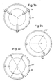
- 3a to 3c show various configurations of the spacer elements which radially cover the end face of the sacrificial anode (indicated by dashed lines).
- the spacer element 110 itself can be radially opaque and extend over the entire wall thickness of the tubular sacrificial anode.
- the same effect can be achieved in the course of one revolution of the sacrificial anode by individual spacing elements 110 ', 110 ⁇ , which do not individually cover the end face in a radially covering manner, as a result of their offset arrangement, as is made clear in FIGS. 3b and 3c.
- the spacer elements 110, 110 ′, 110 ⁇ advantageously allow the radial movement of the sacrificial anode, which is essential to the invention, by keeping the sacrificial anode free of deposits in a radially covering manner, but not restricting the freedom of movement. Since the tubular sacrificial anode 100 rests on the spacer elements due to its own weight, the spacer elements also serve as wiping elements which keep the end face of the tubular sacrificial anode free of passivation layers. This effect is reinforced by the fact that the surface of the spacer elements is formed such that the contact takes place essentially along a radial line.
- the spacer elements are fastened in the fixed cathode 101 in such a way that they are easy to replace and the gap can be adjusted in a simple manner.
- the spacer elements 110 shown in FIG. 3a, are guided in a corresponding recess in the cathode 101 and can be pulled radially outward from these recesses.
- the cylindrical spacers 110 'and 110' ', shown in Fig. 3b and 3c are inserted through corresponding holes in the cathode 101 and can also be easily replaced axially.
- the controlled radial play of the tubular sacrificial anode 100 greatly contributes to uniform removal of the end face and thus to uniform consumption of the sacrificial anode, the gap 103 always maintaining a constant size defined by the spacing elements. The residues removed from the end face are flushed out of the gap by the emulsion.
- the current is supplied with the aid of contact pliers via a collector ring 111.
- the collector ring 111 is driven by the drive 105 and rotates synchronously with the sacrificial anode 100.
- the rotating collector ring 111 is electrically connected to the sacrificial anode 100 by a flexible fabric conductor 120.
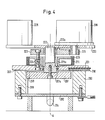
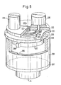
- FIGS. 4 and 5 show a second exemplary embodiment of the device according to the invention, which has a standing tubular sacrificial anode 200 and a rotating flat cathode 201 opposite it. Between the end face of the tubular sacrificial anode 200 and the flat cathode 201 there is a gap 203 with a constant spacing, which is maintained by spacing elements 210 and through which the emulsion passes from the inside of the tubular sacrificial anode 200. The emulsion is supplied through an inflow 204 in a flat plate 202 which closes the tubular sacrificial anode 200 downward.
- the tubular one forms inside Sacrificial anode is a cavity closed by flat plate 202 and by cathode 201.
- the emulsion can only escape from the cavity through the gap 203, so that it is possible to achieve a higher flow rate of the emulsion in the gap if the emulsion is supplied with sufficient pressure.
- the cathode 201 lies vertically above the sacrificial anode and is driven by the drive 205.
- the drive is arranged on a base plate 220 which is axially movably connected to the sacrificial anode via an axis 222. This connection is accomplished by a coupling star 207, which engages with its projections 208 in axial grooves 209 in the inner lateral surface of the tubular sacrificial anode.
- the rigid connection between the base plate 220, axis 222 and coupling star 207 causes the torque that is applied by the drive 205 to be supported in the longitudinal grooves 209 of the fixed sacrificial anode 200.
- the drive pinion 221 of the drive 205 drives a spur gear 223 which is rotatably mounted on the axis 222 via a bearing 223a.
- the spur gear 223 is connected via bolts 224 to an insulating disk 225 which is rotatably arranged on the axis 222 via a bearing 225a and which has a collector ring 211 on its circumference, via which the current is supplied with the aid of contact pliers.
- the disk 225 Via the bolts 224, the disk 225 is connected to the flat cathode 201, which is mounted on the axis 222 via a bearing 201a.
- the drive pinion 221, the spur gear 223, the insulating disk 225 and the flat cathode 201 rotate synchronously.
- the drive device and the cathode can be placed together on the sacrificial anode 200 from above and rest during operation with the dead weight of the cathode 201 and the drive 205 and the movement-transmitting parts on the end face of the sacrificial anode.
- a counterweight 226 which, with respect to the axis of rotation A, compensates for the one-sided loading of the base plate 220 by the drive 205.
- the emulsion Due to the total weight of the parts resting on the tubular sacrificial anode, it is possible, as already mentioned, for the emulsion to be passed under pressure into the interior of the sacrificial anode 200, so that the emulsion flows through the gap 203 at a higher flow rate.
- the controlled radial movement of the cathode 201 which is achieved by appropriately designing the play between the grooves 209 of the sacrificial anode 200 and the projections 208 of the coupling star 207, greatly contributes to uniform removal of the end face and thus to uniform consumption of the sacrificial anode .
- the Spacers 210 define a constant size of the gap 203 that is maintained during operation. The residues removed from the end face are flushed out of the electrode gap by the emulsion.
- the spacer elements 210 shown in FIG. 4 can be pulled radially out of the cathode 201 and are essentially designed like the spacer elements shown in FIG. 3a, which extend radially over the entire wall thickness of the tubular sacrificial anode.
- the use of the spacer elements which have been redesigned in accordance with FIGS. 3b and 3c and which are not individually radially covering, but which achieve the same effect as a result of the displacement when the cathode 201 is rotated, is likewise possible in the second exemplary embodiment of the device according to the invention.
Abstract
Description
Die Erfindung betrifft eine Vorrichtung zur Trennung von Emulsionen, insbesondere Öl/Wasser-Emulsionen durch elektrolytische Behandlung.The invention relates to a device for separating emulsions, in particular oil / water emulsions, by electrolytic treatment.
In vielen industriellen Prozessen ist heutzutage die Verwendung von Ölen, Emulgatoren, Dispersionsmitteln, Waschlaugen, Co-Polymeren und anderen durch Filter nicht zu entfernende Stoffe eine absolute Notwendigkeit. In fast allen Fällen kommen die verwendeten Stoffe mit Wasser in Berührung, was Probleme bei der Entsorgung des verunreinigten Wassers bereitet.In many industrial processes, the use of oils, emulsifiers, dispersants, wash liquors, copolymers and other substances that cannot be removed by filters is an absolute necessity. In almost all cases, the substances used come into contact with water, which creates problems in the disposal of the contaminated water.
Obwohl das Problem der Auftrennung von belasteten Emulsionsabwässern seit vielen Jahren besteht und eine derartige Trennung auch mittels unterschiedlicher bekannter Methoden durchgeführt wird, ist durch die Entwicklung und Verwendung immer neuer Stoffe die Bereitstellung eines wirtschaftlichen Verfahrens immer schwieriger geworden.Although the problem of separating contaminated emulsion waste water has existed for many years and such separation is also carried out using different known methods, the development and use of ever new substances has made it increasingly difficult to provide an economical process.
Zu den vorgeschlagenen Verfahren gehört auch die elektrolytischen Abwasserbehandlung. Dabei besteht die Anode der dabei eingesetzten Elektrolyseeinheit aus einem Material, vorzugsweise aus Aluminium oder Eisen, das sich während der Elektrolyse unter Ionenbildung auflöst unddurch das dabei die in der Emulsion vorhandenen Stoffe flockierbar sind. An der Kathode wird im wesentlichen Wasserstoff gebildet, das die in der Emulsion gebildeten Flocken aufschwimmen läßt. Der in einem nachgeschalteten Trennbehälter aufschwimmende Schaum wird abgestreift, absinkende Bestandteile in einem weiteren Trennbehälter abgezogen und das geklärte Wasser dem Behälter entnommen.The proposed processes also include electrolytic wastewater treatment. The anode of the electrolysis unit used here consists of a material, preferably aluminum or iron, which dissolves during the electrolysis with the formation of ions and through which the substances present in the emulsion can be flocculated. Essentially, on the cathode Hydrogen is formed, which allows the flakes formed in the emulsion to float. The foam floating in a downstream separation tank is stripped off, sinking constituents are drawn off in a further separation tank and the clarified water is removed from the tank.
Ein wesentliches Problem dieses Elektrolyseverfahrens ist darin zu sehen, daß der kontinuierliche, gleichmäßige Abtrag der Opferanode ohne Entfernen von Ablagerungen von der Oberfläche der Opferanode nicht möglich ist, da es durch diese Ablagerungen zu unzulässigen Änderungen der Höhe des Elektrodenspalts, sowie zu einer Passivierung der Opferanode kommt.A major problem with this electrolysis process is that it is not possible to remove the sacrificial anode continuously and evenly without removing deposits from the surface of the sacrificial anode, since these deposits lead to inadmissible changes in the height of the electrode gap and to passivation of the sacrificial anode is coming.
Eine Vorrichtung zum Abtragen der Passivierungsschicht ist in der DE-AS 24 21 266 beschrieben. Die Kathode dieser Vorrichtung ruht mit ihrem Eigengewicht auf einer massiven Opferanode, wobei der Spalt zwischen der Kathode und der Opferanode durch Abstandselemente aufrecht erhalten wird. Diese Abstandselemente sind aus einem nicht leitenden, abriebfesten Material hergestellt und liegen auf der Stirnfläche der Opferanode auf. Die Zuführung des Abwassers zum Elektrodenspalt erfolgt durch eine zentrale Bohrung in der Kathode unter Druck. Bei dieser bekannten Vorrichtung werden die Ablagerungen auf der Anode dadurch verhindert, daß einerseits die Emulsion mit einer hohen Strömungsgeschwindigkeit durch den Spalt gepreßt wird und andererseits die Kathode in einer oszillierenden konzentrischen Drehbewegung relativ zur feststehenden Anode bewegt wird, so daß die Abstandselemente in der Kathode durch eine Schabwirkung die Ablagerungen auf der Oberfläche der Anode entfernen.A device for removing the passivation layer is described in DE-AS 24 21 266. The cathode of this device rests with its own weight on a massive sacrificial anode, the gap between the cathode and the sacrificial anode being maintained by spacing elements. These spacer elements are made of a non-conductive, abrasion-resistant material and rest on the end face of the sacrificial anode. The waste water is fed to the electrode gap through a central bore in the cathode under pressure. In this known device, the deposits on the anode are prevented in that, on the one hand, the emulsion is pressed through the gap at a high flow rate and, on the other hand, the cathode is moved in an oscillating concentric rotary movement relative to the fixed anode, so that the spacer elements in the cathode pass through a scraping action removes the deposits on the surface of the anode.
Trotz der genannten Maßnahmen wird bei der bekannten Vorrichtung die Opferanode im Bereich der Zuflußöffnung in der Kathode nicht wirksam von Ablagerungen befreit, weil bei einem ungleichen Abrieb an der Stirnfläche der Anode, z.B. aufgrund von Unregelmäßigkeiten an den Abstandselementen in den dadurch erzeugten Tälern in der Stirnfläche der Anode dort die passivierenden Ablagerungen nicht entfernt werden. Darüber hinaus kommt es im Bereich der Zuflußöffnung zu unkontrollierbaren Erodierungen, was Spaltungenauigkeiten im Kreisringspalt und unkontrollierbare Spaltströmungen zur Folge hat. Bei der Aufrechterhaltung optimaler Bedingungen im Kreisringspalt sind jedoch Unterschiede in der Größenordnung von 5/100 mm erheblich.Despite the measures mentioned, in the known device the sacrificial anode is not effectively freed of deposits in the area of the inflow opening in the cathode, because if there is uneven abrasion on the end face of the anode, e.g. due to irregularities in the spacer elements in the valleys produced in the end face of the anode, the passivating deposits are not removed there. In addition, there are uncontrollable erosions in the area of the inflow opening, which results in inaccurate splitting in the annular gap and uncontrollable gap flows. When maintaining optimal conditions in the annulus gap, however, differences in the order of 5/100 mm are considerable.
Der Erfindung liegt daher die Aufgabe zugrunde, eine Vorrichtung zur Trennung von Emulsionen zu schaffen, bei der die Passivierung der Oberfläche der Opferanode vollständig verhindert und die Opferanode gleichmäßig bei stets gleicher Spaltbreite abgetragen wird.The invention is therefore based on the object of providing a device for separating emulsions in which the passivation of the surface of the sacrificial anode is completely prevented and the sacrificial anode is removed evenly with the same gap width at all times.
Gelöst wird diese Aufgabe durch eine Vorrichtung zur Trennung von Emulsionen, bei der durch Elektrolyse Metallionen zur Bindung der emulgierten Stoffe in die Emulsion eingebracht werden, mit einer rohrförmigen Opferanode, mit einer Kathode, die einer Stirnfläche der Opferanode unter Bildung eines Spaltes gegenüberliegt, durch den die Emulsion hindurchtritt, mit an der Kathode angeordneten Abstandselementen, an denen zur Bestimmung der Höhe des Spaltes die Stirnfläche der Opferanode anliegt, und mit einem Antrieb, mit dem eine Drehbewegung zwischen der Kathode und der Opferanode um deren Achse erzeugt wird, bei der erfindungsgemäß der Antrieb mit der rohrförmigen Opferanode derart gekuppelt ist, daß in definierten Grenzen eine freie Radialbewegung zwischen Opferanode und Kathode möglich ist, die die Drehbewegung zwischen Opferanode und Kathode überlagert.This object is achieved by a device for separating emulsions, in which metal ions are introduced into the emulsion by means of electrolysis to bind the emulsified substances, with a tubular sacrificial anode, with a cathode, which lies opposite an end face of the sacrificial anode with the formation of a gap the emulsion passes through, with spacer elements arranged on the cathode, against which the end face of the sacrificial anode rests in order to determine the height of the gap, and with a drive with which a rotary movement between the cathode and the sacrificial anode is generated about its axis, in which, according to the invention, the Drive with the tubular sacrificial anode is coupled such that in defined limits, a free radial movement between sacrificial anode and cathode is possible, which overlaps the rotational movement between sacrificial anode and cathode.
Durch die erfindungsgemäße Vorrichtung wird sichergestellt, daß etwaige stellenweise auftretende Beschädigungen der Abstandselemente nicht durch die Schabwirkung auf die Oberfläche der Opferanode abgebildet werden, da die in der Spaltebene zugelassene radiale Bewegung der angetriebenen Elektrode, die sich der konzentrischen Bewegung überlagert stets einen gleichmäßigen Abtrag der Opferanode gewährleistet.The device according to the invention ensures that any damage to the spacer elements which may occur in places is not imaged by the scraping action on the surface of the sacrificial anode, since the radial movement of the driven electrode which is permitted in the splitting plane and which is superimposed on the concentric movement always results in uniform removal of the sacrificial anode guaranteed.
In einer ersten erfindungsgemäßen Ausführungsform ist der Antrieb ortsfest und es wird die Opferanode angetrieben, die vertikal über der Kathode angeordnet ist und mit ihrem Eigengewicht auf den Abstandselementen der Kathode aufliegt. Der Antrieb ist mit der Opferanode über eine in die Opferanode hineinragende Hohlwelle gekuppelt, an der ein Kollektorring starr befestigt ist.In a first embodiment according to the invention, the drive is stationary and the sacrificial anode is driven, which is arranged vertically above the cathode and rests with its own weight on the spacer elements of the cathode. The drive is coupled to the sacrificial anode via a hollow shaft protruding into the sacrificial anode, to which a collector ring is rigidly attached.
In einer zweiten erfindungsgemäßen Ausführungsform ist hingegen die Opferanode ortsfest angeordnet und es wird die Kathode angetrieben, die oberhalb der Opferanode liegt und die unter ihrem Eigengewicht und dem des Antriebs mit ihren Abstandselementen auf der Stirnfläche der Opferanode aufliegt. Der Antrieb ist dabeiauf einer Grundplatte angeordnet, die mit der Opferanode axial beweglich über eine Achse verbunden ist, auf der die Kathode drehbar angeordnet ist. Ein Kollektorring ist ebenfalls drehbar auf der Achse gelagert und gemeinsam mit der Kathode mit dem Antrieb gekuppelt.In a second embodiment according to the invention, however, the sacrificial anode is arranged in a fixed position and the cathode is driven, which lies above the sacrificial anode and which rests on the end face of the sacrificial anode under its own weight and that of the drive with its spacing elements. The drive is arranged on a base plate which is axially movably connected to the sacrificial anode via an axis on which the cathode is rotatably arranged. A collector ring is also rotatably mounted on the axle and coupled to the drive together with the cathode.
Bei den beiden Ausführungsformen erfolgt die unmittelbare Kupplung zwischen dem Antrieb und der Opferanode durch einen zur Drehachse senkrecht angeordneten Kupplungsstern, der mit seinen Vorsprüngen in axiale Nuten der inneren Mantelfläche der rohrförmigen Opferanode eingreift.In the two embodiments, the direct coupling between the drive and the sacrificial anode takes place through a coupling star which is arranged perpendicular to the axis of rotation and which engages with its projections in axial grooves of the inner circumferential surface of the tubular sacrificial anode.
Die unmittelbare Kupplung zwischen Antrieb und Opferanode erfolgt in einer anderen Variante durch Stangen, die in axiale Bohrungen in der Wand der Opferanode eingreifen.In another variant, the direct coupling between the drive and the sacrificial anode takes place by means of rods which engage in axial bores in the wall of the sacrificial anode.
Weitere Ausgestaltungen der erfindungsgemäßen Vorrichtung ergeben sich im übrigen aus den Unteransprüchen.Further refinements of the device according to the invention result from the subclaims.
Die Erfindung wird im folgenden anhand der schematisch ausgeführten Zeichnungen näher erläutert.The invention is explained below with reference to the schematically executed drawings.
Dabei zeigt:
- Fig. 1 einen Längsschnitt durch die erste Ausführungsform der erfindungsgemäßen Vorrichtung,
- Fig. 2 eine perspektivische Ansicht der erfindungsgemäßen Vorrichtung aus Fig. 1,
- Fig. 3a - 3c unterschiedliche Anordnungen und Ausgestaltungen der Abstandselemente in der Kathode,
- Fig. 4 einen Längsschnitt durch die zweite Ausführungsform der erfindungsgemäßen Vorrichtung, und
- Fig. 5 eine perspektivische Ansicht der Vorrichtung aus Fig. 4.
- 1 shows a longitudinal section through the first embodiment of the device according to the invention,
- 2 shows a perspective view of the device according to the invention from FIG. 1,
- 3a-3c different arrangements and configurations of the spacer elements in the cathode,
- Fig. 4 is a longitudinal section through the second embodiment of the device according to the invention, and
- 5 shows a perspective view of the device from FIG. 4.
In den Fig. 1 und 2 ist ein erstes Ausführungsbeispiel für eine Elektrolysevorrichtung gemäß der Erfindung dargestellt, die eine rohrförmige Opferanode 100 und eine ihr gegenüberliegende ebene Kathode 101 aufweist. Zwischen der Stirnfläche der rohrförmigen Opferanode 100 und der ebenen Kathode 101 besteht ein Spalt 103 mit konstantem Abstand, durch den die Emulsion aus dem Inneren der rohrförmigen Opferanode 100 hindurchtritt. Zugeführt wird die Emulsion durch einen Zufluß 104 in der Kathode, so daß sich im Inneren der rohrförmigen Opferanode 100 ein Flüssigkeitsspiegel mit entsprechender Höhe einstellt. Der Zufluß der Emulsion kann auch von oben durch die obere Öffnung der Opferanode erfolgen.1 and 2 show a first exemplary embodiment of an electrolysis device according to the invention, which has a tubular
Ein Antrieb 105 ermöglicht eine Drehbewegung zwischen der rohrförmigen Opferanode 100 und der feststehenden Kathode 101. Dazu wird die Antriebsbewegung vom Antrieb 105 über eine Hohlwelle 106 auf eine Scheibe 107 übertragen, die auf ihrem Umfang Vorsprünge 108 aufweist, die in entsprechende in Achsrichtung verlaufende Nuten 109 in der Innenwand der rohrförmigen Opferanode 100 eingreifen. Dieser Eingriff zwischen den Vorsprüngen 108 und den Nuten 109 ist erfindungsgemäß mit radialem Spiel ausgebildet, so daß die rohrförmige Opferanode 100 um ihre Längsachse eine gewisse Radialbewegung ausführen kann, die sich der Drehbewegung überlagert.A
Der Antrieb kann nach einer nicht dargestellten Variante mit Hilfe von Stangen in Bohrungen eingreifen, die in der Wandung der rohrförmigen Opferanode vorgesehen sind und die sich in Längsrichtung der Opferanode erstrecken. Auch bei dieser Ausgestaltung bleibt durch geeignete Dimensionierung der Bohrung und der Stäbe der rohrförmigen Opferanode ein definiertes radiales Spiel, so daß die Opferanode mit einer ausreichenden radialen Bewegungsfreiheit auf den Abstandselementen aufzuliegen und so an ihrer Stirnfläche durch die Schabwirkung gleichmäßig abgetragen werdem kann.According to a variant which is not shown, the drive can engage with the aid of rods in bores which are provided in the wall of the tubular sacrificial anode and which extend in the longitudinal direction of the sacrificial anode. In this embodiment, too, a defined radial play remains through suitable dimensioning of the bore and the rods of the tubular sacrificial anode, so that the To lay the sacrificial anode with sufficient radial freedom of movement on the spacer elements and so it can be removed evenly on its end face by the scraping effect.
Die rohrförmigen Opferanode 100 wird, wie schon erwähnt, durch Abstandselemente 110, die in der ebenen Kathode 101 vorgesehen sind, in entsprechendem Abstand zur Kathode gehalten. Auf diesen Abstandselementen 110 ruht die rohrförmige Opferanode 100 aufgrund ihres Eigengewichts.As already mentioned, the tubular
In den Fig. 3a bis 3c sind verschiedene Ausgestaltungen der Abstandselemente dargestellt, die die Stirnfläche der Opferanode (gestrichelt angedeutet) radial deckend überstreichen. Dabei kann, wie in Fig. 3a gezeigt, das Abstandselement 110 selbst radial deckend sein und sich über die gesamte Wanddicke der rohrförmigen Opferanode erstrecken. Der gleiche Effekt kann im Verlauf einer Umdrehung der Opferanode durch einzelne Abstandselemente 110′, 110˝, die einzeln nicht radial deckend die Stirnfläche überstreichen, in Folge ihrer versetzten Anordnung erzielt werden, wie dies in den Fig. 3b und 3c deutlich gemacht ist.3a to 3c show various configurations of the spacer elements which radially cover the end face of the sacrificial anode (indicated by dashed lines). In this case, as shown in FIG. 3a, the
In der Spaltebene lassen vorteilhaft die Abstandselemente 110, 110′, 110˝ die erfindungswesentliche Radialbewegung der Opferanode zu, indem sie zwar radial deckend die Opferanode von Ablagerungen freihalten, aber die Bewegungsfreiheit nicht einschränken. Da die rohrförmige Opferanode 100 auf den Abstandselementen aufgrund ihres Eigengewichts ruht, dienen die Abstandselemente gleichzeitig als Abstreifelemente, die die Stirnfläche der rohrförmigen Opferanode von Passivierungsschichten freihält. Dieser Effekt wird verstärkt durch die Tatsache, daß die Oberfläche der Abstandselemente so ausgebildet ist, daß die Berührung im wesentlichen entlang einer radialen Linie stattfindet.In the splitting plane, the
Die Abstandselemente sind in der feststehenden Kathode 101 so befestigt, daß sie leicht auszuwechseln sind und der Spalt auf einfache Art nachstellbar ist. So sind die Abstandselemente 110, dargestellt in Fig. 3a in einer entsprechenden Ausnehmung in der Kathode 101 geführt und können radial nach außen aus diesen Ausnehmungen herausgezogen werden. Die zylindrischen Abstandselemente 110′ und 110'′, dargestellt in Fig. 3b und 3c sind durch entsprechende Bohrungen in der Kathode 101 hindurchgesteckt und können axial ebenfalls leicht ausgetauscht werden.The spacer elements are fastened in the
Erfindungsgemäß trägt das kontrollierte radiale Spiel der rohrförmigen Opferanode 100 in großem Maße zu einem gleichmäßigen Abtragen der Stirnfläche und damit zu einem gleichmäßigen Verbrauch der Opferanode bei, wobei der Spalt 103 stets eine konstante, durch die Abstandselemente festgelegte Größe beibehält. Die von der Stirnfläche abgetragenen Rückstände werden durch die Emulsion aus dem Spalt gespült.According to the invention, the controlled radial play of the tubular
In dem in den Fig. 1 und 2 dargestellten Ausführungsbeispiel der erfindungsgemäßen Vorrichtung ist vorgesehen, daß mit Hilfe einer Kontaktzange über einen Kollektorring 111 die Stromzuführung erfolgt. Der Kollektorring 111 wird wie die Opferanode 100 durch den Antrieb 105 angetrieben und dreht sich synchron mit der Opferanode 100. Der rotierende Kollektorring 111 ist mit der Opferanode 100 durch einen flexiblen Gewebeleiter 120 elekrisch verbunden.In the embodiment of the device according to the invention shown in FIGS. 1 and 2, it is provided that the current is supplied with the aid of contact pliers via a
In den Fig. 4 und 5 ist ein zweites Ausführungsbeispiel der erfindungsgemäßen Vorrichtung dargestellt, die eine stehende rohrförmige Opferanode 200 und eine ihr gegenüberliegende drehende ebene Kathode 201 aufweist. Zwischen der Stirnfläche der rohrförmigen Opferanode 200 und der ebenen Kathode 201 besteht ein Spalt 203 mit konstantem Abstand, der durch Abstandselemente 210 aufrecht erhalten wird und durch den die Emulsion aus dem Inneren der rohrförmigen Opferanode 200 hindurchtritt. Zugeführt wird die Emulsion durch einen Zufluß 204 in einer die rohrförmige Opferanode 200 nach unten abschließenden, ebenen Platte 202. Da die Kathode 201 unter ihrem Eigengewicht und dem Gewicht des weiter unten beschriebenen Antriebs auf der rohrförmigen Opferanode 200 aufliegt, bildet sich im Inneren der rohrförmigen Opferanode ein durch die ebene Platte 202 und durch die Kathode 201 abgeschlossener Hohlraum. Die Emulsion kann lediglich durch den Spalt 203 aus dem Hohlraum entweichen, so daß es möglich ist, im Spalt eine höhere Strömungsgeschwindigkeit der Emulsion zu erzielen, wenn die Emulsion mit ausreichendem Druck zugeführt wird.4 and 5 show a second exemplary embodiment of the device according to the invention, which has a standing tubular
Die Kathode 201 liegt vertikal oberhalb der Opferanode und wird durch den Antrieb 205 angetrieben. Der Antrieb ist auf einer Grundplatte 220 angeordnet, die über eine Achse 222 axial beweglich mit der Opferanode verbunden ist. Diese Verbindung wird durch einen Kupplungsstern 207 bewerkstelligt, der mit seinen Vorsprüngen 208 in axiale Nuten 209 in der inneren Mantelfläche der rohrförmigen Opferanode eingreift. Die starre Verbindung zwischen der Grundplatte 220, Achse 222 und Kupplungsstern 207 bewirkt, daß sich das Drehmoment, das durch den Antrieb 205 aufgebracht wird, in den Längsnuten 209 der feststehenden Opferanode 200 abstützt.The
Das Antriebsritzel 221 des Antriebs 205 treibt ein Stirnrad 223 an, das über ein Lager 223a drehbar auf der Achse 222 gelagert ist. Das Stirnrad 223 ist über Bolzen 224 mit einer isolierenden Scheibe 225 verbunden, die über ein Lager 225a drehbar auf der Achse 222 angeordnet ist und die auf ihrem Umfang einen Kollektorring 211 trägt, über den mit Hilfe einer Kontaktzange die Stromzuführung erfolgt. Über die Bolzen 224 ist die Scheibe 225 mit der ebenen Kathode 201 verbunden, die über ein Lager 201a auf der Achse 222 gelagert ist. Durch das Antriebsritzel 221 angetrieben, rotieren das Stirnrad 223, die isolierende Scheibe 225 und die ebene Kathode 201 synchron.The
Die Antriebsvorrichtung und die Kathode können zusammen von oben auf die Opferanode 200 aufgesetzt werden und ruhen während des Betriebs mit dem Eigengewicht der Kathode 201 sowie des Antriebs 205 und der die Bewegung übertragenden Teile auf der Stirnfläche der Opferanode. Hinzu kommt das Gewicht eines Gegengewichts 226, das in Bezug auf die Drehachse A die einseitige Belastung der Grundplatte 220 durch den Antrieb 205 ausgleicht.The drive device and the cathode can be placed together on the
Durch das Gesamtgewicht der auf der rohrförmigen Opferanode ruhenden Teile ist es möglich, daß die Emulsion, wie bereits zuvor erwähnt, unter Druck in den Innenraum der Opferanode 200 geleitet werden kann, so daß die Emulsion mit einer höheren Strömungsgeschwindigkeit durch den Spalt 203 strömt. Erfindungsgemäß trägt die kontrollierte Radialbewegung der Kathode 201, das durch entsprechende Ausgestaltung des Spiels zwischen den Nuten 209 der Opferanode 200 und den Vorsprüngen 208 des Kupplungssterns 207 erzielt wird, in großem Maße zu einem gleichmäßigen Abtrag der Stirnfläche und damit zu einem gleichmäßigen Verbrauch der Opferanode bei. Die Abstandselemente 210 legen eine konstante Größe des Spalts 203 fest, die während des Berriebs beibehalten wird. Die von der Stirnfläche abgetragenen Rückstände werden durch die Emulsion aus dem Elektrodenspalt gespült.Due to the total weight of the parts resting on the tubular sacrificial anode, it is possible, as already mentioned, for the emulsion to be passed under pressure into the interior of the
Die in der Fig. 4 dargestellten Abstandselemente 210 können radial aus der Kathode 201 herausgezogen werden und sind im wesentlichen wie die in der Fig. 3a dargestellten Abstandselemente ausgebildet, die sich radial deckend über die gesamte Wanddicke der rohrförmigen Opferanode erstrecken. Der Einsatz der entsprechend den Fig. 3b und 3c umgebildeten Abstandselemente, die einzeln nicht radial deckend sind, die aber in Folge der Versetzung bei einer Umdrehung der Kathode 201 denselben Effekt erzielen, ist beim zweiten Ausführungsbeispiel der erfindungsgemäßen Vorrichtung ebenfalls möglich.The
Claims (14)
- einer rohrförmigen Opferanode (100;200),
- einer Kathode (101; 201), die einer Stirnfläche der Opferanode unter Bildung eines Spaltes (103;203) gegenüberliegt, durch den die Emulsion hindurchtritt,
- an der Kathode angeordneten Abstandselementen (110;210), an denen zur Bestimmung der Höhe des Spaltes die Stirnfläche der Opferanode anliegt, und
- einem Antrieb (105; 205), mit dem eine Drehbewegung zwischen der Kathode und der Opferanode um deren Achse (A) erzeugt wird,
dadurch gekennzeichnet,
- daß der Antrieb (105; 205) mit der rohrförmigen Opferanode (100; 200) derart gekuppelt ist, daß in definierten Grenzen eine freie Radialbewegung zwischen Opferanode und Kathode möglich ist, die die Drehbewegung zwischen Opferanode und Kathode überlagert.1. Device for separating emulsions, in which metal ions for binding the emulsified substances are introduced into the emulsion by electrolysis with
- a tubular sacrificial anode (100; 200),
a cathode (101; 201), which lies opposite an end face of the sacrificial anode, forming a gap (103; 203) through which the emulsion passes,
- Spacer elements (110; 210) arranged on the cathode, against which the end face of the sacrificial anode rests to determine the height of the gap, and
a drive (105; 205) with which a rotary movement between the cathode and the sacrificial anode is generated about the axis (A) thereof,
characterized by
- That the drive (105; 205) with the tubular sacrificial anode (100; 200) is coupled such that a free radial movement between the sacrificial anode and cathode is possible, which overlaps the rotational movement between the sacrificial anode and cathode.
dadurch gekennzeichnet, daß die Kupplung zwischen Antrieb und Opferanode eine axiale Bewegung zwischen der Opferanode und dem Antrieb zuläßt.2. Device according to claim 1,
characterized in that the coupling between the drive and the sacrificial anode allows axial movement between the sacrificial anode and the drive.
dadurch gekennzeichnet, daß der Antrieb (105) ortsfest ist und die Opferanode (100) angetrieben wird (Fig. 1 und 2).3. Device according to claim 1 or 2,
characterized in that the drive (105) is stationary and the sacrificial anode (100) is driven (Fig. 1 and 2).
dadurch gekennzeichnet, daß die Opferanode (100) vertikal über der Kathode (101) angeordnet ist und mit ihrem Eigengewicht auf den Abstandselementen (110) der Kathode aufliegt (Fig. 1 und 2).4. The device according to claim 3,
characterized in that the sacrificial anode (100) is arranged vertically above the cathode (101) and rests with its own weight on the spacer elements (110) of the cathode (FIGS. 1 and 2).
dadurch gekennzeichnet, daß die Antriebsvorrichtung (105) die rohrförmige Opferanode (100) über eine Hohlwelle (106) antreibt, die in die Opferanode hineinragt (Fig. 1 und 2).5. The device according to claim 3 or 4,
characterized in that the drive device (105) drives the tubular sacrificial anode (100) via a hollow shaft (106) which projects into the sacrificial anode (FIGS. 1 and 2).
dadurch gekennzeichnet, daß auf der Hohlwelle (106) ein Kollektorring (111) fest mit der Hohlwelle verbunden angeordnet ist (Fig. 1 und 2).6. The device according to claim 5,
characterized in that on the hollow shaft (106) a collector ring (111) is fixedly connected to the hollow shaft (Fig. 1 and 2).
dadurch gekennzeichnet,
- daß die Opferanode (200) ortsfest angeordnet ist,
- daß die Kathode (201) vertikal oberhalb der Opferanode liegt und angetrieben wird, und
- daß die Kathode unter ihrem Eigengewicht und dem des Antriebs (205) mit ihren Abstandselementen (210) auf der Stirnfläche der Opferanode aufliegt (Fig. 4 und 5).7. The device according to claim 1 or 2,
characterized by
- That the sacrificial anode (200) is arranged stationary,
- That the cathode (201) is vertically above the sacrificial anode and is driven, and
- That the cathode rests under its own weight and that of the drive (205) with its spacer elements (210) on the end face of the sacrificial anode (Fig. 4 and 5).
dadurch gekennzeichnet,
- daß der Antrieb (205)auf einer Grundplatte (220) angeordnet ist,
- daß die Grundplatte über einer Achse (222) axial beweglich mit der Opferanode (200) verbunden ist, und
- daß die Kathode (201) auf der Achse (222) drehbar angeordnet ist (Fig. 4 und 5).8. The device according to claim 7,
characterized by
- That the drive (205) is arranged on a base plate (220),
- That the base plate is axially movably connected to the sacrificial anode (200) via an axis (222), and
- That the cathode (201) on the axis (222) is rotatably arranged (Fig. 4 and 5).
dadurch gekennzeichnet, daß auf der Achse (222) ein Kollektorring (211) drehbar gelagert ist und dieser gemeinsam mit der Kathode (201) mit dem Antrieb (205) gekuppelt ist (Fig. 4 und 5).9. The device according to claim 8,
characterized in that a collector ring (211) is rotatably mounted on the axis (222) and this is coupled together with the cathode (201) to the drive (205) (FIGS. 4 and 5).
dadurch gekennzeichnet, daß die unmittelbare Kupplung zwischen Antrieb und Opferanode durch Stangen erfolgt, die in axiale Bohrungen in der Wand der Opferanode eingreifen.11. The device according to one of claims 1 to 4,
characterized in that the direct coupling between the drive and sacrificial anode is carried out by rods which engage in axial bores in the wall of the sacrificial anode.
dadurch gekennzeichnet, daß die Abstandselemente (110, 110′, 110˝; 210) so ausgebildet sind, daß ein Linienkontakt mit der Stirnfläche der Opferanode (100; 200) stattfindet.12. Device according to one of the preceding claims,
characterized in that the spacer elements (110, 110 ′, 110˝; 210) are designed such that line contact with the end face of the sacrificial anode (100; 200) takes place.
dadurch gekennzeichnet, daß die Abstandselemente (110) radial verlaufend sich über die gesamte Wanddicke der rohrförmigen Opferanode erstrecken (Fig. 3a).13. Device according to one of the preceding claims,
characterized in that the spacer elements (110) extend radially over the entire wall thickness of the tubular sacrificial anode (Fig. 3a).
dadurch gekennzeichnet,
- daß jedes Abstandselement (110′, 110˝) in seiner Radialerstreckung kürzer ist als die Wanddicke der Opferanode, und
- daß mehrere Abstandselemente radial so versetzt sind, daß sie gemeinsam die gesamte Wanddicke der Opferanode überdecken (Fig. 3b und 3c).14. The device according to one of claims 1 to 12,
characterized by
- That each spacer element (110 ', 110˝) is shorter in its radial extent than the wall thickness of the sacrificial anode, and
- That several spacer elements are radially offset so that they together cover the entire wall thickness of the sacrificial anode (Fig. 3b and 3c).
Priority Applications (1)
| Application Number | Priority Date | Filing Date | Title |
|---|---|---|---|
| AT89108190T ATE88369T1 (en) | 1988-05-11 | 1989-05-05 | DEVICE FOR THE ELECTROLYTIC SEPARATION OF EMULSIONS. |
Applications Claiming Priority (2)
| Application Number | Priority Date | Filing Date | Title |
|---|---|---|---|
| DE3816226 | 1988-05-11 | ||
| DE3816226A DE3816226A1 (en) | 1988-05-11 | 1988-05-11 | DEVICE FOR ELECTROLYTIC SEPARATION OF EMULSIONS |
Publications (3)
| Publication Number | Publication Date |
|---|---|
| EP0341614A2 true EP0341614A2 (en) | 1989-11-15 |
| EP0341614A3 EP0341614A3 (en) | 1990-09-26 |
| EP0341614B1 EP0341614B1 (en) | 1993-04-21 |
Family
ID=6354239
Family Applications (1)
| Application Number | Title | Priority Date | Filing Date |
|---|---|---|---|
| EP89108190A Expired - Lifetime EP0341614B1 (en) | 1988-05-11 | 1989-05-05 | Apparatus for the electrolytic separation of emulsions |
Country Status (5)
| Country | Link |
|---|---|
| EP (1) | EP0341614B1 (en) |
| AT (1) | ATE88369T1 (en) |
| DE (2) | DE3816226A1 (en) |
| ES (1) | ES2039743T3 (en) |
| GR (1) | GR3008542T3 (en) |
Cited By (4)
| Publication number | Priority date | Publication date | Assignee | Title |
|---|---|---|---|---|
| WO1994014708A1 (en) * | 1992-12-18 | 1994-07-07 | Sp/Wm Dricksvatten Ab | A device for separation of emulsions by electrochemical precipitation |
| WO1994014709A1 (en) * | 1992-12-22 | 1994-07-07 | Jan Sundell | Apparatus for purifying water |
| US5372690A (en) * | 1992-05-13 | 1994-12-13 | Recra Environmental, Inc. | Apparatus for removing contaminants from an aqueous medium |
| WO2001068532A1 (en) * | 2000-03-15 | 2001-09-20 | Ozcent Pty Ltd | Electrolysis based water treatment |
Families Citing this family (3)
| Publication number | Priority date | Publication date | Assignee | Title |
|---|---|---|---|---|
| ES2292310B1 (en) * | 2005-09-09 | 2009-02-01 | Procontrol, S.L. | SYSTEM FOR THE TREATMENT OF EFFLUENTS BY ELECTROCOAGULATION. |
| ES2326447B1 (en) * | 2007-01-29 | 2010-07-09 | Procontrol, S.L. | SYSTEM FOR THE TREATMENT OF EFFLUENTS BY ELECTRO-COAGULATION. |
| DE102015215037B4 (en) * | 2015-08-06 | 2021-02-25 | Fraunhofer-Gesellschaft zur Förderung der angewandten Forschung e.V. | Reactor with sacrificial anode |
Citations (4)
| Publication number | Priority date | Publication date | Assignee | Title |
|---|---|---|---|---|
| US2399289A (en) * | 1940-06-15 | 1946-04-30 | Aqua Electric Corp Ltd | Apparatus for purifying liquids |
| DE2238844A1 (en) * | 1971-08-06 | 1973-02-15 | Rast | CHLORINATION PLANT |
| US3944478A (en) * | 1973-05-02 | 1976-03-16 | Mitsubishi Denki Kabushiki Kaisha | Electrolytic drainage treating apparatus |
| US4236990A (en) * | 1979-05-29 | 1980-12-02 | King Arthur S | Treater with self-cleaning electrodes |
-
1988
- 1988-05-11 DE DE3816226A patent/DE3816226A1/en not_active Withdrawn
-
1989
- 1989-05-05 ES ES198989108190T patent/ES2039743T3/en not_active Expired - Lifetime
- 1989-05-05 DE DE8989108190T patent/DE58904106D1/en not_active Expired - Fee Related
- 1989-05-05 AT AT89108190T patent/ATE88369T1/en not_active IP Right Cessation
- 1989-05-05 EP EP89108190A patent/EP0341614B1/en not_active Expired - Lifetime
-
1993
- 1993-07-21 GR GR930400187T patent/GR3008542T3/el unknown
Patent Citations (4)
| Publication number | Priority date | Publication date | Assignee | Title |
|---|---|---|---|---|
| US2399289A (en) * | 1940-06-15 | 1946-04-30 | Aqua Electric Corp Ltd | Apparatus for purifying liquids |
| DE2238844A1 (en) * | 1971-08-06 | 1973-02-15 | Rast | CHLORINATION PLANT |
| US3944478A (en) * | 1973-05-02 | 1976-03-16 | Mitsubishi Denki Kabushiki Kaisha | Electrolytic drainage treating apparatus |
| US4236990A (en) * | 1979-05-29 | 1980-12-02 | King Arthur S | Treater with self-cleaning electrodes |
Cited By (7)
| Publication number | Priority date | Publication date | Assignee | Title |
|---|---|---|---|---|
| US5372690A (en) * | 1992-05-13 | 1994-12-13 | Recra Environmental, Inc. | Apparatus for removing contaminants from an aqueous medium |
| US5558755A (en) * | 1992-05-13 | 1996-09-24 | Recra Environmental, Inc. | Method for removing contaminants from an aqueous medium |
| WO1994014708A1 (en) * | 1992-12-18 | 1994-07-07 | Sp/Wm Dricksvatten Ab | A device for separation of emulsions by electrochemical precipitation |
| WO1994014709A1 (en) * | 1992-12-22 | 1994-07-07 | Jan Sundell | Apparatus for purifying water |
| EP0675855B1 (en) * | 1992-12-22 | 1999-03-24 | SUNDELL, Jan | Apparatus for purifying water |
| WO2001068532A1 (en) * | 2000-03-15 | 2001-09-20 | Ozcent Pty Ltd | Electrolysis based water treatment |
| US6800206B2 (en) | 2000-03-15 | 2004-10-05 | Ozcent Pty Ltd. | Electrolysis based water treatment |
Also Published As
| Publication number | Publication date |
|---|---|
| EP0341614B1 (en) | 1993-04-21 |
| DE58904106D1 (en) | 1993-05-27 |
| DE3816226A1 (en) | 1989-11-16 |
| EP0341614A3 (en) | 1990-09-26 |
| GR3008542T3 (en) | 1993-10-29 |
| ATE88369T1 (en) | 1993-05-15 |
| ES2039743T3 (en) | 1993-10-01 |
Similar Documents
| Publication | Publication Date | Title |
|---|---|---|
| DE917658C (en) | Method and device for cleaning centrifugal drums with a conical disc insert with a washing liquid | |
| DE3047013C2 (en) | Dispersing device for the processing of waste paper | |
| DE2551030C3 (en) | Wastewater treatment device with a device with magnets rotating around a shaft | |
| DE102017205551A1 (en) | Bottle treating machine and method for cleaning the pump / nozzle guard of the bottle treating machine | |
| DE3740230A1 (en) | PROCESSING UNIT FOR POINT ELECTRODES | |
| DE2024797C3 (en) | Filter press with vertically hanging filter plates | |
| EP0341614B1 (en) | Apparatus for the electrolytic separation of emulsions | |
| CH688282A5 (en) | Galvanic plating apparatus. | |
| DE2640803C2 (en) | Lamella separator for sedimentation | |
| DE3134861C2 (en) | Magnetic filter | |
| DE2238844A1 (en) | CHLORINATION PLANT | |
| DE69914018T2 (en) | Integrated electrolytic polishing process for the outer surface of metallic pipes and light-sensitive drum substrate produced in this way | |
| DE3805813A1 (en) | METHOD AND DEVICE FOR REGENERATING ION EXCHANGER MATERIAL | |
| DE3345124A1 (en) | DEVICE FOR TREATING OBJECTS WITH A TREATMENT LIQUID | |
| DE1610244B1 (en) | Device for the internal and external cleaning of a tubular object | |
| DE4128210A1 (en) | FILTERS FOR LIQUIDS | |
| DE3426742A1 (en) | Apparatus for sludge water discharge for sewage sludge thickeners | |
| DE964322C (en) | Method and device for filtering liquids | |
| DE2405931A1 (en) | DEVICE FOR REMOVING DEPOSITS ON THE EDGE OF A PLATE | |
| DE3234322C2 (en) | Filter element | |
| DE2631828C2 (en) | Galvanizing drum | |
| DE3445351A1 (en) | WATER SOFTENING SYSTEM | |
| DE2844145C3 (en) | Method and device for washing pulp | |
| DE2434943A1 (en) | DEVICE FOR REMOVING LIQUID FROM A SUSPENSION | |
| DE643509C (en) | Armouring on drum mills |
Legal Events
| Date | Code | Title | Description |
|---|---|---|---|
| PUAI | Public reference made under article 153(3) epc to a published international application that has entered the european phase |
Free format text: ORIGINAL CODE: 0009012 |
|
| AK | Designated contracting states |
Kind code of ref document: A2 Designated state(s): AT BE CH DE ES FR GB GR IT LI LU NL SE |
|
| PUAL | Search report despatched |
Free format text: ORIGINAL CODE: 0009013 |
|
| AK | Designated contracting states |
Kind code of ref document: A3 Designated state(s): AT BE CH DE ES FR GB GR IT LI LU NL SE |
|
| 17P | Request for examination filed |
Effective date: 19910207 |
|
| 17Q | First examination report despatched |
Effective date: 19910917 |
|
| GRAA | (expected) grant |
Free format text: ORIGINAL CODE: 0009210 |
|
| AK | Designated contracting states |
Kind code of ref document: B1 Designated state(s): AT BE CH DE ES FR GB GR IT LI LU NL SE |
|
| REF | Corresponds to: |
Ref document number: 88369 Country of ref document: AT Date of ref document: 19930515 Kind code of ref document: T |
|
| REF | Corresponds to: |
Ref document number: 58904106 Country of ref document: DE Date of ref document: 19930527 |
|
| GBT | Gb: translation of ep patent filed (gb section 77(6)(a)/1977) |
Effective date: 19930510 |
|
| ITF | It: translation for a ep patent filed |
Owner name: NOTARBARTOLO & GERVASI S.R.L. |
|
| EPTA | Lu: last paid annual fee | ||
| ET | Fr: translation filed | ||
| REG | Reference to a national code |
Ref country code: GR Ref legal event code: FG4A Free format text: 3008542 |
|
| REG | Reference to a national code |
Ref country code: ES Ref legal event code: FG2A Ref document number: 2039743 Country of ref document: ES Kind code of ref document: T3 |
|
| PLBE | No opposition filed within time limit |
Free format text: ORIGINAL CODE: 0009261 |
|
| STAA | Information on the status of an ep patent application or granted ep patent |
Free format text: STATUS: NO OPPOSITION FILED WITHIN TIME LIMIT |
|
| 26N | No opposition filed | ||
| EAL | Se: european patent in force in sweden |
Ref document number: 89108190.3 |
|
| PGFP | Annual fee paid to national office [announced via postgrant information from national office to epo] |
Ref country code: SE Payment date: 19960531 Year of fee payment: 8 Ref country code: NL Payment date: 19960531 Year of fee payment: 8 Ref country code: GR Payment date: 19960531 Year of fee payment: 8 Ref country code: FR Payment date: 19960531 Year of fee payment: 8 Ref country code: AT Payment date: 19960531 Year of fee payment: 8 |
|
| PGFP | Annual fee paid to national office [announced via postgrant information from national office to epo] |
Ref country code: LU Payment date: 19960601 Year of fee payment: 8 |
|
| PGFP | Annual fee paid to national office [announced via postgrant information from national office to epo] |
Ref country code: CH Payment date: 19960607 Year of fee payment: 8 |
|
| PGFP | Annual fee paid to national office [announced via postgrant information from national office to epo] |
Ref country code: BE Payment date: 19960612 Year of fee payment: 8 |
|
| PGFP | Annual fee paid to national office [announced via postgrant information from national office to epo] |
Ref country code: GB Payment date: 19960614 Year of fee payment: 8 Ref country code: DE Payment date: 19960614 Year of fee payment: 8 |
|
| PGFP | Annual fee paid to national office [announced via postgrant information from national office to epo] |
Ref country code: ES Payment date: 19960710 Year of fee payment: 8 |
|
| PG25 | Lapsed in a contracting state [announced via postgrant information from national office to epo] |
Ref country code: LU Free format text: LAPSE BECAUSE OF NON-PAYMENT OF DUE FEES Effective date: 19970505 Ref country code: GB Effective date: 19970505 Ref country code: AT Effective date: 19970505 |
|
| PG25 | Lapsed in a contracting state [announced via postgrant information from national office to epo] |
Ref country code: SE Effective date: 19970506 Ref country code: ES Free format text: LAPSE BECAUSE OF NON-PAYMENT OF DUE FEES Effective date: 19970506 |
|
| PG25 | Lapsed in a contracting state [announced via postgrant information from national office to epo] |
Ref country code: LI Free format text: LAPSE BECAUSE OF NON-PAYMENT OF DUE FEES Effective date: 19970531 Ref country code: CH Free format text: LAPSE BECAUSE OF NON-PAYMENT OF DUE FEES Effective date: 19970531 Ref country code: BE Effective date: 19970531 |
|
| BERE | Be: lapsed |
Owner name: SINTRA UMWELTSCHUTZTECHNIK G.M.B.H. Effective date: 19970531 |
|
| PG25 | Lapsed in a contracting state [announced via postgrant information from national office to epo] |
Ref country code: GR Free format text: THE PATENT HAS BEEN ANNULLED BY A DECISION OF A NATIONAL AUTHORITY Effective date: 19971130 |
|
| PG25 | Lapsed in a contracting state [announced via postgrant information from national office to epo] |
Ref country code: NL Effective date: 19971201 |
|
| GBPC | Gb: european patent ceased through non-payment of renewal fee |
Effective date: 19970505 |
|
| REG | Reference to a national code |
Ref country code: GR Ref legal event code: MM2A Free format text: 3008542 |
|
| REG | Reference to a national code |
Ref country code: CH Ref legal event code: PL |
|
| PG25 | Lapsed in a contracting state [announced via postgrant information from national office to epo] |
Ref country code: FR Free format text: LAPSE BECAUSE OF NON-PAYMENT OF DUE FEES Effective date: 19980130 |
|
| EUG | Se: european patent has lapsed |
Ref document number: 89108190.3 |
|
| NLV4 | Nl: lapsed or anulled due to non-payment of the annual fee |
Effective date: 19971201 |
|
| PG25 | Lapsed in a contracting state [announced via postgrant information from national office to epo] |
Ref country code: DE Free format text: LAPSE BECAUSE OF NON-PAYMENT OF DUE FEES Effective date: 19980203 |
|
| REG | Reference to a national code |
Ref country code: FR Ref legal event code: ST |
|
| REG | Reference to a national code |
Ref country code: ES Ref legal event code: FD2A Effective date: 19990503 |
|
| PG25 | Lapsed in a contracting state [announced via postgrant information from national office to epo] |
Ref country code: IT Free format text: LAPSE BECAUSE OF NON-PAYMENT OF DUE FEES;WARNING: LAPSES OF ITALIAN PATENTS WITH EFFECTIVE DATE BEFORE 2007 MAY HAVE OCCURRED AT ANY TIME BEFORE 2007. THE CORRECT EFFECTIVE DATE MAY BE DIFFERENT FROM THE ONE RECORDED. Effective date: 20050505 |