EP0341526B1 - Separator structure for guiding weaving loom frames - Google Patents
Separator structure for guiding weaving loom frames Download PDFInfo
- Publication number
- EP0341526B1 EP0341526B1 EP89107844A EP89107844A EP0341526B1 EP 0341526 B1 EP0341526 B1 EP 0341526B1 EP 89107844 A EP89107844 A EP 89107844A EP 89107844 A EP89107844 A EP 89107844A EP 0341526 B1 EP0341526 B1 EP 0341526B1
- Authority
- EP
- European Patent Office
- Prior art keywords
- elements
- plate
- separator structure
- border element
- planes
- Prior art date
- Legal status (The legal status is an assumption and is not a legal conclusion. Google has not performed a legal analysis and makes no representation as to the accuracy of the status listed.)
- Expired - Lifetime
Links
- 238000009941 weaving Methods 0.000 title claims description 7
- 239000000463 material Substances 0.000 claims description 12
- 230000008878 coupling Effects 0.000 claims description 8
- 238000010168 coupling process Methods 0.000 claims description 8
- 238000005859 coupling reaction Methods 0.000 claims description 8
- 239000004033 plastic Substances 0.000 claims description 8
- 229920003023 plastic Polymers 0.000 claims description 8
- 238000000465 moulding Methods 0.000 claims description 3
- 230000000295 complement effect Effects 0.000 claims 1
- 238000004519 manufacturing process Methods 0.000 description 4
- 239000002650 laminated plastic Substances 0.000 description 3
- 238000004026 adhesive bonding Methods 0.000 description 2
- 238000003475 lamination Methods 0.000 description 2
- 229920002994 synthetic fiber Polymers 0.000 description 2
- 241001251094 Formica Species 0.000 description 1
- 239000011358 absorbing material Substances 0.000 description 1
- 238000005452 bending Methods 0.000 description 1
- 230000002860 competitive effect Effects 0.000 description 1
- 239000002131 composite material Substances 0.000 description 1
- 238000001746 injection moulding Methods 0.000 description 1
- 230000000670 limiting effect Effects 0.000 description 1
- 239000002991 molded plastic Substances 0.000 description 1
- 229920002635 polyurethane Polymers 0.000 description 1
- 239000004814 polyurethane Substances 0.000 description 1
- 239000011347 resin Substances 0.000 description 1
- 229920005989 resin Polymers 0.000 description 1
- 238000007790 scraping Methods 0.000 description 1
- 238000000926 separation method Methods 0.000 description 1
- 239000002023 wood Substances 0.000 description 1
Images

Classifications
-
- D—TEXTILES; PAPER
- D03—WEAVING
- D03C—SHEDDING MECHANISMS; PATTERN CARDS OR CHAINS; PUNCHING OF CARDS; DESIGNING PATTERNS
- D03C9/00—Healds; Heald frames
- D03C9/06—Heald frames
- D03C9/0608—Construction of frame parts
- D03C9/0616—Horizontal upper or lower rods
- D03C9/0641—Distance guides for keeping distance to the next frame
Definitions
- the present invention relates to a separator structure for guiding weaving loom heddle frames.
- separators are applied to weaving loom heddle frames and have the function of preventing the frame from bending when it is raised with respect to the other frames so that no interferences occur when it descends.
- Frame separators have a substantially flattened configuration so as to define the actual guiding body and have two substantially plate-like portions which are arranged astride the frame so as to guide them in position.
- Said separators must be very light and mechanically sturdy, and therefore used to be made of special woods with considerable constructive complications.
- Wooden separators have the disadvantage of being subject to rapid wear, with the consequent need to frequently replace them.
- separators have already been marketed which are substantially constituted by a pair of opposite plate-like elements, made of laminated plastic material, which are glued at one end to a body which is arranged at the guiding body and is made of rigid polyurethane or other plastic materials.
- Such paired plate-like separator elements are disclosed for example by the document DE-A-3 440 518, in which one of the plates is in plastic material while the other is metallic.
- such separators have greater resistance to wear, but they are very heavy, due to the mass of synthetic material which defines the guiding body, and are furthermore expensive to manufacture, since they entail a plurality of operative steps for assembling the laminated-plastic plate-like elements on the synthetic-material body.
- Another disadvantage furthermore resides in the fact that as they are obtained by mutually gluing a plurality of component elements their degree of surface finish is generally not particularly high.
- the aim of the present invention is indeed to eliminate the above described disadvantages by providing a separator structure for guiding loom frames having a very high resistance to wear, since the plate-like elements which in practice define the surfaces of possible mutual scraping are made of laminated plastic but have, at the same time, considerable lightness characteristics.
- a particular object of the invention is to provide a separator structure in which the stable coupling between the plate-like elements and the body can be provided at the guiding body in an effective and rapid manner.
- Another object of the present invention is to provide a separator structure which has perfectly smooth and finished outer surfaces, thus contributing to an improved functionality of the assembly as well as to an improvement in its aesthetic characteristics.
- Not least object of the present invention is to provide a separator structure which is simplified in manufacture and is furthermore competitive from a merely economical point of view.
- a separator structure for guiding loom heddle frames comprising a pair of plate-like elements , according to the invention, characterized in that said plate-like elements, parallel and spaced-apart are joined by at least one separate border element affecting a portion of a periphery defined by said plate-like elements, coupling means being furthermore provided to stably couple said plate-like elements and said border.
- the separator structure for guiding weaving loom frames is generally indicated by the reference numeral 1 and comprises a pair of plate-like elements 2 and 3 advantageously made of laminated composite material, preferably constituted by woven material and resin, by papers and by other materials, or even by a lamination of the type commercially known by the trade-name "Formica”.
- the plate-like elements 2 and 3 advantageously have a substantially elongated rectangular shape with rounded corners.
- Said plate-like elements 2 and 3 are arranged parallel and opposite each other in spaced-apart relationship and are joined by means of an element made of plastic material which is inserted by injection molding and is constituted at least by one border element generally indicated by the reference numeral 4.
- Dividing elements 7 may furthermore be advantageously provided; said elements divide the open cavity defined by the border 4 and by the plate-like components 2 and 3 into reduced-volume chambers.
- Said dividing elements 7 taper along their longitudinal extension to facilitate their separation from the mold, and their transverse cross sections define concave surfaces 11 and 12 to reduce weight while preserving a large surface for coupling to said plate-like elements.
- the border portion 4 only affects a part of the plate-like elements, so that said plate-like elements are mutually disengaged for a certain part of their longitudinal extension, i.e. starting from the edge 8, and define in practice the region for coupling to the frames of the weaving loom, which are indicated by the reference numeral 10 in figure 3.
- Mutual coupling means are provided to stably connect the plate-like elements and the border 4, and according to what is illustrated in the drawings they are constituted by a bevel 5 which is provided on the outer edge of the plate-like elements and prevents the uncoupling of the plate-like elements by mutual spacing, while the divarication of the border 4 is prevented by channels or grooves 14 defined on the opposite faces of the plate-like elements 2 and 3.
- Through holes 13 may furthermore be provided on the plate-like elements to increase the locking of the border proximate to its free ends; said holes provide firm locking points as they are filled by the plastic material.
- a series of holes may furthermore be provided, for example instead of the grooves 14, affecting the periphery of the plate-like elements at region affected by the border so that the introduction of the plastic material therein constitutes a divarication-preventing element.
- the border portion 4 and the dividing elements 7 are provided by means of a molding of plastic material, and the plate-like elements must therefore be positioned precisely in the molds; two holes, indicated by the reference numeral 6, are provided for this purpose and are engaged by centering elements constituted by pins or dowels correspondingly provided in said mold.
- Said dividing elements 7 besides giving further stability to the separator structure by virtue of the adhesion of the injection-molded plastic material to the grooved surface of the plate-like elements, provide a simplified and effective means for reducing the noise produced by mutual impacts during the movement of the frames without having to introduce sound-absorbing material, thus contributing to a further reduction and simplification of the manufacturing steps.
- the invention achieves the intended aim and objects, and in particular the fact is stressed that a separator is provided in which the plate-like elements are obtained with a plastic lamination, therefore with a highly wear-resistant material, and that the guiding body is delimited by the border which affects the periphery and is connected to the dividing elements, which have a very small cross section, with the consequent advantage of obtaining a separator having a very low weight.
Landscapes
- Engineering & Computer Science (AREA)
- Textile Engineering (AREA)
- Looms (AREA)
Description
- The present invention relates to a separator structure for guiding weaving loom heddle frames.
- As known, separators are applied to weaving loom heddle frames and have the function of preventing the frame from bending when it is raised with respect to the other frames so that no interferences occur when it descends.
- Frame separators have a substantially flattened configuration so as to define the actual guiding body and have two substantially plate-like portions which are arranged astride the frame so as to guide them in position.
- Said separators must be very light and mechanically sturdy, and therefore used to be made of special woods with considerable constructive complications.
- Wooden separators, however, have the disadvantage of being subject to rapid wear, with the consequent need to frequently replace them.
- In order to try to obviate this disadvantage, separators have already been marketed which are substantially constituted by a pair of opposite plate-like elements, made of laminated plastic material, which are glued at one end to a body which is arranged at the guiding body and is made of rigid polyurethane or other plastic materials.
- Such paired plate-like separator elements are disclosed for example by the document DE-A-3 440 518, in which one of the plates is in plastic material while the other is metallic.
- With respect to wood, such separators have greater resistance to wear, but they are very heavy, due to the mass of synthetic material which defines the guiding body, and are furthermore expensive to manufacture, since they entail a plurality of operative steps for assembling the laminated-plastic plate-like elements on the synthetic-material body.
- Another disadvantage furthermore resides in the fact that as they are obtained by mutually gluing a plurality of component elements their degree of surface finish is generally not particularly high.
- The aim of the present invention is indeed to eliminate the above described disadvantages by providing a separator structure for guiding loom frames having a very high resistance to wear, since the plate-like elements which in practice define the surfaces of possible mutual scraping are made of laminated plastic but have, at the same time, considerable lightness characteristics.
- Within the scope of the above described aim, a particular object of the invention is to provide a separator structure in which the stable coupling between the plate-like elements and the body can be provided at the guiding body in an effective and rapid manner.
- Another object of the present invention is to provide a separator structure which has perfectly smooth and finished outer surfaces, thus contributing to an improved functionality of the assembly as well as to an improvement in its aesthetic characteristics.
- Not least object of the present invention is to provide a separator structure which is simplified in manufacture and is furthermore competitive from a merely economical point of view.
- The above described aim, the objects mentioned and others which will become apparent hereinafter are achieved by a separator structure for guiding loom heddle frames comprising a pair of plate-like elements , according to the invention, characterized in that said plate-like elements, parallel and spaced-apart are joined by at least one separate border element affecting a portion of a periphery defined by said plate-like elements, coupling means being furthermore provided to stably couple said plate-like elements and said border.
- Further characteristics and advantages will become apparent from the description of a preferred but not exclusive embodiment of a separator structure for guiding loom frames, illustrated only by way of non-limitative example in the accompanying drawings, wherein:
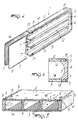
- figure 1 is a schematic view of the separator structure according to the invention;
- figure 2 is a transverse sectional view taken along the lines I-I of figure 1;
- figure 3 is a schematic view of the application of the separators to the frames of weaving looms;
- figure 4 is a schematic partially exploded perspective view of the separator structure according to the invention;
- figure 5 is a partially cutout perspective view of the plate-like elements;
- figure 6 is a transverse sectional view taken along the line VI-VI of figure 5.
- With reference to the above described figures, the separator structure for guiding weaving loom frames, according to the invention, is generally indicated by the reference numeral 1 and comprises a pair of plate-
like elements - The plate-
like elements - Said plate-
like elements reference numeral 4. - Dividing
elements 7 may furthermore be advantageously provided; said elements divide the open cavity defined by theborder 4 and by the plate-like components - Said dividing
elements 7 taper along their longitudinal extension to facilitate their separation from the mold, and their transverse cross sections defineconcave surfaces - As is evident from the drawing, the
border portion 4 only affects a part of the plate-like elements, so that said plate-like elements are mutually disengaged for a certain part of their longitudinal extension, i.e. starting from theedge 8, and define in practice the region for coupling to the frames of the weaving loom, which are indicated by thereference numeral 10 in figure 3. - Mutual coupling means are provided to stably connect the plate-like elements and the
border 4, and according to what is illustrated in the drawings they are constituted by abevel 5 which is provided on the outer edge of the plate-like elements and prevents the uncoupling of the plate-like elements by mutual spacing, while the divarication of theborder 4 is prevented by channels orgrooves 14 defined on the opposite faces of the plate-like elements - Through
holes 13 may furthermore be provided on the plate-like elements to increase the locking of the border proximate to its free ends; said holes provide firm locking points as they are filled by the plastic material. - A series of holes may furthermore be provided, for example instead of the
grooves 14, affecting the periphery of the plate-like elements at region affected by the border so that the introduction of the plastic material therein constitutes a divarication-preventing element. - As previously mentioned, the
border portion 4 and the dividingelements 7 are provided by means of a molding of plastic material, and the plate-like elements must therefore be positioned precisely in the molds; two holes, indicated by thereference numeral 6, are provided for this purpose and are engaged by centering elements constituted by pins or dowels correspondingly provided in said mold. - The use of the channels or
grooves 14 on the plate-like elements holes 13 on the plate-like elements - Said dividing
elements 7, besides giving further stability to the separator structure by virtue of the adhesion of the injection-molded plastic material to the grooved surface of the plate-like elements, provide a simplified and effective means for reducing the noise produced by mutual impacts during the movement of the frames without having to introduce sound-absorbing material, thus contributing to a further reduction and simplification of the manufacturing steps. - From what has been described above it can thus be seen that the invention achieves the intended aim and objects, and in particular the fact is stressed that a separator is provided in which the plate-like elements are obtained with a plastic lamination, therefore with a highly wear-resistant material, and that the guiding body is delimited by the border which affects the periphery and is connected to the dividing elements, which have a very small cross section, with the consequent advantage of obtaining a separator having a very low weight.
- Another important aspect resides in the fact that the coupling between the plate-like elements and the border is not provided by glueing but by molding the border directly on the plate-like elements, which are correctly positioned inside the molds.
- Where technical features mentioned in any claim are followed by reference signs, those reference signs have been included for the sole purpose of increasing the intelligibility of the claims and accordingly such reference signs do not have any limiting effect on the scope of each element identified by way of example by such reference signs.
Claims (11)
- Separator structure for guiding weaving loom heddle frames, comprising a pair of plate-like elements (2, 3) characterized in that said plate-like elements (2, 3), parallel and spaced-apart, are joined by at least one separate border element (4) affecting a portion of a periphery defined by said plate-like elements (2, 3), coupling means (5, 13, 14) being furthermore provided to stably couple said plate-like elements (2, 3) and said border element (4).
- Separator structure according to claim 1, characterized in that said plate-like elements (2, 3) define, in co-operation with said border element (4), an open cavity in which means (7) are provided to divide said cavity into a plurality of reduced-volume chambers.
- Separator structure according to claim 2, characterized in that said means adapted to divide said cavity into a plurality of chambers are constituted by dividing elements (7) which extend longitudinally with respect to the longitudinal extension of said plate-like elements (2, 3).
- Separator structure, according to claim 2, characterized in that said border element (4) is concave on its inner side, said dividing elements (7) having concave lateral faces (11, 12).
- Separator structure according to claim 2, characterized in that said means to divide said cavity comprise dividing elements (7) taper along their longitudinal extension.
- Separator structure, according to claim 1, characterized in that said means for mutually coupling said plate-like elements (2, 3) and said border element (4) have interlocking means (13, 14), adapted to prevent relative movement of said plate-like elements (2, 3) with respect to said border element (4) in planes which are essentially parallel to the planes in which said plate-like elements are arranged, and means (5) adapted to prevent movement of said plate-like elements (2, 3) along a direction which is essentially perpendicular to the plane in which said plate-like elements are arranged.
- Separator structure according to claim 6, characterized in that said means adapted to prevent movement of said plate-like elements (2, 3) along planes essentially parallel to the planes in which said plate-like elements are arranged are constituted by channels (14) provided on opposite faces of said plate-like elements and engaged by complementary protrusions provided on said border element (4) and on said dividing elements (7).
- Separator structure, according to claim 6, characterized in that said means adapted to prevent the movement of said plate-like elements (2, 3) in planes essentially parallel to the planes in which said plate-like elements are arranged comprise holes (13) which are defined at least along a portion of the periphery of said plate-like elements and are engaged by protrusions provided on said border element (4).
- Separator structure, according to claim 6, characterized in that said means adapted to prevent the movement of said plate-like elements (2, 3) relatively to said border element (4) along a direction substantially perpendicular to the planes in which said plate-like elements are arranged are constituted by a lip (9) defined by said border element (4) and engaging a bevel portion (5) defined perimetrally by said plate-like elements.
- Separator structure, according to claim 2, characterized in that said border element (4) and said means (7) to divide said cavity are obtained by molding plastic material on said plate-like elements (2, 3) arranged in a mold.
- Separator structure according to claim 1, characterized in that it comprises centering holes defined on said plate-like elements (2, 3) to act as locator elements in said mold.
Applications Claiming Priority (4)
| Application Number | Priority Date | Filing Date | Title |
|---|---|---|---|
| IT2045988 | 1988-05-05 | ||
| IT20459/88A IT1217495B (en) | 1988-05-05 | 1988-05-05 | Loom heald frames sepg. guide |
| IT8822581A IT1229807B (en) | 1988-11-10 | 1988-11-10 | Loom heald frames sepg. guide |
| IT2258188 | 1988-11-10 |
Publications (2)
| Publication Number | Publication Date |
|---|---|
| EP0341526A1 EP0341526A1 (en) | 1989-11-15 |
| EP0341526B1 true EP0341526B1 (en) | 1993-03-10 |
Family
ID=26327540
Family Applications (1)
| Application Number | Title | Priority Date | Filing Date |
|---|---|---|---|
| EP89107844A Expired - Lifetime EP0341526B1 (en) | 1988-05-05 | 1989-04-29 | Separator structure for guiding weaving loom frames |
Country Status (4)
| Country | Link |
|---|---|
| US (1) | US4966203A (en) |
| EP (1) | EP0341526B1 (en) |
| JP (1) | JPH0247331A (en) |
| DE (1) | DE68905227T2 (en) |
Families Citing this family (2)
| Publication number | Priority date | Publication date | Assignee | Title |
|---|---|---|---|---|
| US5275210A (en) * | 1992-08-11 | 1994-01-04 | Steel Heddle Mfg. Co. | Nose guide for a heddle frame |
| US11629649B2 (en) | 2020-05-11 | 2023-04-18 | Raytheon Technologies Corporation | Gas turbine engine with speed sensor |
Family Cites Families (19)
| Publication number | Priority date | Publication date | Assignee | Title |
|---|---|---|---|---|
| US3250421A (en) * | 1963-05-13 | 1966-05-10 | Braun Bernard | Container for transporting goods in commerce |
| US3283915A (en) * | 1964-03-31 | 1966-11-08 | Maslow Louis | Tray or rack assembly |
| CH439166A (en) * | 1966-04-04 | 1967-06-30 | Grob & Co Ag | Lockable guide for shaft rods of heald frames |
| US3417787A (en) * | 1966-09-07 | 1968-12-24 | Steel Heddle Mfg Co | Loom harness |
| US3410391A (en) * | 1967-07-06 | 1968-11-12 | Hanson Whitney Company | Storage and shipping container |
| CH577574A5 (en) * | 1974-04-18 | 1976-07-15 | Grob & Co Ag | |
| US3901282A (en) * | 1974-05-22 | 1975-08-26 | Steel Heddle Mfg Co | Loom harness |
| US4204045A (en) * | 1978-02-15 | 1980-05-20 | Orion-Yhtyma Oy | Device for examining microorganisms |
| JPS5533913U (en) * | 1978-08-24 | 1980-03-05 | ||
| JPS5540216U (en) * | 1978-09-06 | 1980-03-14 | ||
| JPS605010Y2 (en) * | 1980-07-14 | 1985-02-15 | 株式会社丸山製作所 | Information board for heddle frame |
| EP0053577A1 (en) * | 1980-12-03 | 1982-06-09 | Felix Kappler | Arrangement for the automatic closing of a box |
| US4372445A (en) * | 1981-02-19 | 1983-02-08 | Keffeler Paul J | Medication dispenser |
| DE3131375C2 (en) * | 1981-08-07 | 1983-06-16 | Gebrüder Schmeing, 4280 Borken | "Guide attachment for the shaft rods in heald frames" |
| JPS6082471U (en) * | 1983-11-09 | 1985-06-07 | 株式会社丸山製作所 | Information board for heddle frame |
| US4572242A (en) * | 1983-11-09 | 1986-02-25 | Maruyama Mfg. Co., Ltd. | Heald frame assembly |
| US4565223A (en) * | 1984-10-29 | 1986-01-21 | Steel Heddle Mfg. Co. | Stabilized nose guide |
| US4741441A (en) * | 1987-07-13 | 1988-05-03 | Keffeler Paul J | Medication dispenser with removable liner and sealed compartments |
| EP0303745A1 (en) * | 1987-08-20 | 1989-02-22 | Factshore Ltd | A bean-bag supported lap tray |
-
1989
- 1989-04-29 EP EP89107844A patent/EP0341526B1/en not_active Expired - Lifetime
- 1989-04-29 DE DE8989107844T patent/DE68905227T2/en not_active Expired - Fee Related
- 1989-05-02 US US07/346,199 patent/US4966203A/en not_active Expired - Fee Related
- 1989-05-02 JP JP1112290A patent/JPH0247331A/en active Granted
Also Published As
| Publication number | Publication date |
|---|---|
| JPH0247331A (en) | 1990-02-16 |
| JPH0362814B2 (en) | 1991-09-27 |
| DE68905227D1 (en) | 1993-04-15 |
| DE68905227T2 (en) | 1993-06-17 |
| US4966203A (en) | 1990-10-30 |
| EP0341526A1 (en) | 1989-11-15 |
Similar Documents
| Publication | Publication Date | Title |
|---|---|---|
| DK9500332U3 (en) | Corner assembly between the end portions of two board-like items | |
| US4200479A (en) | Method of making a hockey stick | |
| US4159114A (en) | Ice hockey stick | |
| US4290212A (en) | Wooden shoe including hinge | |
| US8567794B2 (en) | Frame structure for skates | |
| US4684130A (en) | Ice hockey stick | |
| US3998457A (en) | Tennis racket | |
| JPH04505409A (en) | plastic shell skis | |
| EP0341526B1 (en) | Separator structure for guiding weaving loom frames | |
| US6446676B1 (en) | Multicomponent cross-piece for low-noise heddle frames in weaving looms | |
| US5249819A (en) | Ski having a hollow body of uniform width | |
| JPH03501457A (en) | skiing | |
| US4369970A (en) | Hockey stick and method of manufacturing the same | |
| US3918731A (en) | Cross-country ski | |
| US9802106B2 (en) | Board sports structural element | |
| US3700252A (en) | Metal edge members for skis having varied lengthwise stress-strain ratio and skis including such members | |
| US5058356A (en) | Decorative structure | |
| US2178588A (en) | Racket | |
| US2260218A (en) | Hockey stick | |
| US4340378A (en) | V-Block component and belt | |
| KR102357332B1 (en) | Assembled structure of door leaf made | |
| FI67484B (en) | SKRIDSKO AVSEDD ATT FAESTAS VID SULAN AV ETT SKODON OMFATTANDEETT I EN PLASTSTOMME FAEST LAONGSTRAECKT STAOLBLAD | |
| KR950001056A (en) | Manufacturing method of wood door and its structure | |
| KR840000356Y1 (en) | Cotton Fhenol Resin Shottle Block | |
| US5333890A (en) | Process of manufacturing a ski and a ski produced by the process |
Legal Events
| Date | Code | Title | Description |
|---|---|---|---|
| PUAI | Public reference made under article 153(3) epc to a published international application that has entered the european phase |
Free format text: ORIGINAL CODE: 0009012 |
|
| AK | Designated contracting states |
Kind code of ref document: A1 Designated state(s): BE CH DE ES FR LI |
|
| RAP1 | Party data changed (applicant data changed or rights of an application transferred) |
Owner name: LAMIFLEX S.P.A. |
|
| RIN1 | Information on inventor provided before grant (corrected) |
Inventor name: CARRARA, ELIO |
|
| 17P | Request for examination filed |
Effective date: 19891230 |
|
| 17Q | First examination report despatched |
Effective date: 19910710 |
|
| GRAA | (expected) grant |
Free format text: ORIGINAL CODE: 0009210 |
|
| AK | Designated contracting states |
Kind code of ref document: B1 Designated state(s): BE CH DE ES FR LI |
|
| PG25 | Lapsed in a contracting state [announced via postgrant information from national office to epo] |
Ref country code: ES Free format text: THE PATENT HAS BEEN ANNULLED BY A DECISION OF A NATIONAL AUTHORITY Effective date: 19930310 |
|
| ET | Fr: translation filed | ||
| REF | Corresponds to: |
Ref document number: 68905227 Country of ref document: DE Date of ref document: 19930415 |
|
| PLBE | No opposition filed within time limit |
Free format text: ORIGINAL CODE: 0009261 |
|
| STAA | Information on the status of an ep patent application or granted ep patent |
Free format text: STATUS: NO OPPOSITION FILED WITHIN TIME LIMIT |
|
| 26N | No opposition filed | ||
| PGFP | Annual fee paid to national office [announced via postgrant information from national office to epo] |
Ref country code: BE Payment date: 19950412 Year of fee payment: 7 |
|
| PGFP | Annual fee paid to national office [announced via postgrant information from national office to epo] |
Ref country code: CH Payment date: 19950427 Year of fee payment: 7 |
|
| PGFP | Annual fee paid to national office [announced via postgrant information from national office to epo] |
Ref country code: FR Payment date: 19950428 Year of fee payment: 7 |
|
| PGFP | Annual fee paid to national office [announced via postgrant information from national office to epo] |
Ref country code: DE Payment date: 19950509 Year of fee payment: 7 |
|
| PG25 | Lapsed in a contracting state [announced via postgrant information from national office to epo] |
Ref country code: LI Effective date: 19960430 Ref country code: CH Effective date: 19960430 Ref country code: BE Effective date: 19960430 |
|
| BERE | Be: lapsed |
Owner name: LAMIFLEX S.P.A. Effective date: 19960430 |
|
| REG | Reference to a national code |
Ref country code: CH Ref legal event code: PL |
|
| PG25 | Lapsed in a contracting state [announced via postgrant information from national office to epo] |
Ref country code: FR Effective date: 19961227 |
|
| PG25 | Lapsed in a contracting state [announced via postgrant information from national office to epo] |
Ref country code: DE Effective date: 19970101 |
|
| REG | Reference to a national code |
Ref country code: FR Ref legal event code: ST |