EP0341459A2 - Agricultural tractor having soil-working implements attached thereto - Google Patents
Agricultural tractor having soil-working implements attached thereto Download PDFInfo
- Publication number
- EP0341459A2 EP0341459A2 EP19890106977 EP89106977A EP0341459A2 EP 0341459 A2 EP0341459 A2 EP 0341459A2 EP 19890106977 EP19890106977 EP 19890106977 EP 89106977 A EP89106977 A EP 89106977A EP 0341459 A2 EP0341459 A2 EP 0341459A2
- Authority
- EP
- European Patent Office
- Prior art keywords
- tractor
- force
- attachment
- vehicle
- vibration damping
- Prior art date
- Legal status (The legal status is an assumption and is not a legal conclusion. Google has not performed a legal analysis and makes no representation as to the accuracy of the status listed.)
- Granted
Links
Images


Classifications
-
- A—HUMAN NECESSITIES
- A01—AGRICULTURE; FORESTRY; ANIMAL HUSBANDRY; HUNTING; TRAPPING; FISHING
- A01B—SOIL WORKING IN AGRICULTURE OR FORESTRY; PARTS, DETAILS, OR ACCESSORIES OF AGRICULTURAL MACHINES OR IMPLEMENTS, IN GENERAL
- A01B63/00—Lifting or adjusting devices or arrangements for agricultural machines or implements
- A01B63/02—Lifting or adjusting devices or arrangements for agricultural machines or implements for implements mounted on tractors
- A01B63/10—Lifting or adjusting devices or arrangements for agricultural machines or implements for implements mounted on tractors operated by hydraulic or pneumatic means
- A01B63/1006—Lifting or adjusting devices or arrangements for agricultural machines or implements for implements mounted on tractors operated by hydraulic or pneumatic means the hydraulic or pneumatic means structurally belonging to the tractor
Definitions
- the invention relates to an agricultural tractor, in particular a tractor or construction vehicle, with an attachment coupled via an attachment and with a device for actively damping pitching vibrations of the vehicle.
- Such a vehicle is already known from DE-OS 34 46 811, in which a plow is articulated on a tractor via a three-point linkage and with the aid of the electro-hydraulic control device for plow adjustment, active vibration damping of the implement can be reached in its excavated position.
- active vibration damping of the implement can be reached in its excavated position.
- the force control loop and its associated force sensor are preferably used for such vibration damping.
- horizontal forces determined by the force sensor in the handlebars can change if a cornering linkage connected to the handlebars transfers part of the horizontal forces to the housing of the tractor when cornering and / or when the attachment swings sideways, thereby impairing the accuracy of the measurement results.
- tractor in which pulling chains are used instead of rigid rods as side guide linkages. It is also common for some types of tractor to provide additional housing-fixed support surfaces or cams for this side guide, which limit a lateral breakout of the handlebars.
- EP-Al-0 033 923 discloses a tractor with an electro-hydraulic control device for plow adjustment, in which the lower link is mounted on the housing of the tractor with the aid of a force measuring bolt.
- the control device is operated with the sum of both force measuring pin signals.
- active vibration damping is not provided here. Unfavorable conditions for determining the force can occur particularly when the articulation points of the two lower links on the housing of the tractor are relatively close to each other and the lower links projecting V-shaped are supported on the tractor frame via oblique side guide rods, so that, for example, when cornering, part of the Horizontal forces are transferred to the tractor housing.
- the agricultural tractor according to the invention with the characterizing features of the main claim has the advantage that the function of the active vibration damping during transport of the vehicle with the attached implement remains functional and safe even when cornering and / or lateral oscillation of the implement.
- the actuating movements on the hoist can also be kept as small as possible, which also leads to less stress on the components.
- the device can only be implemented in the electronics with relatively little effort.
- This drop in the sum signal of the force sensors which is independent of the type of cornering means such as rigid rod, pull chain or e.g. Support surfaces fixed to the housing no longer have a disruptive effect on vibration damping.
- This function is also important because the higher the average excavation height, the greater the drop in the sum signal.
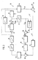
- a tractor 10 is shown as an agricultural tractor that can be used with a rear-mounted attachment 11, which can be designed, for example, as a plow.
- the attachment 11 is adjustable in height in a manner known per se via an attachment device, which can be designed as a three-point linkage 12, with the upper link 13 and lower link 14 directed.
- an attachment device which can be designed as a three-point linkage 12, with the upper link 13 and lower link 14 directed.
- To adjust the attachment 11 engages on the lower link 14, a hydraulic power lift 15, which is switched into a hydraulic circuit with a pump 16 and an electro-hydraulic control valve 17 GE.
- the control valve 17 is controlled by an electronic control unit 18 which, like the control valve 17 and the three-point linkage 12 with the power lift 15, is part of an electrohydraulic lifting mechanism control device 19.
- an attachment 11 designed as a plow can not only be operated in operating positions in various control types, but the attachment 11 can be moved out of the operating position into the illustrated excavation position, in which it has a limited amplitude around a middle excavation position can be moved.
- the control device 19 controls the movements of the implement 11 used as the absorber mass such that the vibrations of the tractor 10, in particular its pitching movements about its horizontally lying oscillation axis 21, are actively damped.
- the control device 19 processes the actual values from a plurality of sensors, for which purpose the lower link 14 is articulated on the tractor 10 via a force measuring pin 22 known per se.
- the force measuring pin 22 determines the horizontal force transmitted by the lower link 14 and reports proportional electrical signals to the electronic control unit 18.
- a position sensor 23 is provided, which signals the control unit 18 as a function of the position of the attachment 11 relative to the tractor 10.
- FIG. 2 shows a part of the tractor 10 according to FIG. 1 in a bottom view, in which the double arrangement of the lower link 14 is clearly visible.
- the double arrangement is provided with the same reference number, but with the index '.
- the two lower links 14, 14 ' are pivotally mounted on their respective force measuring bolts 22, 22' on a housing 24 of the tractor 10.
- each lower link 14, 14 ' is supported by a side guide rod 26, 26' on the rear axle 27 of the tractor 10 fixed to the housing.
- the side guide rods 26, 26 ' are in their coupling points 28, 28' on the rear axle 27 each with an elongated hole, whereby each lower link 14, 14 'at its coupling point 25 or 25' a maximum lateral movement by a distance 29 at the coupling points 25 can perform.
- FIG. 3 shows a block diagram in a simplified representation of a device 30 for dynamically stabilizing the movement of the vehicle 10, ie for active vibration damping, as is integrated in the hoist control device 19 according to FIG. 1.
- the system attachment 11, power lift 15 forms together with the tractor 10 an oscillatable unit which can be excited to vibrate by impacts on the tractor 10 from the outside.
- the pitch angle of the tractor 10 about its oscillation axis 21 is changed via various kinematic factors 31 and returned to a first summing point 32.
- a static force F stat originating from the mass of the implement 11 is supplied, so that the entire force F acts on the force measuring bolt 22.
- the force measuring pin 22 of the hoist control device 19 With the force measuring pin 22 of the hoist control device 19, the signal for the movement of the attachment 11 serving as absorber mass is thus obtained at the same time.
- the force measuring pin 22 supplies an electrical voltage which is proportional to the magnitude of the respective force, in particular to the horizontal force transmitted by lower link 14.
- the dynamic and static components are then separated from one another, so that an electrical output signal is obtained at a third summation point 35, which corresponds to the dynamic component and is therefore proportional to the force F dyn , which is mainly caused by impacts on the tractor 10, for example as a result of uneven roads.
- These signals which are proportional to the dynamic force component, serve as an input variable for the force control circuits 36 and are input to a proportional controller 37.
- the output signal of the first controller 37 is led via a dead zone comparator 38 to a fourth summing point 39, at which the output signal of a second controller 41 is additionally present in a position control loop 42.
- the output signal from the fourth sum point 39 is passed through a switching device 43 for dead zone comparison and acts on the control valve 17, which in turn influences the power lift 15.
- the position-dependent output signal from the power lift 15 acts on the one hand via the first summation point 32 on the attachment 11 and on the other hand on the position sensor 44.
- the electrical output signal of the position sensor 44 is compared on the one hand at a fifth summation point 45 with a position setpoint 46 and the resulting control deviation of the position dem second controller 41 entered.
- the actual position value acts on the low-pass filter 34 via an active connection 47 in such a way that its time constant changes as a function of this position influence, as will be described in more detail below.
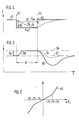
- FIG. 4 shows the signal curve of the force F when the tractor 10 is cornering in vibration damping operation
- FIG. 5 records the associated signal curve of the excavation height or the position over time.
- a solid first line 51 shows the course of the actual value of the force F during cornering.
- the actual value of the total force F measured by the force measuring pin 22 suddenly collapses because part of the horizontal forces is absorbed by a side guide rod 26, 26 '. This drop in force is maintained for the duration of the cornering, this duration being of the order of 3 to 6 seconds, for example can lie.
- the side guide rod 26, 26 ' is relieved again, so that the actual force value returns to its old value.
- the desired force value F s formed in the low-pass filter 34 changes only slowly at its output.
- the signal curve of this force setpoint is shown in FIG. 4 by a second dashed line 54.
- the controller 37 in the force control circuit 36 reacts to this control difference 55 occurring at the start of the curve, which results from the course of the curves 51 and 54, by lifting the attachment 11 until it stops.
- FIG. 5 shows in more detail, this stop is reached when the actual position value corresponds to a position of the upper end position, as shown in FIG. 5 by the boundary line 56.
- the attachment 11 was lifted out of a middle excavation position 57, about which the attachment 11 can swing to both sides in the vibration damping mode.
- the distance between the middle excavation position 57 and the upper boundary line 56 can amount to approximately 3% of the total excavation height.
- the time constant T also increases.
- the time constant T of the low-pass filter 34 is also very large. With a decreasing position from 56 to 57, the time constant T also decreases again.
- the device 30 can therefore perform the function of active vibration damping when cornering the tractor 10 and / or when the attachment 11 swings sideways considerably more effectively and safely.
- the lifting height of the hoist can be used more optimally, since the positioning movements during vibration damping are kept smaller overall.
- the second controller 41 is specially designed in the position control loop 42.
- the position setpoint 46 in vibration damping operation is predetermined by the size of the middle excavation position 57.
- the current position of the hoist as it is tapped at the output of the position sensor 44 serves as the actual position value.
- FIG. 6 shows in more detail, in which the output variable of the second controller 41 is shown as a function of the entered control difference of the position, the second, proportionally operating controller 41 has a kinked characteristic curve 65.
- the characteristic curve 65 of the controller 41 is selected so that the gain in the subordinate position control loop 42 increases significantly when the actual position value moves more than 2% away from the middle excavation position 57, the total stroke of the hoist being equated with 100%. In this way, breaking out of the actual position value is made even more difficult. In normal operation, if the control deviation of the position remains below 2%, the position gain is relatively small, so that the force control circuit 36, which is decisive for the vibration damping, remains correspondingly sensitive.
- the formation of the second controller 41 with a kinked characteristic curve 65 can also be used independently of the variable time constant in the force control circuit 36 in order to positively influence the active vibration damping when cornering.
- the combination of both measures allows a particularly powerful vibration damping on the tractor 10 when cornering and comparable vibration cases.
- the device is not limited to the tractor type shown, in which the side guide linkage is designed as rigid rods and can transmit tensile and compressive forces.
- the same drop in the sum signal also occurs if pull chains are used instead of the rigid bars for the lateral guidance.
- support surfaces or cams are provided for lateral guidance, which limit the lateral movement of the handlebars; all of these means are referred to as lateral guide members.
- the force measuring bolts can also be further apart than is shown in FIG. 2.
- the handlebars can also run parallel to each other and e.g. be articulated on the rear axle.
- the device can be used particularly advantageously with force measuring bolts, it would also be possible to use other force sensors instead, in which similar signal curves occur with a drop in the sum signal when the tractor is cornering and / or the implement is swinging sideways.
Landscapes
- Life Sciences & Earth Sciences (AREA)
- Engineering & Computer Science (AREA)
- Mechanical Engineering (AREA)
- Soil Sciences (AREA)
- Environmental Sciences (AREA)
- Lifting Devices For Agricultural Implements (AREA)
Abstract
Es wird ein Traktor (10) mit angelenktem Anbaugerät (11) vorgeschlagen, bei dem die Funktion der aktiven Schwingungsdämpfung in Aushubstellung mit Hilfe der elektrohydraulischen Hubwerksregeleinrichtung (19) bei Kurvenfahrten wirksamer und sicherer ausführbar ist. Bei der Kurvenfahrt von Seitenführungsgliedern (26, 26′) auf das Traktorgehäuse (24) übertragene Kräfte führen zu kurzzeitigen Signaleinbrüchen in den die Unterlenker (14, 14′) lagernden Kraftmeßbolzen (22, 22′), welche die horizontalen Kräfte messen. In dem für die Schwingungsdämpfung maßgebenden Kraftregelkreis (36) liegt ein zur Ermittlung des dynamischen Kraftanteils dienendes Tiefpaßfilter (34), dessen Zeitkonstante (T) abhängig vom Lage-Istwert so verändert wird, daß am Kurvenende (53) kleinere Regelabweichungen der Kraft und damit kleinere Hubwerksamplituden um die mittlere Aushubstellung eintreten, so daß die aktive Schwingungsdämpfung bei Kurvenfahrt kaum beeinträchtigt ist. 
Description
Die Erfindung geht aus von einer landwirtschaftlich nutzbaren Zugmaschine, insbesondere Traktor oder Baumaschinen-Fahrzeug, mit über eine Anbauvorrichtung angekoppeltem Anbaugerät und mit einer Einrichtung zur aktiven Dämpfung von Nickschwingungen des Fahrzeugs.The invention relates to an agricultural tractor, in particular a tractor or construction vehicle, with an attachment coupled via an attachment and with a device for actively damping pitching vibrations of the vehicle.
Es ist schon ein solches Fahrzeug aus der DE-OS 34 46 811 bekannt, bei dem an einem Traktor über ein Dreipunktgestänge ein Pflug angelenkt ist und mit Hilfe der elektrohydraulischen Regeleinrichtung zur Pflugverstellung eine aktive Schwingungsdämpfung des Anbaugeräts in dessen Aushubstellung erreichbar ist. Mit einem solchen System zur dynamischen Stabilisierung der Bewegungen des Fahrzeugs können dessen Nickschwingungen reduziert werden, so daß bei ausgehobenem Anbaugerät hohe Transportgeschwindigkeiten und eine große Lenksicherheit möglich sind. Für eine derartige Schwingungsdämpfung werden bevorzugt der Kraftregelkreis und sein zugehöriger Kraftsensor eingesetzt. Bei dieser bauweise können nun ungünstige Betriebsbedingungen auftreten, bei denen sich durch eine ungenaue Signalermittlung Einflüsse einstellen, welche die Güte der Schwingungsdämpfung beeinträchtigen und auch zu vergrößerter Bewegungsamplitude des An baugeräts führen können. So können vom Kraftsensor im Lenker ermittelte Horizontalkräfte sich verändern, wenn bei Kurvenfahrt und/oder bei seitlichem Pendeln des Anbaugeräts ein mit dem Lenker verbundenes Seitenführungsgestänge einen Teil der horizontalen Kräfte auf das Gehäuse des Traktors übertragen und damit die Genauigkeit der Meßergebnisse beeinträchtigen. Dabei gibt es auch Schleppertypen, bei denen als Seitenführungsgestänge nicht starre Stangen, sondern auch Zugketten verwendet werden. Auch ist es bei manchen Schleppertypen üblich, für diese Seitenführung zusätzliche gehäusefeste Abstützflächen oder Nocken vorzusehen, die ein seitliches Ausbrechen der Lenker begrenzen.Such a vehicle is already known from DE-OS 34 46 811, in which a plow is articulated on a tractor via a three-point linkage and with the aid of the electro-hydraulic control device for plow adjustment, active vibration damping of the implement can be reached in its excavated position. With such a system for the dynamic stabilization of the movements of the vehicle, its pitching vibrations can be reduced, so that high transport speeds and a high degree of steering safety are possible when the attachment is raised. The force control loop and its associated force sensor are preferably used for such vibration damping. With this design, unfavorable operating conditions can now occur, in which influences arise due to inaccurate signal determination, which impair the quality of the vibration damping and also to an increased movement amplitude of the type can lead construction equipment. For example, horizontal forces determined by the force sensor in the handlebars can change if a cornering linkage connected to the handlebars transfers part of the horizontal forces to the housing of the tractor when cornering and / or when the attachment swings sideways, thereby impairing the accuracy of the measurement results. There are also types of tractor in which pulling chains are used instead of rigid rods as side guide linkages. It is also common for some types of tractor to provide additional housing-fixed support surfaces or cams for this side guide, which limit a lateral breakout of the handlebars.
Ferner ist aus der DE-OS 33 46 892 ein Fahrzeug mit einem gelenkig befestigten Anbaugerät bekannt, bei der ebenfalls mit Hilfe der elektrohydraulischen Hubwerks-Regeleinrichtung die Nickschwingungen des Traktors gedämpft werden sollen. Eine Dämpfung soll hier primär dadurch erreicht werden, daß das Anbaugerät in vertikaler Richtung räumlich annähernd ruhig gehalten wird. Zum Einfluß und zur Beherrschung von Querschwingungen des Pfluges relativ zum Traktor, werden bei diesem Fahrzeug keine Hinweise gegeben.Furthermore, from DE-OS 33 46 892 a vehicle with an articulated attachment is known, in which the pitching vibrations of the tractor are also to be damped with the aid of the electro-hydraulic hoist control device. Attenuation is to be achieved primarily by keeping the attachment almost spatially calm in the vertical direction. No information is given on this vehicle regarding the influence and control of transverse vibrations of the plow relative to the tractor.
Ferner ist aus der EP-Al-0 033 923 ein Traktor mit einer elektrohydraulischen Regeleinrichtung zur Pflugverstellung bekannt, bei welcher der Unterlenker mit Hilfe eines Kraftmeßbolzens am Gehäuse des Traktors gelagert ist. In der Regel wird mit der Summe aus beiden Kraftmeßbolzen-Signalen die Regeleinrichtung betrieben. Eine aktive Schwingungsdämpfung ist hier jedoch nicht vorgesehen. Ungünstige Verhältnisse für die Kraftermittlung können besonders dann auftreten, wenn die Anlenkpunkte der beiden Unterlenker am Gehäuse des Traktors relativ nahe beieinander liegen und die nach hinten V-förmig auskragenden Unterlenker über schräg verlaufende Seitenführungsgestänge am Traktorrahmen abgestützt sind, so daß z.B. bei Kurvenfahrten ein Teil der Horizontalkräfte auf das Traktorgehäuse übertragen wird.Furthermore, EP-Al-0 033 923 discloses a tractor with an electro-hydraulic control device for plow adjustment, in which the lower link is mounted on the housing of the tractor with the aid of a force measuring bolt. As a rule, the control device is operated with the sum of both force measuring pin signals. However, active vibration damping is not provided here. Unfavorable conditions for determining the force can occur particularly when the articulation points of the two lower links on the housing of the tractor are relatively close to each other and the lower links projecting V-shaped are supported on the tractor frame via oblique side guide rods, so that, for example, when cornering, part of the Horizontal forces are transferred to the tractor housing.
Die erfindungsgemäße landwirtschaftlich nutzbare Zugmaschine mit den kennzeichnenden Merkmalen des Hauptanspruchs hat demgegenüber den Vorteil, daß die Funktion der aktiven Schwingungsdämpfung bei Transportfahrt des Fahrzeugs mit ausgehobenem Anbaugerät auch bei einer Kurvenfahrt und/oder seitlichem Pendeln des Anbaugeräts funktionsfähig und sicher bleibt. Dies geschieht in einfacher und vorteilhafter Weise dadurch, daß das zur aktiven Dämpfung verwendete Signal im Kraftregelkreis, das bei Kurvenfahrt einen Einbruch erleidet, in seinem Einfluß wenigstens kurzzeitig überbrückt wird. Im Interesse einer optimalen Ausnutzung der Aushubhöhe können ferner die Stellbewegungen am Hubwerk möglichst klein gehalten werden, was auch zu geringerer Belastung der Bauteile führt. Ferner läßt sich die Einrichtung mit relativ geringem Aufwand nur in der Elektronik realisieren. Dieser Einbruch des Summensignals der Kraftsensoren, der unabhängig von der Art des Seitenführungsmittel wie starre Stange, Zugkette oder z.B. gehäusefeste Abstützflächen auftritt, hat keinen störenden Einfluß mehr auf die Schwingungsdämpfung. Diese Funktion ist auch deswegen wesentlich, weil der einbruch des Summensignals umso größer ist, je höher die mittlere Aushubhöhe gewählt wird.The agricultural tractor according to the invention with the characterizing features of the main claim has the advantage that the function of the active vibration damping during transport of the vehicle with the attached implement remains functional and safe even when cornering and / or lateral oscillation of the implement. This takes place in a simple and advantageous manner in that the influence of the signal used for active damping in the force control loop, which suffers a break when cornering, is at least briefly bridged. In the interest of optimal utilization of the excavation height, the actuating movements on the hoist can also be kept as small as possible, which also leads to less stress on the components. Furthermore, the device can only be implemented in the electronics with relatively little effort. This drop in the sum signal of the force sensors, which is independent of the type of cornering means such as rigid rod, pull chain or e.g. Support surfaces fixed to the housing no longer have a disruptive effect on vibration damping. This function is also important because the higher the average excavation height, the greater the drop in the sum signal.
Durch die in den Unteransprüchen aufgeführten Maßnahmen sind vorteilhafte Weiterbildungen und Verbesserungen der im Hauptanspruch angegebenen Zugmaschine möglich. Eine besonders einfache, kostengünstige und wirksam arbeitende Einrichtung wird möglich, wenn gemäß den Ansprüchen 2 und 3 das zum Ermitteln des dynamischen Kraftanteils verwendete Tiefpaßfilter so ausgebildet wird, daß seine Zeitkonstante abhängig von der Lage des Hubwerks verändert wird. Damit kann auch die Stellbewegung am Hubwerk möglichst klein gehalten werden, was einer optimalen Ausnutzung der Aushubhöhe zugute kommt. Weiterhin ist es besonders zweckmäßig, wenn die Einrichtung auf der Zugmaschine gemäß den Ansprüchen 4 und 5 ausgebildet wird, so daß der Einfluß des Lageregelkreises beim Überschreiten bestimmter Grenzwerte durch die Regelabweichung wesentlich verstärkt wird, was sich mit einem Regler mit geknickter Kennlinie besonders zweckmäßig realisieren läßt. Auch damit können störende Einflüsse bei Kurvenfahrt auf die aktive Schwingungsdämpfung wesentlich vermindert werden. Weitere besonders vorteilhafte Ausgestaltungen ergeben sich aus den Ansprüchen 6 bis 9, wobei es besonders vorteilhaft ist, die erforderlichen Funktionen gemäß Anspruch 9 in Digitaltechnik mit einem Mikroprozessor auszuführen. Nach den Ansprüchen 12 und 13 werden vorteilhafte Verfahren zu aktiven Schwingungsdämpfung bei Kurvenfahrten und vergleichbaren Einflüssen vorgeschlagen.Advantageous further developments and improvements of the tractor specified in the main claim are possible through the measures listed in the subclaims. A particularly simple, inexpensive and effective device is possible if, according to
Ein Ausführungsbeispiel der Erfindung ist in der Zeichnung dargestellt und in der nachfolgenden Beschreibung näher erläutert. Es zeigen die
Figur 1 einen Traktor mit angekoppeltem Anbaugerät in Aushubstellung und mit einer Einrichtung zur aktiven Schwingungsdämpfung bei Kurvenfahrt,Figur 2 eine teilweise Untersicht des Traktors nachFigur 1,Figur 3 ein Blockschaltbild für die Einrichtung zur Schwingungsdämpfung nachFigur 1 in vereinfachter Darstellung,- Figur 4 und 5 die Signalverläufe bei Kurvenfahrt im Schwingungsdämpfungsbetrieb und
- Figur 6 die Kennlinie des Reglers im Lageregelkreis.
- 1 shows a tractor with a coupled attachment in the excavation position and with a device for active vibration damping when cornering,
- FIG. 2 shows a partial bottom view of the tractor according to FIG. 1,
- FIG. 3 shows a block diagram for the device for vibration damping according to FIG. 1 in a simplified representation,
- Figures 4 and 5, the waveforms when cornering in vibration damping mode and
- Figure 6 shows the characteristic of the controller in the position control loop.
In der Figur 1 ist als landwirtschaftlich nutzbare Zugmaschine ein Traktor 10 mit einem heckseitig befestigten Anbaugerät 11 dargestellt, das beispielsweise als Pflug ausgebildet sein kann. Das Anbaugerät 11 ist dabei in an sich bekannter Weise über eine Anbauvorrichtung, die als Dreipunkt-Gestänge 12 ausgebildet sein kann, mit Oberlenker 13 und Unterlenker 14 am Traktor 10 höhenverstellbar an gelenkt. Zur Verstellung des Anbaugeräts 11 greift am Unterlenker 14 ein hydraulischer Kraftheber 15 an, der in einen hydraulischen Kreis mit einer Pumpe 16 und einem elektrohydraulischen Regelventil 17 ge schaltet ist. Das Regelventil 17 wird über ein elektronisches Steuergerät 18 angesteuert, das ebenso wie das Regelventil 17 und das Dreipunkt-Gestänge 12 mit dem Kraftheber 15 Teil einer elektrohydraulischen Hubwerksregeleinrichtung 19 ist. Mit Hilfe dieser Regeleinrichtung 19 kann beispielsweise ein als Pflug ausgebildetes Anbaugerät 11 nicht nur in Betriebsstellungen in verschiedenen Regelungsarten betrieben werden, sondern das Anbaugerät 11 aus der Betriebsstellung heraus in die gezeichnete Aushubstellung verfahren werden, in der es mit einer begrenzten Amplitude um eine mittlere Aushubstellung herum bewegt werden kann. Die Regeleinrichtung 19 steuert dabei die Bewegungen des als Tilgermasse verwendeten Anbaugeräts 11 derart, daß die Schwingungen des Traktors 10, insbesondere dessen Nickbewegungen um seine horizontal liegende Schwingachse 21 aktiv gedämpft werden. Die Regeleinrichtung 19 verarbeitet zu diesem Zweck die Istwerte von mehreren Sensoren, wozu einmal der Unterlenker 14 über einen an sich bekannten Kraftmeßbolzen 22 am Traktor 10 angelenkt ist. Der Kraftmeßbolzen 22 ermittelt die vom Unterlenker 14 übertragene Horizontalkraft und meldet dazu proportionale elektrische Signale an das elektronische Steuergerät 18. Ferner ist ein Lagesensor 23 vorgesehen, welchen von der Lage des Anbaugeräts 11 relativ zum Traktor 10 abhängige Signale an das Steuergerät 18 meldet.In FIG. 1, a
Die Figur 2 zeigt einen Teil des Traktors 10 nach Figur 1 in einer Untersicht, in der die doppelte Anordnung des Unterlenkers 14 deutlich sichtbar wird. Die doppelte Anordnung wird dabei mit dem gleichen Bezugszeichen, jedoch mit dem Index ′ versehen. Die beiden Unterlenker 14, 14′ sind über ihre jeweiligen Kraftmeßbolzen 22, 22′ an einem Gehäuse 24 des Traktors 10 schwenkbar gelagert. Die von den Kraftmeßbolzen 22, 22′ gebildeten Anlenkpunkte liegen, bedingt durch die Bauart des Traktorgehäuses 24, relativ nahe beieinander.FIG. 2 shows a part of the
Demgegenüber liegen die Kupplungspunkte 25, 25′ für das Anbaugerät 11 durch die auskragenden Unterlenker 14, 14′ weiter auseinander. Ferner ist jeder Unterlenker 14, 14′ durch eine Seitenführungsstange 26, 26′ an der gehäusefesten Hinterachse 27 des Traktors 10 abgestützt. Die Seitenführungsstangen 26, 26′ sind in ihren Ankoppelpunkten 28, 28′ auf der Hinterachse 27 jeweils mit einem Langloch versehen, wodurch jeder Unterlenker 14, 14′ an seinem Kupplungspunkt 25 bzw. 25′ eine maximale seitliche Bewegung um einen Abstand 29 an den Kupplungspunkten 25 ausführen kann.In contrast, the coupling points 25, 25 'for the
Die Figur 3 zeigt als Blockschaltbild in vereinfachter Darstellung eine Einrichtung 30 zur dynamischen Stabilisierung der Bewegung des Fahrzeugs 10, also zur aktiven Schwingungsdampfung, wie sie in der Hubwerksregeleinrichtung 19 nach Figur 1 integriert ist.FIG. 3 shows a block diagram in a simplified representation of a
Dabei bildet das System Anbaugerät 11, Kraftheber 15 zusammen mit dem Traktor 10 eine schwingungsfähige Einheit, die durch Stöße von außen auf den Traktor 10 zu Schwingungen angeregt werden kann. Der Nickwinkel des Traktors 10 um seine Schwingachse 21 wird über verschiedene kinematische Faktoren 31 verändert und auf einen ersten Summenpunkt 32 zurückgeführt. An einem zweiten Summenpunkt 33 zwischen Anbaugerät 11 und Traktor 10 wird eine von der Masse des Anbaugeräts 11 herrührende, statische Kraft Fstat zugeführt, so daß die gesamte Kraft F auf den Kraftmeßbolzen 22 einwirkt. Mit dem Kraftmeßbolzen 22 der Hubwerksregeleinrichtung 19 wird somit zugleich das Signal für die Bewegung des als Tilgermasse dienenden Anbaugeräts 11 gewonnen. Der Kraftmeßbolzen 22 liefert als Ausgangssignal eine elektrische Spannung, die proportional zur Größe der jeweiligen Kraft ist, insbesondere zu der von Unterlenker 14 übertragenen Horiztonalkraft. Mit Hilfe eines Tiefpaßfilters 34 werden anschließend die dynamischen und die statischen Anteile voneinander getrennt, so daß an einem dritten Summenpunkt 35 ein elektrisches Ausgangssignal gewonnen wird, das dem dynamischen Anteil entspricht und somit proportional zur Kraft Fdyn ist, die vor allem durch Stöße auf den Traktor 10 z.B. infolge von Straßenunebenheiten, hervorgerufen wird. Diese zum dynamischen Kraftanteil proportionalen Signale dienen als Eingangsgröße für den Kraftregelkreise 36 und werden einem Proportional-Regler 37 eingegeben. Das Ausgangssignal des ersten Reglers 37 wird über einen Totzonen-Vergleicher 38 zu einem vierten Summenpunkt 39 geführt, an dem zusätzlich das Ausgangssignal eines zweiten Reglers 41 in einem Lageregelkreis 42 anliegt. Das Ausgangssignal vom vierten Summenpunkt 39 wird über eine Schalteinrichtung 43 für Totzonen-Vergleich geführt und wirkt auf das Regelventil 17, das seinerseits den Kraftheber 15 beeinflußt. Das lageabhängige Ausgangssignal vom Kraftheber 15 wirkt einerseits über den ersten Summenpunkt 32 auf das Anbaugerät 11 und andererseits auf den Lagesensor 44. Das elektrische Ausgangssignal des Lagesensors 44 wird einerseits in einem fünften Summenpunkt 45 mit einem Lagesollwert 46 verglichen und die dabei gebildete Regelabweichung der Lage dem zweiten Regler 41 eingegeben. Zusätzlich wirkt der Lage-Istwert über eine Wirkverbindung 47 auf das Tiefpaßfilter 34 in einer Weise ein, daß dessen Zeitkonstante sich abhängig von diesem Lageeinfluß ändert, wie dies im Nachfolgenden noch näher beschrieben wird.The
Fährt der Traktor 10 bei ausgehobenem Anbaugerät 11, wie die Figur 1 näher zeigt, über unebenes Gelände, so treten Nick- und Vertikalschwingungen des Gespanns auf, die infolge der Massenträgheit des Anbaugeräts 11 zu Beschleunigungskräften führen, welche von den Kraftmeßbolzen 22, 22′ gemessen werden. Diese Kraftmeßbolzen 22, 22′ liefern dabei proportionale Signale zu den an ihnen auftretenden Horizontalkräften. Mit der Summe der Signale aus beiden Kraftmeßbolzen 22, 22′ betreibt die elektrohydraulische Hubwerksregeleinrichtung 19 eine aktive Schwingungsdämpfung, indem das angelenkte Anbaugerät 11 in geeigneter Weise bewegt wird. Dabei wird bei ruhiger Geradeaus-Fahrt die gesamte Horizontalkraft, die im Unterlenker 14, 14′ durch das gewicht des Anbaugerates 11 entsteht, auf die Kraft meßbolzen 22, 22′ geführt. Diese normale aktive Schwingungsdämpfung wird als an sich bekannt vorausgesetzt.If the
Im Unterschied zur ruhigen Geradeaus-Fahrt wirken bei einer Kurvenfahrt des Traktors 10 Einflüsse auf die Einrichtung 30 zur aktiven Schwingungsdämpfung, die einen optimalen Betrieb beeinträchtigen. So bricht bei einer Kurvenfahrt das ausgehobene Anbaugerät 11 infolge seiner Massenträgheit seitlich aus und wird von den Seitenführungsstangen 26, 26′ abgestützt. Dabei übernehmen diese Seitenführungsstangen einen Teil der von den Unterlenkern 14, 14′ übertragenen Horizontalkräfte. Dabei werden die auf die Kraftmeßbolzen 22, 22′ übertragenen Horizontalkräfte bei der üblichen Geometrie und Kinematik des Dreipunkt-Gestänges 12 deutlich reduziert. Die Kraftmeßbolzensignale brechen damit plötzlich um einen bestimmten Betrag ein. Solche kurzen Kraftsignaleinbrüche können auch dann auftreten, wenn der Traktor 10 bei einer Geradeaus-Fahrt Wankschwingungen ausführt, wobei ein seitliches Hin- und Herschaukeln des Anbaugeräts 11 auftritt. Diese vorübergehenden Einbrüche im Summensignal der Kraft können den Schwingungsdämpfungsbetrieb empfindlich stören, wenn keine Gegenmaßnahmen ergriffen werden. Diese Zusammenhänge bei Kurvenfahrt sollen anhand von Figur 4 und Figur 5 näher erläutert werden, in denen die Signalverläufe im einzelnen dargestellt sind.In contrast to quiet straight-ahead driving, when the
Es zeigen die Figur 4 den Signalverlauf der Kraft F bei Kurvenfahrt des Traktors 10 im Schwingungsdämpfungsbetrieb, während die Figur 5 den zugehörigen Signalverlauf der Aushubhöhe bzw. der Lage über der Zeit aufzeichnet. In Figur 4 zeigt eine durchgezogene erste Linie 51 den Verlauf des Istwertes der Kraft F während einer Kurvenfahrt. Bei einem Kurvenbeginn 52 bricht der von dem Kraftmeßbolzen 22 gemessene Istwert der Summenkraft F plötzlich ein, weil ein Teil der Horizontalkräfte von einer Seitenführungsstange 26, 26′ aufgenommen wird. Dieser Krafteinbruch bleibt für die Dauer der Kurvenfahrt erhalten, wobei diese Dauer z.B. in der Größenordnung von 3 bis 6 Sekunden liegen kann. Am Kurvenende 53 wird die Seitenführungsstange 26, 26′ wieder entlastet, so daß der Kraft-Istwert wieder seinen alten Wert einnimmt.FIG. 4 shows the signal curve of the force F when the
Wie aus Figur 4 in Verbindung mit Figur 3 näher hervorgeht, ändert sich im Gegensatz zum dynamischen Kraft-Istwert der im Tiefpaßfilter 34 gebildete, an dessen Ausgang anstehende Kraft-Sollwert Fs nur langsam. Der Signalverlauf dieses Kraft-Sollwertes ist in Figur 4 durch eine zweite, gestrichelte Linie 54 dargestellt. Der Regler 37 im Kraftregelkreis 36 reagiert auf diese bei Kurvenbeginn auftretende Regeldifferenz 55, die sich aus dem Verlauf der Kurven 51 und 54 ergibt, mit einem Ausheben des Anbaugeräts 11 bis zu seinem Anschlag. Wie Figur 5 näher zeigt, ist dieser Anschlag erreicht, wenn der Lage-Istwert einer Position obere Endlage entspricht, wie dies in Figur 5 durch die Begrenzungslinie 56 dargestellt ist. Das Anbaugerät 11 wurde dabei aus einer mittleren Aushubstellung 57 heraus angehoben, um welche das Anbaugerät 11 im Schwingungsdämpfungsbetrieb nach beiden Seiten hin schwingen kann. Der Abstand zwischen der mittleren Aushubstellung 57 und der oberen Begrenzungslinie 56 kann dabei eine Größenordnung von ca. 3 % der gesamten Aushubhöhe ausmachen.As can be seen in more detail from FIG. 4 in connection with FIG. 3, in contrast to the dynamic actual force value, the desired force value F s formed in the low-
Am Kurvenende 53 entsteht durch die sprunghafte Erhöhung des Kraft-Istwertes 51 eine große negative Regeldifferenz entsprechend der Größe 55. Diese gemäß der zweiten Linie 54 sich nur langsam abbauende Regeldifferenz veranlaßt den Regler 37, das Anbaugerät 11 weit abzusenken. In Figur 5 ist dies durch die durchgezogene Kurve 59 für den Lage-Istwert dargestellt, die im Anschluß an das Kurvenende 53 erheblich unter die mittlere Aushubstellung 57 abfällt. Dieses tiefe Absinken der Anbauvorrichtung 11 im Schwingungsdämpfungsbetrieb ist nicht nur störend, sondern kann auch dann gefährlich werden, wenn das Anbaugerät 11 auf dem Boden aufschlagen könnte. Zudem sollen aus Sicherheitsgründen die Hubamplituden bei der Schwingungsdämpfung möglichst klein gehalten werden.At the end of the
Um das übermäßige Ausschwingen gemäß Kurve 59 nach dem Kurvenende 53 zu vermeiden, wird die Erkenntnis ausgenutzt, daß eine Verringerung der Regeldifferenz 55 während der Kurvenfahrt 61 zu kleineren Schwingungsamplituden führen muß. Dies läßt sich auf relativ einfache Weise dadurch erreichen, daß die Zeitkonstante T im Tiefpaßfilter 34 in Abhängigkeit von die Größe des Lage-Istwertes verändert wird, wozu eine Wirkverbindung 47 vorgesehen ist. Besonders günstig läßt sich dies erreichen, wenn das elektronische Steuergerät 18 in Digitaltechnik ausgeführt wird und einen Mikroprozessor aufweist, bei dem sich die veränderliche Zeitkonstante T softwaremäßig realisieren läßt. Dabei wird nun die Zeitkonstante T so gewählt, daß sie ihren Nennwert einnimmt, wenn der über die Wirkverbindung 47 gemeldete Lage-Istwert der mittleren Aushubstellung 57 in Figur 5 entspricht. Kleiner als dieser Nennwert kann die Zeitkonstante nicht werden. Nimmt dagegen der Lage-Istwert zu, so wächst auch die Zeitkonstante T. Erreicht das Hubwerk seine obere Endlage gemäß der Begrenzungslinie 56, so ist auch die Zeitkonstante T des Tiefpaßfilters 34 sehr groß. Bei abnehmender Lage von 56 nach 57 nimmt auch die Zeitkonstante T wieder ab.In order to avoid excessive swinging out according to
Durch diese Manipulation der Zeitkonstante T im Tiefpaßfilter 34 des Kraftregelkreises 36 wird erreicht, daß während der Kurvenfahrt 61 der effektive Kraft-Sollwert Fse kaum abfällt und somit nicht nach der gestrichelten zweiten Linie 54 verläuft, sondern nach der punktiert gezeichneten dritten Linie 62. Bei Kurvenende 53 ist damit die zweite Regeldifferenz 63 relativ klein, wodurch ein übermäßiges Senken des Hubwerks bei Kurvenende 53 verhindert wird. Entsprechend der kleineren zweiten Regeldifferenz 63 verläuft das Istwertsignal der Lage in Figur 5 nach einer zweiten, punktiert gezeichneten Kurve 64. Wie Figur 5 deutlich zeigt, ist die Amplitude der zweiten Kurve 64 relativ zur mittleren Aushubstellung 57 wesentlich geringer als diejenige der ersten Kurve 59.This manipulation of the time constant T in the low-
Die Einrichtung 30 kann daher die Funktion der aktiven Schwingungstilgung bei Kurvenfahrten des Traktors 10 und/oder bei seitlichem Pendeln des Anbaugerätes 11 erheblich wirksamer und sicherer ausführen. Zugleich kann dadurch die Aushubhöhe des Hubwerks optimaler ausgenutzt werden, da die Stellbewegungen bei der Schwingungstilgung insgesamt kleiner gehalten werden.The
Um bei der Schwingungstilgung die Hubwerksamplituden weiter zu begrenzen, ist der zweite Regler 41 im Lageregelkreis 42 besonders ausgebildet. In diesem unterlagerten Lageregelkreis 42 wird der Lagesollwert 46 im Schwingungsdämpfungsbetrieb durch die Größe der mittleren Aushubstellung 57 vorgegeben. Als Lage-Istwert dient die aktuelle Position des Hubwerks, wie es am Ausgang des Lagesensors 44 abgegriffen wird. Wie die Figur 6 näher zeigt, in der die Ausgangsgröße des zweiten Reglers 41 in Abhängigkeit von der eingegebenen Regeldifferenz der Lage dargestellt ist, weist der zweite, proportional arbeitende Regler 41 eine geknickte Kennlinie 65 auf. Die Kennlinie 65 des Reglers 41 wird dabei so gewählt, daß die Verstärkung im unterlagerten Lageregelkreis 42 erheblich zunimmt, wenn sich der Lage-Istwert mehr als 2 % von der mittleren Aushubstellung 57 entfernt, wobei der Gesamthub des Hubwerks mit 100 % gleichgesetzt wird. Auf diese Weise wird ein Ausbrechen des Lage-Istwertes zusätzlich erschwert. Im Normalbetrieb, wenn also die Regelabweichung der Lage unterhalb von 2 % bleibt, ist die Lageverstärkung relativ klein, so daß der für die Schwingungstilgung entscheidende Kraftregelkreis 36 entsprechend empfindlich bleibt.In order to further limit the hoist amplitudes during vibration damping, the second controller 41 is specially designed in the
Die Ausbildung des zweiten Reglers 41 mit geknickter Kennlinie 65 kann auch losgelöst von der veränderlichen Zeitkonstante im Kraftregelkreis 36 für sich allein verwendet werden, um die aktive Schwingungsdämpfung bei Kurvenfahrten positiv zu beeinflussen. Die Kombination beider Maßnahmen erlaubt jedoch eine besonders leistungsfähige Schwingungsdämpfung am Traktor 10 bei Kurvenfahrten und vergleichbaren Schwingungsfällen.The formation of the second controller 41 with a kinked
Selbstverständlich sind Änderungen an der gezeigten Ausführungsform möglich, ohne vom Gedanken der Erfindung abzuweichen. Obwohl die Ausbildung dieser Maßnahmen bei einer Regeleinrichtung in Digitaltechnik besonders zweckmäßig ist, ist ihre Anwendung auf eine elektrohydraulische Regeleinrichtung mit Analogtechnik nicht ausgeschlossen. Ebenso sind diese Maßnahmen auch auf andere Zugmaschinen wie z.B. Mähdräscher, anwendbar, wenn vergleichbare Schwingungsfälle auftreten; dies gilt auch, wenn das Anbaugerät frontal oder seitlich angebaut wird. Auch bei Baufahrzeugen können vergleichbare Schwingungsfälle auftreten.Of course, changes to the embodiment shown are possible without departing from the spirit of the invention. Although the formation of these measures is particularly expedient in the case of a control device in digital technology, their application to an electro-hydraulic control device with analog technology is not excluded. These measures are also applicable to other tractors such as Combine harvester, applicable when comparable vibrations occur; this also applies if the attachment is mounted on the front or on the side. Comparable vibrations can also occur in construction vehicles.
Selbstverständlich ist die Einrichtung nicht begrenzt auf die gezeigte Traktorbauart, bei der das Seitenführungsgestänge als starre Stangen ausgebildet ist und Zug- und Druckkräfte übertragen kann. Der gleiche Einbruch des Summensignals tritt auch auf, wenn anstelle der starren Stangen für die Seitenführung Zugketten verwendet werden. Entsprechendes gilt, wenn zur Seitenführung gehäusefeste Abstützflächen oder Nocken vorgesehen werden, welche die seitliche Bewegung der Lenker begrenzen; alle diese Mittel werden als Seitenführungsglieder bezeichnet. Ferner können die Kraftmeßbolzen auch weiter auseinanderliegen, als dies in Figur 2 gezeigt ist. Ebenso können je nach Schleppertyp auch die Lenker parallel zueinander verlaufen und z.B. an der Hinterachse angelenkt sein.Of course, the device is not limited to the tractor type shown, in which the side guide linkage is designed as rigid rods and can transmit tensile and compressive forces. The same drop in the sum signal also occurs if pull chains are used instead of the rigid bars for the lateral guidance. The same applies if support surfaces or cams are provided for lateral guidance, which limit the lateral movement of the handlebars; all of these means are referred to as lateral guide members. Furthermore, the force measuring bolts can also be further apart than is shown in FIG. 2. Depending on the tractor type, the handlebars can also run parallel to each other and e.g. be articulated on the rear axle.
Obwohl die Einrichtung besonders vorteilhaft bei Kraftmeßbolzen anwendbar ist, wäre es auch möglich an deren Stelle andere Kraftsensoren zu verwenden, bei denen bei Kurvenfahrt des Traktors und/oder seitlichem Schwingen des Anbaugeräts ähnliche Signalverläufe mit einem Einbruch des Summensignals auftreten.Although the device can be used particularly advantageously with force measuring bolts, it would also be possible to use other force sensors instead, in which similar signal curves occur with a drop in the sum signal when the tractor is cornering and / or the implement is swinging sideways.
Claims (13)
Applications Claiming Priority (2)
| Application Number | Priority Date | Filing Date | Title |
|---|---|---|---|
| DE3816166A DE3816166C2 (en) | 1988-05-11 | 1988-05-11 | Agricultural tractor with attached implement |
| DE3816166 | 1988-05-11 |
Publications (3)
| Publication Number | Publication Date |
|---|---|
| EP0341459A2 true EP0341459A2 (en) | 1989-11-15 |
| EP0341459A3 EP0341459A3 (en) | 1991-06-12 |
| EP0341459B1 EP0341459B1 (en) | 1995-07-26 |
Family
ID=6354204
Family Applications (1)
| Application Number | Title | Priority Date | Filing Date |
|---|---|---|---|
| EP89106977A Expired - Lifetime EP0341459B1 (en) | 1988-05-11 | 1989-04-19 | Agricultural tractor having soil-working implements attached thereto |
Country Status (3)
| Country | Link |
|---|---|
| US (1) | US4924943A (en) |
| EP (1) | EP0341459B1 (en) |
| DE (2) | DE3816166C2 (en) |
Cited By (5)
| Publication number | Priority date | Publication date | Assignee | Title |
|---|---|---|---|---|
| FR2782888A1 (en) * | 1998-09-07 | 2000-03-10 | Hydrokit | DEVICE FOR CONTROLLING AND LOCKING THE LIFT OF A HITCH OF TOWED AGRICULTURAL TOOLS AND IN PARTICULAR OF A TWO-POINT HITCH |
| US6196327B1 (en) | 1999-04-01 | 2001-03-06 | Case Corporation | EDC draft force based ride controller |
| WO2017020904A1 (en) * | 2015-08-04 | 2017-02-09 | Schaeffler Technologies AG & Co. KG | Three-point linkage |
| DE102013222150B4 (en) | 2013-10-31 | 2018-03-01 | Schaeffler Technologies AG & Co. KG | Attachment or agricultural vehicle with a monitoring module |
| EP3379222A1 (en) * | 2017-03-22 | 2018-09-26 | Methode Electronics Malta Ltd. | Magnetoelastic based sensor assembly |
Families Citing this family (10)
| Publication number | Priority date | Publication date | Assignee | Title |
|---|---|---|---|---|
| US5143159A (en) * | 1991-06-03 | 1992-09-01 | Ford New Holland, Inc. | Draft control system with dual mode draft sensitivity |
| US5560589A (en) * | 1995-07-12 | 1996-10-01 | Northrop Grumman Corporation | Active vibration damping arrangement for transportation vehicles |
| US5884204A (en) * | 1996-04-16 | 1999-03-16 | Case Corporation | Active roadability control for work vehicles |
| US6898501B2 (en) * | 1999-07-15 | 2005-05-24 | Cnh America Llc | Apparatus for facilitating reduction of vibration in a work vehicle having an active CAB suspension system |
| DE102006056933A1 (en) * | 2006-11-30 | 2008-06-05 | Claas Selbstfahrende Erntemaschinen Gmbh | Agricultural harvester with overloader |
| DE102010017459A1 (en) * | 2010-06-18 | 2011-12-22 | Claas Selbstfahrende Erntemaschinen Gmbh | Agricultural harvester |
| AR093728A1 (en) * | 2011-06-03 | 2015-06-24 | Prec Planting Llc | METHODS, SYSTEMS AND APPLIANCES WITH TOOLBARS FOR APPLICATION IN AGRICULTURE |
| JP5824406B2 (en) * | 2012-04-20 | 2015-11-25 | 日立建機株式会社 | Electric drive vehicle |
| DE102014203005B3 (en) * | 2014-02-19 | 2015-05-13 | Deere & Company | Vibration damping control of an actuator of an agricultural machine |
| CN114793515A (en) * | 2022-02-18 | 2022-07-29 | 潍柴雷沃重工股份有限公司 | Vibration reduction method, device, system, equipment and medium of tractor and tractor |
Family Cites Families (12)
| Publication number | Priority date | Publication date | Assignee | Title |
|---|---|---|---|---|
| GB1569111A (en) * | 1975-12-24 | 1980-06-11 | Massey Ferguson Perkins Ltd | Implement support structures |
| US4132273A (en) * | 1977-06-30 | 1979-01-02 | International Harvester Company | Tractor hitch control system having safety features |
| DE7737875U1 (en) * | 1977-12-12 | 1978-05-11 | International Harvester Company Mbh, 4040 Neuss | SIDE SUPPORT FOR ARTICULATED LOWER ARM OF A THREE-POINT LINKAGE ON FARMING TRACTORS OR THE LIKE. |
| US4271910A (en) * | 1979-07-02 | 1981-06-09 | Deere & Company | Draft sensing device including load pin with free end |
| DE2927585C2 (en) * | 1979-07-07 | 1983-06-09 | Xaver Fendt & Co, 8952 Marktoberdorf | Method and device for regulating the working depth of a plow carried by an agricultural tractor such as a tractor |
| DE3004592A1 (en) * | 1980-02-08 | 1981-08-13 | Robert Bosch Gmbh, 7000 Stuttgart | ELECTROHYDRAULIC CONTROL DEVICE FOR OPERATING A HOIST OF AGRICULTURAL WORK VEHICLES |
| US4470121A (en) * | 1981-08-17 | 1984-09-04 | United Technologies Corporation | Multi-frequency vibration controller using fluid-filled cantilever beam for vibration excitation & absorption |
| DE3337317A1 (en) * | 1983-10-13 | 1985-04-25 | Mannesmann Rexroth GmbH, 8770 Lohr | METHOD AND DEVICE FOR REGULATING THE WORKING DEPTH OF A GROUND MACHINING DEVICE CARRIED BY A TRACTOR |
| DE3346892A1 (en) * | 1983-12-23 | 1985-07-11 | Mannesmann Rexroth GmbH, 8770 Lohr | VEHICLE WITH A FIXED ATTACHMENT |
| DE3446811A1 (en) * | 1984-12-21 | 1986-07-03 | Robert Bosch Gmbh, 7000 Stuttgart | Traction machine which can be used in agriculture and which has a coupled working appliance |
| US4809179A (en) * | 1987-01-20 | 1989-02-28 | Ford Motor Company | Control system for motor vehicle suspension unit |
| US4796712A (en) * | 1987-09-03 | 1989-01-10 | Ford Motor Company | Draft load control systems |
-
1988
- 1988-05-11 DE DE3816166A patent/DE3816166C2/en not_active Expired - Fee Related
-
1989
- 1989-03-24 US US07/329,015 patent/US4924943A/en not_active Expired - Lifetime
- 1989-04-19 DE DE58909361T patent/DE58909361D1/en not_active Expired - Lifetime
- 1989-04-19 EP EP89106977A patent/EP0341459B1/en not_active Expired - Lifetime
Cited By (10)
| Publication number | Priority date | Publication date | Assignee | Title |
|---|---|---|---|---|
| FR2782888A1 (en) * | 1998-09-07 | 2000-03-10 | Hydrokit | DEVICE FOR CONTROLLING AND LOCKING THE LIFT OF A HITCH OF TOWED AGRICULTURAL TOOLS AND IN PARTICULAR OF A TWO-POINT HITCH |
| EP0985337A1 (en) * | 1998-09-07 | 2000-03-15 | Hydrokit | Lift control and arresting device for agricultural tool hitch, in particular for two point hitch |
| US6196327B1 (en) | 1999-04-01 | 2001-03-06 | Case Corporation | EDC draft force based ride controller |
| DE102013222150B4 (en) | 2013-10-31 | 2018-03-01 | Schaeffler Technologies AG & Co. KG | Attachment or agricultural vehicle with a monitoring module |
| WO2017020904A1 (en) * | 2015-08-04 | 2017-02-09 | Schaeffler Technologies AG & Co. KG | Three-point linkage |
| EP3379222A1 (en) * | 2017-03-22 | 2018-09-26 | Methode Electronics Malta Ltd. | Magnetoelastic based sensor assembly |
| WO2018171937A1 (en) * | 2017-03-22 | 2018-09-27 | Methode Electronics Malta Ltd. | Magnetoelastic based sensor assembly |
| CN110494727A (en) * | 2017-03-22 | 2019-11-22 | 迈梭电子马耳他股份有限公司 | Magnetoelastic based sensor components |
| US10696109B2 (en) | 2017-03-22 | 2020-06-30 | Methode Electronics Malta Ltd. | Magnetolastic based sensor assembly |
| US10940726B2 (en) | 2017-03-22 | 2021-03-09 | Methode Electronics Malta Ltd. | Magnetoelastic based sensor assembly |
Also Published As
| Publication number | Publication date |
|---|---|
| DE3816166C2 (en) | 1996-06-20 |
| DE58909361D1 (en) | 1995-08-31 |
| EP0341459A3 (en) | 1991-06-12 |
| US4924943A (en) | 1990-05-15 |
| DE3816166A1 (en) | 1989-11-23 |
| EP0341459B1 (en) | 1995-07-26 |
Similar Documents
| Publication | Publication Date | Title |
|---|---|---|
| DE3501568C2 (en) | ||
| EP0341459B1 (en) | Agricultural tractor having soil-working implements attached thereto | |
| DE3446811C2 (en) | ||
| DE10009924B4 (en) | Device for damping pitching vibrations of a motor vehicle | |
| EP0518226B1 (en) | Farm tractor with a lifting gear | |
| EP0433669A1 (en) | Tractor usable in agriculture with a system for dynamical stabilization of its movements | |
| DE3632416A1 (en) | Centre pivot-steered work vehicle with height adjustable wheels | |
| EP0212304B1 (en) | Electro-hydraulic device for controlling the lifting device of a tractor | |
| DE102004012945A1 (en) | Apparatus and method for Bewegungsstilgung in construction machinery | |
| DE2856583C2 (en) | Three-point hitch for a tractor with a rear and / or front attachment | |
| DE3346892C2 (en) | ||
| DE69815439T2 (en) | Agricultural vehicle with cab and suspension for it | |
| DE3612763A1 (en) | ELECTROHYDRAULIC LIFT CONTROL UNIT | |
| DE1457700B1 (en) | Device for regulating the working depth of agricultural implements attached to tractors with hydraulic power lifts and three-point linkage | |
| BE1023408B1 (en) | Method for operating an agricultural harvesting vehicle and control device | |
| DE19963344C1 (en) | Method for steering a vehicle | |
| EP0299223B1 (en) | Vehicle with dynamic stabilisation of its movements | |
| DE60217778T2 (en) | Agricultural vehicle | |
| DE3017570C2 (en) | ||
| DE3604218A1 (en) | ELECTROHYDRAULIC DEVICE FOR CONTROLLING A HOIST ON AN AGRICULTURAL WORK VEHICLE | |
| DE69914772T2 (en) | MOTOR VEHICLE SUSPENSION SYSTEM | |
| DE10042348A1 (en) | Determining limit positions of two arms each capable of movement along first and second axes on hitch has first arms limit position along second axis inversely proportional to first and second arms actual positions along first axis | |
| EP0773120A2 (en) | Spring damping system for the front axle of an agricultural tractor | |
| EP0297210B1 (en) | Measuring part for measuring the draft force applied to a tractor | |
| DE4138289C2 (en) |
Legal Events
| Date | Code | Title | Description |
|---|---|---|---|
| PUAI | Public reference made under article 153(3) epc to a published international application that has entered the european phase |
Free format text: ORIGINAL CODE: 0009012 |
|
| AK | Designated contracting states |
Kind code of ref document: A2 Designated state(s): DE FR GB IT |
|
| PUAL | Search report despatched |
Free format text: ORIGINAL CODE: 0009013 |
|
| AK | Designated contracting states |
Kind code of ref document: A3 Designated state(s): DE FR GB IT |
|
| 17P | Request for examination filed |
Effective date: 19911128 |
|
| RAP3 | Party data changed (applicant data changed or rights of an application transferred) |
Owner name: ROBERT BOSCH GMBH |
|
| 17Q | First examination report despatched |
Effective date: 19920316 |
|
| GRAA | (expected) grant |
Free format text: ORIGINAL CODE: 0009210 |
|
| AK | Designated contracting states |
Kind code of ref document: B1 Designated state(s): DE FR GB IT |
|
| ET | Fr: translation filed | ||
| REF | Corresponds to: |
Ref document number: 58909361 Country of ref document: DE Date of ref document: 19950831 |
|
| ITF | It: translation for a ep patent filed | ||
| GBT | Gb: translation of ep patent filed (gb section 77(6)(a)/1977) |
Effective date: 19951010 |
|
| PLBE | No opposition filed within time limit |
Free format text: ORIGINAL CODE: 0009261 |
|
| STAA | Information on the status of an ep patent application or granted ep patent |
Free format text: STATUS: NO OPPOSITION FILED WITHIN TIME LIMIT |
|
| 26N | No opposition filed | ||
| REG | Reference to a national code |
Ref country code: GB Ref legal event code: IF02 |
|
| PGFP | Annual fee paid to national office [announced via postgrant information from national office to epo] |
Ref country code: GB Payment date: 20050407 Year of fee payment: 17 |
|
| PG25 | Lapsed in a contracting state [announced via postgrant information from national office to epo] |
Ref country code: IT Free format text: LAPSE BECAUSE OF NON-PAYMENT OF DUE FEES;WARNING: LAPSES OF ITALIAN PATENTS WITH EFFECTIVE DATE BEFORE 2007 MAY HAVE OCCURRED AT ANY TIME BEFORE 2007. THE CORRECT EFFECTIVE DATE MAY BE DIFFERENT FROM THE ONE RECORDED. Effective date: 20050419 |
|
| PGFP | Annual fee paid to national office [announced via postgrant information from national office to epo] |
Ref country code: FR Payment date: 20050419 Year of fee payment: 17 |
|
| PG25 | Lapsed in a contracting state [announced via postgrant information from national office to epo] |
Ref country code: GB Free format text: LAPSE BECAUSE OF NON-PAYMENT OF DUE FEES Effective date: 20060419 |
|
| GBPC | Gb: european patent ceased through non-payment of renewal fee |
Effective date: 20060419 |
|
| REG | Reference to a national code |
Ref country code: FR Ref legal event code: ST Effective date: 20061230 |
|
| PG25 | Lapsed in a contracting state [announced via postgrant information from national office to epo] |
Ref country code: FR Free format text: LAPSE BECAUSE OF NON-PAYMENT OF DUE FEES Effective date: 20060502 |
|
| PGFP | Annual fee paid to national office [announced via postgrant information from national office to epo] |
Ref country code: DE Payment date: 20080626 Year of fee payment: 20 |