EP0341435A2 - Verfahren zur Herstellung von ferromagnetischen Legierungsfestkörperteilchen durch rasches Abschrecken - Google Patents
Verfahren zur Herstellung von ferromagnetischen Legierungsfestkörperteilchen durch rasches Abschrecken Download PDFInfo
- Publication number
- EP0341435A2 EP0341435A2 EP89106374A EP89106374A EP0341435A2 EP 0341435 A2 EP0341435 A2 EP 0341435A2 EP 89106374 A EP89106374 A EP 89106374A EP 89106374 A EP89106374 A EP 89106374A EP 0341435 A2 EP0341435 A2 EP 0341435A2
- Authority
- EP
- European Patent Office
- Prior art keywords
- alloy
- magnetic
- particles
- molten
- precursor
- Prior art date
- Legal status (The legal status is an assumption and is not a legal conclusion. Google has not performed a legal analysis and makes no representation as to the accuracy of the status listed.)
- Withdrawn
Links
Images


Classifications
-
- C—CHEMISTRY; METALLURGY
- C22—METALLURGY; FERROUS OR NON-FERROUS ALLOYS; TREATMENT OF ALLOYS OR NON-FERROUS METALS
- C22C—ALLOYS
- C22C33/00—Making ferrous alloys
- C22C33/04—Making ferrous alloys by melting
-
- B—PERFORMING OPERATIONS; TRANSPORTING
- B03—SEPARATION OF SOLID MATERIALS USING LIQUIDS OR USING PNEUMATIC TABLES OR JIGS; MAGNETIC OR ELECTROSTATIC SEPARATION OF SOLID MATERIALS FROM SOLID MATERIALS OR FLUIDS; SEPARATION BY HIGH-VOLTAGE ELECTRIC FIELDS
- B03C—MAGNETIC OR ELECTROSTATIC SEPARATION OF SOLID MATERIALS FROM SOLID MATERIALS OR FLUIDS; SEPARATION BY HIGH-VOLTAGE ELECTRIC FIELDS
- B03C1/00—Magnetic separation
-
- B—PERFORMING OPERATIONS; TRANSPORTING
- B22—CASTING; POWDER METALLURGY
- B22F—WORKING METALLIC POWDER; MANUFACTURE OF ARTICLES FROM METALLIC POWDER; MAKING METALLIC POWDER; APPARATUS OR DEVICES SPECIALLY ADAPTED FOR METALLIC POWDER
- B22F9/00—Making metallic powder or suspensions thereof
- B22F9/02—Making metallic powder or suspensions thereof using physical processes
- B22F9/06—Making metallic powder or suspensions thereof using physical processes starting from liquid material
- B22F9/08—Making metallic powder or suspensions thereof using physical processes starting from liquid material by casting, e.g. through sieves or in water, by atomising or spraying
- B22F9/10—Making metallic powder or suspensions thereof using physical processes starting from liquid material by casting, e.g. through sieves or in water, by atomising or spraying using centrifugal force
-
- H—ELECTRICITY
- H01—ELECTRIC ELEMENTS
- H01F—MAGNETS; INDUCTANCES; TRANSFORMERS; SELECTION OF MATERIALS FOR THEIR MAGNETIC PROPERTIES
- H01F1/00—Magnets or magnetic bodies characterised by the magnetic materials therefor; Selection of materials for their magnetic properties
- H01F1/01—Magnets or magnetic bodies characterised by the magnetic materials therefor; Selection of materials for their magnetic properties of inorganic materials
- H01F1/03—Magnets or magnetic bodies characterised by the magnetic materials therefor; Selection of materials for their magnetic properties of inorganic materials characterised by their coercivity
- H01F1/032—Magnets or magnetic bodies characterised by the magnetic materials therefor; Selection of materials for their magnetic properties of inorganic materials characterised by their coercivity of hard-magnetic materials
- H01F1/04—Magnets or magnetic bodies characterised by the magnetic materials therefor; Selection of materials for their magnetic properties of inorganic materials characterised by their coercivity of hard-magnetic materials metals or alloys
- H01F1/047—Alloys characterised by their composition
- H01F1/053—Alloys characterised by their composition containing rare earth metals
- H01F1/055—Alloys characterised by their composition containing rare earth metals and magnetic transition metals, e.g. SmCo5
- H01F1/057—Alloys characterised by their composition containing rare earth metals and magnetic transition metals, e.g. SmCo5 and IIIa elements, e.g. Nd2Fe14B
- H01F1/0571—Alloys characterised by their composition containing rare earth metals and magnetic transition metals, e.g. SmCo5 and IIIa elements, e.g. Nd2Fe14B in the form of particles, e.g. rapid quenched powders or ribbon flakes
-
- H—ELECTRICITY
- H01—ELECTRIC ELEMENTS
- H01F—MAGNETS; INDUCTANCES; TRANSFORMERS; SELECTION OF MATERIALS FOR THEIR MAGNETIC PROPERTIES
- H01F41/00—Apparatus or processes specially adapted for manufacturing or assembling magnets, inductances or transformers; Apparatus or processes specially adapted for manufacturing materials characterised by their magnetic properties
- H01F41/02—Apparatus or processes specially adapted for manufacturing or assembling magnets, inductances or transformers; Apparatus or processes specially adapted for manufacturing materials characterised by their magnetic properties for manufacturing cores, coils, or magnets
- H01F41/0253—Apparatus or processes specially adapted for manufacturing or assembling magnets, inductances or transformers; Apparatus or processes specially adapted for manufacturing materials characterised by their magnetic properties for manufacturing cores, coils, or magnets for manufacturing permanent magnets
Definitions
- the invention relates to subatmospheric pressure rapid solidification methods for obtaining alloys having morphologies characterized by a uniform, fine grain size distribution.
- the subatmospheric pressure rapid solidification can be used to obtain ferromagnetic alloys having the morphologies necessary for enhanced magnetic parameters.
- the rapid solidification method of the invention can also be used for the synthesis of particulate super alloys and as well the synthesis of particulate catalysts.
- Increased performance of many materials is dependent upon a uniform morphology, having a narrow distribution of a morphological properties about a mean morphological value, where the mean morphological value (which may be determined by fabrication parameters) is close to or even equals a characteristic dimension which is by, e.g., a balance between atomic scale parameters and the intended use of the material.
- the mean morphological value (which may be determined by fabrication parameters) is close to or even equals a characteristic dimension which is by, e.g., a balance between atomic scale parameters and the intended use of the material.
- Examples include the crystallite sizes and size distribution of, for example, magnetic alloys, and super alloys, and the pore sizes and pore size distributions of heterogeneous catalysts.
- the morphologies necessary for enhanced magnetic parameters include the crystallite grain boundaries being sufficiently free of substantially continuous intergranular phases, and the individual crystallites having dimensions distributed about a material specific characteristic dimension R0 so as to produce a tendency to align the magnetic moments of adjacent crystallites and provide the enhanced magnetic parameters.
- the material specific characteristic dimension, R0 is determined by, at least, (i) the interatomic distance of the atoms in the material, (ii) the magnetic exchange field of the material, (iii) the magnetic anisotropy field of the material, and (iv) a material specific scaling factor.
- the actual short range local order of the enhanced magnetic parameter materials is a strong function of the instantaneous and time averaged local cooling rate (temperature change per unit time) and the instantaneous and time averaged thermal flux (energy per unit time per unit area).
- the solidification and crystallization processes occur with initial cooling rates of 100,000 to 1,000,000 degrees Celsius per second, and average temperature drops (temperature drop while on the chill surface divided by residence time on the chill surface) of 10,000 to 100,000 degrees Celsius per second. These cooling rates drive local instantaneous heat fluxes of hundreds of thousands of calories per square centimeter per second, and average heat fluxes of 10,000 to 100,000 calories per square centimeter per second.
- high yields of alloys having a uniform, fine grain morphology are obtained by a subatmospheric pressure method of rapid solidification.
- this method provides a particulate product containing a very high fraction, e.g. at least about 40 weight percent, and even 60 or more weight percent alloy material with the required crystallite morphology to have enhanced magnetic parameters.
- the precursor alloy is solidified by melt spinning under controlled pressure to optimize, for a particular application, either or both of (1) the mean crystallite size and/or (2) the crystallite size distribution about the mean crystallite size.
- the method of the invention can be used to optimize either or both of:
- the method of invention can be used to optimize the crystal lite size and size distribution in a precursor alloy, e.g. a Ni-Al alloy, so as to optimize the ultimate surface area per unit mass, porosity, and pore size distribution of the Raney catalyst.
- a precursor alloy e.g. a Ni-Al alloy
- the method of the invention can be used to optimize the crystallite sizes of the various phases to optimize the mechanical properties of the alloy.
- the pressure is subatmospheric pressure and produces an optimized particulate product as defined above, In the case of particulate ferromagnetic alloys this is a particulate product that is rich in enhanced magnetic parameter material.
- a supply of the molten precursor is established in a vessel in proximity to the chill surface, and a stream of the molten precursor is ejected from the vessel, through a subatmospheric pressure environment, typically comprising a non-reactive gas, onto the rapidly moving chill surface.
- the molten stream impinges onto the chill surface in the subatmospheric pressure environment causing the quenched material, e.g., a discontinuous stream of particles of the alloy, to be thrown off of the rapidly moving chill surface. These particles travel through the subatmospheric pressure environment.
- the particles are recovered as a fine crystallite size alloy having a high fraction of material with a crystallographic size distribution closely distributed about a mean size.
- the non-reactive gas used to provide the subatmospheric pressure gas is typically an inert gas, and is preferably chosen from the group consisting of helium, argon, and mixtures thereof. Most preferably, the non-reactive gas is argon. Alternatively, hydrogen may be used alone or with one of the inert gases. Generally is below about 200 to 400 millimeters of mercury, absolute.
- a further aspect of process control lies in maintaining the molten precursor quiescent in the vessel in order to reduce transients in the ejection pressures. This may be accomplished, for example, by indirectly heating the molten precursor, as by indirectly inductively heating the molten precursor.
- the molten precursor is heated with an electrical field that is electrically decoupled from but thermally coupled to the molten precursor. This maintains the precursor both molten and substantially quiescent.
- the molten alloy is solidified from a substantially quiescent melt by subatmospheric pressure melt spinning, and the resulting solidified product may be magnetically separated into enhanced parameter and conventional parameter fractions in a magnetic separation, i.e., sorting, process.
- the magnetic separation process utilizes the surprisingly relatively higher induced magnetization of the conventional, non-interactive material and relatively lower induced magnetization of the interactive materials, both in a low strength applied magnetic field to effect separation, as described in commonly assigned, copending U.S. Application Serial No. 063,936 filed June 19, 1987 of John E.
- the invention described herein is a controlled pressure rapid solidification process for the fabrication of metallic materials having a controlled morphology, e.g., mean crystallite size and a narrow distribution of crystallite sizes about the mean.
- the desired and actual mean crystallite sizes, and the distributions of crystallite sizes about the mean crystallite sizes are separately determined by many factors.
- the desired mean crystallite size and crystallite size distribution is determined by atomic level interactions, while in the case of porous catalysts the desired pore size and pore distribution is determined by the kinetics, thermodynamics, and reaction pathways of the catalyzed reaction and the mass transfer properties of the reaction to and products.
- the actual mean crystallite size and size distribution are determined by local quench parameters.
- the mean crystallite size, the distribution of crystallite sizes about the mean, and the range of crystallite sizes obtained by controlled pressure rapid solidification are such as to obtain enhanced magnetic parameters.
- the enhanced magnetic parameters, as remanence, and energy product are strongly correlated with the mean crystallite size, crystallite size range, and crystallite size distribution.
- Figure 1 is a qualitative representation of the relationship between one magnetic parameter, the maximum magnetic energy product (in arbitrary units) as a function of two measures of crystal morphology, the mean crystallite size (in arbitrary units) and the distribution of the crystallite size about the mean crystallite size (in arbitrary units).
- Figure 1 illustrates that, in accordance with the interaction model described in our commonly assigned, copending U.S. Applications Serial No. 893,516, and in Attorney Docket 843.7, both previously incorporated by reference, there is disclosed a range of mean crystallite size and crystallite size distribution around a material specific characteristic crystallite size or dimension, R0, (determined by atomic level interactions) that gives rise to enhanced magnetic parameters.
- R0 material specific characteristic crystallite size or dimension
- the enhanced properties associated therewith diminish quickly outside of these narrow ranges.
- mean crystallite sizes smaller then R0 tend to result in an "over quenched" material, and crystallite sizes larger than R0 tend to result in an "under quenched” material, both of which have lower energy products than the optimum crystallite size enhanced parameter material.
- the individual crystallites each have individual dimensions, as a diameter or a length.
- the dimensions of an individual crystallite are mechanistically determined according to the invention described herein by the factors that determine nucleation, growth, and solidification processes.
- the material also has a material specific characteristic dimension, R0. As described in the aforementioned U.S. Patent Applications Serial No.
- the characteristic dimension, R0 is that crystallite dimension which causes the exchange energy between conduction band electrons on the surfaces of adjacent crystallites to approximately equal the anisotropy energy within each of the crystallites, thereby giving rise to enhanced parameters.
- R0 is dependent on composition.
- the characteristic dimension, R0 depends on the relative fractions of Fe and Co, both with respect to each other and with respect to the total composition, the relative fractions of Nd, Pr, and other rare earths, as La, both with respect to each other, and with respect to the total composition, the functions of B, and the functions, if any, of modifiers as Si and Al.
- R0 is seen to be between 140 and 300 Angstroms, as described in our commonly assigned, copending application, Attorney Docket No. 843.7.
- Ferromagnetic alloys containing high fractions of the above described morphologies and consequent magnetic parameters associated therewith are manufactured by the low pressure rapid solidification melt spinning method of the instant invention, optionally with subsequent magnetic separation, i.e., sorting, of the product, both as described hereinbelow.
- high yields of fine grain particulate material having a narrow distribution of morphologies are obtained by the controlled pressure, e.g., subatmospheric pressure rapid solidification method of the invention.
- this method provides a particulate product containing a very high fraction, e.g., at least about 40 weight percent, and even 60 or more weight percent ferromagnetic alloy material having the morphologies identified with enhanced magnetic parameters.
- heterogeneous catalysts as Raney nickel catalysts
- this method provides a particulate product having the morphologies identified with high catalytic activity.
- the precursor alloy is solidified under subatmospheric pressure conditions to produce a particulate, i.e., flake, product rich in the desired morphology and parameters.
- a particulate i.e., flake
- the low pressure helps control convective heat transfer from the metal to the gas, thereby providing more precise control of the uniformity of the heat transfer rate, and/or that the low gas pressure reduces the tendency towards formation of thermally insulating gas films between the solidifying metal and the chill surface, and/or that the low pressure allows dissolved gases to be exsolved.
- a supply of the molten precursor is formed in a vessel in proximity to the chill surface, and a stream of the molten precursor is ejected from the vessel, through a subatmospheric pressure environment, typically comprising a non-reactive gas, onto a rapidly moving chill surface.
- the molten stream impinges onto the chill surface in the subatmospheric pressure environment causing the quenched material, e.g., a discontinuous stream of particles and flakes of the alloy, to be thrown off of the rapidly moving chill surface.
- These particles travel through the subatmospheric pressure environment and are recovered as a fine crystallite size alloy having a high fraction of material with a crystallographic size distribution closely distributed about a mean size.
- the non-reactive gas used to provide the controlled pressure e.g., a subatmospheric pressure gas
- a subatmospheric pressure gas is typically an ivert gas of hydrogen, and is chosen from the group consisting of helium, argon, hydrogen, and mixtures thereof.
- the gas is argon.
- the subatmospheric pressure is below about 200 to 400 millimeters of mercury, absolute. It is to be understood that each of the aforementioned gases as well as mixtures thereof will have a unique optimum gas pressure for specific sets of hydraulic parameters, which pressures may be readily determined from the principles described herein utilizing standard chemical and mechanical engineering procedures by one of ordinary skill in the art.
- a further aspect of process control is maintaining the molten precursor quiescent in the vessel in order to reduce transients in the ejection pressures. This may be accomplished, for example, by indirectly heating the molten precursor, as by indirectly inductively heating the molten precursor.
- the molten precursor is heated with an electrical field that is electrically decoupled from but thermally coupled to the molten precursor. This maintains the precursor both molten and substantially quiescent.
- Figure 2 is a map of the data for magnetic parameters versus Wheel Speed and Chamber Pressure for 2-14-1 type ferromagnetic materials prepared by the method of the invention.
- Figures 3 and 4 show the projected complete response surfaces for Yield and Energy Product respectively versus Wheel Speed and Pressure for one alloy (Alloy Sample 539AA, Example I) at one set of ejection pressure, orifice diameter, and chill surface wheel diameter parameters.
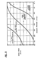
- Figure 3 shows the projected complete mapping of Mass Fraction of material having a magnetic energy product above 14.7 megagaussoersteds versus Wheel Speed and Pressure.
- Figure 3 clearly shows a region of parameter space where the mass fraction above about 14.7 to 15 megagaussoersteds, a bench mark for the onset of interaction in the "2-14-1" system, is maximized.
- the fractions of ferromagnetic alloy materials had a bimodel distribution of magnetic parameters, one fraction having a maximum magnetic energy product several kiloOersteds below 14.7 to 15 KOe, and the other fraction having a magnetic energy product above about 15 KOe.This region is seen to increase with reductions in pressure and increases in wheel speed.
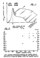
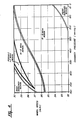
- Figure 4 shows the projected complete mapping of Maximum Magnetic Energy Product of the highest maximum magnetic energy product fraction recovered versus Wheel Speed and Pressure.
- the maximum energy product is a function of at least wheel speed and pressure.
- Figure 4 shows that there is a threshold pressure and that pressures must be maintained below this threshold pressure (which is a function of at least, e.g., orifice diameter, orifice to wheel spacing, and material properties) to obtain the desired narrow grain size distribution.
- the threshold pressure is 700 mm Hg absolute (i.e., minus 60 mm Hg gauge).
- the highest values of energy product are not obtained. These highest values are only obtained below 600 mm Hg to 700 mm Hg absolute for the orifice diameters, orifice to wheel distances, and orifice pressures utilized in Example I.
- the best results are obtained at chamber pressures below about 300 mm Hg to 400 mm Hg absolute, and preferably below about 200 mm Hg to 400 mm Hg.
- threshold pressures for other sets of parameters may be determined by routine experimentation utilizing the principles described herein.
- Wheel Speed at the pressures we have investigated should be in the range of 20 to 30 meters/second, and preferably about 20 to 25 meters/second, depending on the chamber pressure.
- the process allows a degree of process control where the components of quench associated with (1) forced convective cooling by the argon gas at the free surface of alloy, and (2) conduction to the chill surface may be individually controlled.
- FIGs 5, 6, and 7 Apparatus useful in subatmospheric pressure melt spinning of fine grain materials according to the method of the invention is shown in Figures 5, 6, and 7.
- Figures 5 and 6 show a melt spinner 1.
- the melt spinner includes a pressure vessel 11. Within the pressure vessel 11 is a melt spinning assembly 21. This assembly provides a substantially vibration free support for the melt spinning wheel 35 and a ball bearing shaft 37.
- the shaft 37 and the melt spinning wheel 35 are driven by motor 41, e.g., through pulleys 45.
- the crucible assembly 101 includes a crucible 111, for example, a mullite or quartz crucible 111 with an orifice 121 in proximity to the melt spinning wheel 35.
- a plug rod 131 is provided to controllably open the orifice 121 and allow the flow of molten alloy from the crucible 111.
- the plug rod 131 is controllably opened by a solenoid coil 135 with a power supply.
- the crucible 111 and alloy contents are heated, e.g., by an induction heating coil 141.
- induction heating provides vigorous mixing in the molten alloy. This mixing and turbulence has an adverse effect on the instantaneous quench parameters.
- induction heating is utilized with an electric field, i.e., in the coils 141, that is electrically decoupled from the molten metal, but thermally coupled thereto, as by a supceptor 151, indirect heating of the melt is obtained, e.g., indirect inductive heating, and in this way a quiescent melt is obtained in the crucible 111.
- a quiescent melt as obtained, for example by indirect inductive heating, with an electric field that is electrically decoupled from but thermally coupled to the molten alloy, as by supceptor 151
- a high wheel speed e.g., above about 20 to 25 meters per second
- a low environmental pressure e.g., below about 700 mm Hg absolute, and preferably between about 200 to 400 mm Hg absolute
- Low pressure melt spinning has resulted in the production of a "2-14-1"-type ferromagnetic alloy having a P42/mnm, tetragonal crystallography, and enhanced permanent (hard) magnetic parameters.
- a further advantage of the low pressure method that we have observed is the ability to produce an iron rich, ferromagnetic 2-14-1 type alloy that is both rich in iron, and substantially free of soft magnetic, cubic iron phases (i.e., alpha iron) at iron concentrations where magnetically significant cubic iron phases have been reported by others.
- the quench parameters obtained through the use of low pressures and high wheel speeds results in very high yields of enhanced parameter ferromagnetic alloy material, e.g., above about 40 weight percent and even above about 60 or more weight percent material exceeding prior art, i.e., the Stoner and Wohlfarth upper limits for non-interactive ferromagnetic materials, and above 10 to 20 weight percent of ferromagnetic 2-14-1 type materials having magnetic energy product above 17 megagaussoersteds.
- the subatmospheric pressure method of rapid solidification is followed by a sorting process to separate "overquenched” and “underquenched” factions, thereby providing a "cut” of enhanced parameter material.
- the sorted and separated "cut" of enhanced parameter material may have a very narrow morphological and parametric distribution, and be substantially free of either or both of (1) very fine crystallite size, low coercivity, low energy product, "overquenched” material and/or (2) very large crystallite size, low remanence, low energy product, "underquenched” material.
- Figure 8 shows an integrated, two step process.
- the herein described low pressure rapid solidification process is utilized to synthesize a flake-like or plate-like, brittle, magnetic alloy with a narrow crystallite size distribution about a mean crystallite size.
- the flakes are recovered and separated into enhanced parameter and low energy product factions by magnetic sorting.
- the low energy product fractions may be remelted, heat treated, or even used directly.
- a magnetic field is applied to the particulate solid or classified portion thereof.
- the magnetic field has a low enough field strength (H* in Figure 9) to avoid substantial magnetization of an enhanced energy product fraction but high enough to effect induced magnetization of low energy product fraction.
- the lower energy product fraction will be magnetized and attracted to the magnetic separator, while the higher energy product fraction will be left behind.
- This step may be stepwise repeated with higher applied magnetic fields until all of the particulate solid has been classified according to energy product.
- the underquenched, coarse grain material may be utilized as a low energy product commodity, or recycled, i.e., remelted.
- the fine grain, overquenched material may be utilized as a low energy product commodity, recycled (i.e. remelted), or heat treated to increase the grain size.
- This difference in induced magnetization allows mechanical separation of a first portion primarily composed of "enhanced parameter” particles, and magnetic separation of "overquenched" low complete magnetization magnetic property particles.
- Magnetic separation as used herein means the separation, i.e., sorting, of materials based on a difference in magnetic characteristics, referred to generally as “magnetic attractability.” "Magnetic attractability” is defined and described in Warren L. McCabe and Julian C. Smith, Unit Operations of Chemical Engineering , Mc-Graw Hill Book Company, Inc., New York, (1956), at pages 388-391, incorporated herein by reference.
- a method of magnetic separation, useful in practising the invention herein, is to place an electromagnet close to the particulate material. Materials of low induced magnetized are not attracted to the electromagnet, while materials of relatively higher induced magnetization are collected on the face of the electromagnet.
- the magnetic materials which may be fabricated by the method of the invention are ferromagnetic alloys of ferromagnetic transition metals, e.g., Fe, Co, and Ni, with other metals, as rare earth metals.
- the magnetic alloy material is an alloy of iron, optionally with other transition metals, as cobalt, a rare earth metal or metals, as neodymium, or praseodymium, optionally with lanthanum, boron, and, optionally, a modifier.
- the magnetic alloy material is an alloy of a ferromagnetic transition metal as iron or cobalt, with a lanthanide, as samarium, and, optionally, a modifier.
- Exemplary modifiers are silicon, aluminum, and mixtures thereof.
- the amount of modifier, when present, is at a level, in combination with the quench parameters, to give the above described isotropic magnetic parameters morphologies.
- the magnetic alloy may be of the type [Rare Earth Metal(s)]-[Transition Metal(s)]-[Modifier(s)], for example [Nd,Sm]-[Fe, Co]-[Si, Al].
- Another interacting alloy may be of the type [Rare Earth Metal (s)]-[Transition Metal (s)]-Boron-[modifier(s)], for example [Rare Earth Metal(s)]-[Fe,Co]-Boron-[modifier(s)], and [Rare Earth Metal(s)]-[Fe,Co,Mn]-Boron-[modifier(s)].
- the magnetic alloy material may be of the RE2TM14B type, also equivalently referred to in the art as the Nd2Fe14B -type, the 2-14-1 type, and/or the tetragonal P42/mnm type.
- concentrations of the transition metal greater than 85 atomic percent can be provided in the 2-14-1 type structure.
- the transition metals may be present within the 2-14-1 type phase at levels above the normal stochiometric and solubility limits of Fe and/or Co in the 2-14-1 type phase, i.e., the excess Fe and/or Co is not in an exsolved transition metal phase, as an exsolved cubic iron phase in the case of excess iron. This allows for a larger number of transition metal electrons (capable of ferromagnetic spin alignment) then would heretofore be expected from equilibrium solidification and thermodynamic considerations.
- the extremely rapid solidification of an Fe and/or Co rich, rare earth lean, tetragonal P42/mnm material allows the transition metal stoichiometric coefficient a to be above 85, e.g., up to 88.5 or more, and the rare earth metal stoichiometric coefficient b to be below l0, e.g. as low as 8.
- transition metal stoichiometric coefficient a to be above 85, e.g., up to 88.5 or more
- the rare earth metal stoichiometric coefficient b to be below l0, e.g. as low as 8.
- the rare earth metal is a lanthanide preferably chosen from neodymium and praseodymium, optionally with other lanthanides (one or more of La, Ce, Sm, Eu, Gd, Tb, Dy, Ho, Er, Tm, Yb and Lu), Sc, Y, and mixtures thereof present.
- rare earth metals are those that exhibit one or more of the following characteristics: (1) the number of f-shell electrons is neither 0 (as La with zero f orbital electrons), 7 (as Gd with 7 f orbital electrons) or 14 (as Lu with 14 f orbital electrons), (2) low molecular weight lanthanides, such as La, Ce, Pr, Nd, and Sm, (3) lanthanides that couple ferromagnetically with iron, as Nd and Pr, or (4) relatively inexpensive lanthanides, as La, Ce, Pr, and Nd. Especially preferred lanthanides are Nd and Pr.
- Various commercial and/or byproduct mischmetals may be used. Especially preferred mischmetals are those rich in Nd and/or Pr, optionally with small amounts of lanthanum.
- Raney nickel catalysts show a bimodal pore size distribution, sometimes termed a bidisperse structure, or macro-micro distribution. This is the case, for example, for most pelletized, extruded, deposited, agglomerated, or sintered Raney nickel catalysts.
- a "fine" pore structure within each of original particles of the Raney nickel and a “coarse” pore structure around the original particles of the Raney nickel are very fine pore structure within each of original particles of the Raney nickel and a "coarse” pore structure around the original particles of the Raney nickel.
- the diffusion mechanism between and around the particles is bulk diffusion, while the diffusion mechanism within the particles may be either bulk diffusion or Knudsen diffusion.
- the precursor alloy e.g., of a transition metal such as Ni and/or Fe, preferably Ni, and a leachable material, as Zr and/or Al, and preferably Al, optionally with other materials, is solidified under subatmospheric pressure conditions to produce a particulate, i.e., flake, product rich in the desired morphology and parameters.
- the low pressure helps control convective heat transfer from the metal to the gas, thereby providing more precise control of the uniformity of the heat transfer rate, and/or that the low gas pressure reduces the tendency towards formation of thermally insulating gas films between the solidifying metal and the chill surface, and/or that the low pressure allows dissolved gases to be exsolved.
- a supply of the molten transition metal-leachable material precursor is formed in a vessel in proximity to the chill surface, and a stream of the molten precursor is ejected from the vessel, through a subatmospheric pressure environment, typically comprising a non-reactive gas, onto a rapidly moving chill surface.
- the molten stream impinges onto the chill surface in the subatmospheric pressure environment causing the quenched material, e.g., a discontinuous stream of particles and flakes of the alloy, to be thrown off of the rapidly moving chill surface.
- These particles travel through the subatmospheric pressure environment and are recovered as a fine crystallite size alloy having a high fraction of material with a crystallographic size distribution closely distributed about a mean size.
- the particulate product of the subatmospheric pressure rapid solidification process containing uniformfine grain regions of transition metal and uniform fine grain regions of leachable material are then leached, e.g., in aqueous alkaline medium, as aqueous potassium hydroxide or aqueous sodium hydroxide, so as to remove the leachable material, leaving behind a porous catalytic solid network of substantially uniform diameter pores.
- the invention may be understood by reference to the following examples utilizing the method of the invention for the synthesis of enhanced parameter materials.
- the examples reported herein below are arranged in two examples.
- the first example illustrates the high yields, both mass percent of enhanced parameter material, and maximum magnetic energy product of a highest energy product fraction, as a function of chamber pressure and wheel speed, where magnetic separation, i.e., sorting has been used to effect separation of fraction.
- the second example demonstrates the broad compositional range (greater than the equilibrium stability range for 2-14-1 type materials) over which enhanced parameter magnetic materials can be synthesized by the method of the invention.
- the compositional range exceeds the predictions of the prior art, and is an advantageous result of the methods described herein.
- a macroscopically homogeneous ingot was first prepared by melting together the proper mixture of iron, neodymium, praseodymium, other rare earths, boron, silicon, and aluminum. Thereafter, portions of each ingot were melted and rapidly quenched using melt-spinning to form fragments of ribbon. The ribbon segments were then separated into high and low parameter fractions by a magnetic separation process. The separated segments were then pelletized for testing.
- individual samples are designated by a code comprising a three digit number, two letters, a number and, optionally, a number in parenthesis.
- the first three digits are the alloy number of the original ingot.
- the two letters identify the individual melt spin run numbers from that ingot.
- the numbers in parenthesis are the individual flake numbers, and are used only for flake samples, and not for pellet samples.
- the precursor alloys were generally prepared from the elemental components: iron (99.99% pure electrolytic iron flake), ferroboron boron (99.7% crystalline boron), Nd and Pr pure rods (99.9% rare earth metals), and silicon (99.99% Si crystals). In some cases, higher purity material was used. In other cases, commercial-grade rare-earth products were used, containing up to 15 weight percent iron and up to several weight percent of rare earths other than Nd and Pr. In addition to elemental boron, a ferroboron material containing 18 weight percent boron and the remainder iron was used as a source of boron.
- the components were weighed out in the appropriate proportions and melted together to form a homogeneous bulk ingot by vacuum induction melting.
- the samples were melted under a partial pressure of argon in either quartz or magnesia crucibles. They were taken to a temperature above 1400 Centigrade and held for thirty minutes with agitation to obtain a homogeneous ingot. After solidifying and cooling, the ingot was recovered from the crucible, an outer skin of reaction product was removed, and the ingot broken up into particles suitable for melt spinning. Composition checks were made on samples of the ingot material to check for homogeneity.
- Preparing the quenched material from the ingot was performed in a subatmospheric pressure pressure melt-spinning system.
- the system includes a vacuum vessel with a copper wheel twenty inches in diameter, four inches wide and three inches thick.
- the vacuum chamber was evacuated, and thereafter pressurized with an inert atmosphere to a pre-set subatmospheric pressure.
- the crucible was a mullite cylinder 44 mm inside diameter 52 mm outside diameter by about 26 cm long, with a 54 mm inside diameter, 66 mm outside diameter, 11 cm long graphite receptor surrounding the crucible, between the crucible and the induction coils.
- the crucible orifice was typically a circular hole in the crucible bottom, between 0.5 and 1.5 mm in diameter, and the crucible was positioned with the orifice 15 to 30 mm from the wheel surface.
- the low pressure method of rapid solidification of the invention was seen to provide both (1) better control of the mean crystallite size, and (2) a narrower distribution of crystallite sizes about this mean then did atmospheric pressure rapid solidification.
- a laboratory electromagnet was built for the magnetic separation.
- the laboratory electromagnet utilized a 3 centimeter long by 3 centimeter diameter iron bar wrapped with 200 turns of 26 AWG copper wire.
- the power supply to the electro-magnet was a 10 volt-1 ampere D.C. power supply.
- Particle fragments prepared as described above, were separated by sieving into a minus 60 mesh (250 micron) fraction, a minys 160 mesh plus 60 mesh (100 micron to 750 micron) fraction, and a plus 150 mesh (100 micron) fraction.
- the 150 to 250 micron fraction was then separated into enhanced magnetic parameter and low magnetic parameter fractions.
- the low magnetic parameter flakes were drawn to the electromagnet and the enhanced parameter flakes were left behind in the first pass. Approximately 90 percent of flakes left behind had an energy product greater than 15 MGOe.
- Magnetic separation can be carried out sequentially, with increasing magnetic field, H, on each pass.
- H increasing magnetic field
- the demarcation between the materials having relatively high magnetic parameters at substantially complete magnetization (and left behind by the weak magnetic field used for the separation) and the material having relatively lower magnetic parameters at substantially complete magnetization (and removed by the weak magnetic field used for the separation) was increased on each succeeding pass with increasing magnetic field, H.
- Figure 5 of commonly assigned copending U.S. Application Serial No. 063,936 of John E. Keem, et al hereby specifically incorporated herein by reference clearly shows this result.
- the green pellets were weighed on a Mettler H-80 automatic electrobalance calibrated to 0.1 milligram accuracy.
- the green pellets were then placed in vials of impregnating adhesive (e.g., Loctite 609). After a few minutes, the pellets were removed from the vials, and the excess adhesive was removed.
- the pellets were then cured in a vacuum oven at a pressure of less than 10 mm Hg and a temperature of 50 C to 90 C for 10 to 15 minutes.
- the bonded magnets produced in this way contain approximately 3 wt.% adhesive, and were 2.95 mm in diameter and from 3.12 to 3.30 mm long.
- Measurements of magnetic properties were made using a Model 9500 computer-controlled vibrating-sample magnetometer (VSM) manufactured by LDJ, Inc., having a maximum applied magnetic field of 22 kOe.
- the values of magnetic field H were determined under feedback-control with a calibrated Hall probe.
- the measurement software was modified in-house to permit measurement of both major and minor hysteresis loops of permanent magnet materials with high coercive forces.
- the calibration of the magnetization M was checked using a standard (soft magnetic) nickel sphere (from the U.S. National Bureau of Standards) of measured weight.
- the calculation of the magnetization of the magnetic materials required a measurement of the sample mass of order 0.12 to 0.15 gram for a typical pellet using a Cahn-21 automatic electrobalance (with precision to 1 microgram), and an estimate of the density.
- the measurement was carried out by ramping the field from zero to a maximum magnetic field, typically 22 kOe, through zero again to a negative maximum, and then back through zero to the positive maximum again, while the entire hysteresis loop was recorded, i.e., magnetization M vs. applied magnetic field H.
- the remanent magnetization or remanence Br the positive y-intercept of the hysteresis curve
- H ci the negative x-intercept of the hysteresis curve
- the applied field of 22 kOe was sufficient to "close" the hysteresis loops.
- H int H app - NM
- H int the field inside the material
- H app the externally applied field
- M the magnetization of the material measured at the applied field
- N the demagnetizing factor which simulates the influence of the field produced by the material on itself.
- the demagnetizing factors used ranged between 0.25 and 0.37 depending on the dimensions of the pellet and its orientation with respect to the applied field.
- a saturation magnetization range of 15.26 kilogauss (Sample 556AA02) to 16.2 kilogauss (Samples 561AA02 and 561AA03) was used for the calculation of (1) the remanence ratio, (Mr/M sat ), and (2) the ratio of Energy Product to (M sat/4 )2.
- the saturation magnetization was determined from measurements made at the Francis Bitter National Magnet Laboratory utilizing a procedure described in J.E. Keem, G.B. Clemente, A.M. Kadin, and R.W. McCallum, Magnetism Of HiRem Materials , presented October 12, 1987 at ASM Materials Week, which is hereby specifically incorporated herein by reference.
- the 539AA ingot from which the twenty melt spins described in the Example were made was produced by vacuum induction melting as described in Section B above.
- the bulk chemical analysis on the ingot gave the composition shown in Table I-1.
- the ribbons were spun on the above described 20 inch diameter melt spinner at Wheel Speeds ranging from 22 to 30 meters per second, and chamber pressures ranging from 10 to 760 mm Hg (absolute).
- Figure 3 is a plot of the mass fraction of material above about 15 megagaussoersteds versus Wheel Speed and Pressure. To be noted in that there is a range of Wheel Speed and absolute Pressure that produces a local maximum in the yield of material about 15 megagaussoersteds. This is mapped by the empirical relationship 30-[8/320]P c V s 30[80/160]P c
- Figure 4 is a plot of the magnetic energy product of the enhanced parameter fraction as a function of Wheel Speed and chamber pressure. This shows the narrowness of the highest energy product region, and the increasing energy product with Wheel Speed.
- Example II illustrate the applicability of the method to obtain the morphology necessary for enhanced magnetic parameters in lanthanum containing 2-14-1 type materials, in cobalt containing 2-14-1 type materials, in 2-14-1 type materials at low concentrations of Si and/or Al modifiers, and in 2-14-1 type materials that are hyperstoichiometric in Fe and/or hypostoichiometric in rare earth.
- the ability of the low pressure melt spinning method to produce 2-14-1 type materials that are hyperstoichiometric in Fe, and/or hypostoichiometric in rare earth, and have enhanced parameters is especially surprising in light of the clear teaching in Matsuura, et al "Phase Diagram of the Nd-Fe-B Ternary System," Japn. J.
- the ingots of iron, praseodymium, neodymium, lanthanum, boron and silicon were prepared following the procedure described in Section B. PREPARATION OF BULK ING0T, above.
- the ingots had an average elemental analysis, in atomic percent by ICP and wet chemistry shown in Table II-1 below.
- the melt spinner product was in the form of flakes which appeared to be comprised of randomly oriented, equiaxed crystallites.
- the flakes were magnetically separated as described in Section D MAGNETIC SEPARATION OF THE QUENCHED PARTICLES, above.
- Magnetic properties were measured as described in Section H.2, MAGNETIC MEASUREMENTS, Pelletized Product, above.
- the value of the saturation magnetization used for the calculation of the remanence ratio, (Mr/M sat ), and (2) the ratio of Energy Product to (M sat/4 )2. was determined from measurements made at the Francis Bitter National Magnet Laboratory utilizing a procedure described in J.E. Keem, G.B. Clemente, A.M. Kadin, and R.W. McCallum, Magnetism Of HiRem Materials , presented October 12, 1987 at ASM Materials Week, which is hereby specifically incorporated herein by reference.
- Sample 561 had a hyperstoichiometric iron content, i.e., the sample had an iron content above the level at which the prior art teaches that a second, iron rich phase precipitates, i.e., above about 85 atomic percent, a rare earth content below about 10 atomic percent, and did not contain detectable amounts of either Si or Al.
- the materials of Sample 561AA exhibited enhanced, that is, interactive properties, that is, isotropic energy products above (M sat /4)2 and isotropic remanences above (M sat /2), as shown in Table II-3 below.
- Sample 556AA cobalt was partially substituted for iron.
- the materials of Sample 556AA exhibited interactive properties, i.e., isotropic energy product above (M sat /4)2, and isotropic remanences above (M sat /2), as shown in Table II-3 below.
Landscapes
- Engineering & Computer Science (AREA)
- Chemical & Material Sciences (AREA)
- Power Engineering (AREA)
- Materials Engineering (AREA)
- Mechanical Engineering (AREA)
- Metallurgy (AREA)
- Organic Chemistry (AREA)
- Crystallography & Structural Chemistry (AREA)
- Inorganic Chemistry (AREA)
- Manufacturing & Machinery (AREA)
- Manufacture Of Metal Powder And Suspensions Thereof (AREA)
- Hard Magnetic Materials (AREA)
Applications Claiming Priority (2)
| Application Number | Priority Date | Filing Date | Title |
|---|---|---|---|
| US07/191,626 US4867785A (en) | 1988-05-09 | 1988-05-09 | Method of forming alloy particulates having controlled submicron crystallite size distributions |
| US191626 | 1988-05-09 |
Publications (2)
| Publication Number | Publication Date |
|---|---|
| EP0341435A2 true EP0341435A2 (de) | 1989-11-15 |
| EP0341435A3 EP0341435A3 (de) | 1990-05-09 |
Family
ID=22706228
Family Applications (1)
| Application Number | Title | Priority Date | Filing Date |
|---|---|---|---|
| EP89106374A Withdrawn EP0341435A3 (de) | 1988-05-09 | 1989-04-11 | Verfahren zur Herstellung von ferromagnetischen Legierungsfestkörperteilchen durch rasches Abschrecken |
Country Status (3)
| Country | Link |
|---|---|
| US (1) | US4867785A (de) |
| EP (1) | EP0341435A3 (de) |
| JP (1) | JPH0219407A (de) |
Cited By (3)
| Publication number | Priority date | Publication date | Assignee | Title |
|---|---|---|---|---|
| EP0529148A3 (en) * | 1991-08-29 | 1993-10-13 | Tdk Corporation | Permanent magnet material and method for making |
| DE10019813A1 (de) * | 2000-04-20 | 2001-12-13 | Infineon Technologies Ag | Avalanchefestes Halbleiterbauelement |
| CN109256250A (zh) * | 2017-07-13 | 2019-01-22 | 北京中科三环高技术股份有限公司 | 一种含Ce稀土永磁体及其制备方法 |
Families Citing this family (23)
| Publication number | Priority date | Publication date | Assignee | Title |
|---|---|---|---|---|
| GB9203689D0 (en) * | 1992-02-20 | 1992-04-08 | Euro Celtique Sa | Pharmaceutical composition |
| US5403408A (en) * | 1992-10-19 | 1995-04-04 | Inland Steel Company | Non-uniaxial permanent magnet material |
| DE4417105C2 (de) * | 1994-05-16 | 1997-03-06 | Forschungszentrum Juelich Gmbh | Verfahren zur Gewinnung rißfreier Kristalle |
| US6332933B1 (en) | 1997-10-22 | 2001-12-25 | Santoku Corporation | Iron-rare earth-boron-refractory metal magnetic nanocomposites |
| CN1265401C (zh) | 1998-07-13 | 2006-07-19 | 株式会社三德 | 制造纳米复合磁性材料的方法以及制造粘结磁体的方法 |
| US6524399B1 (en) | 1999-03-05 | 2003-02-25 | Pioneer Metals And Technology, Inc. | Magnetic material |
| US7195661B2 (en) * | 1999-03-05 | 2007-03-27 | Pioneer Metals And Technology, Inc. | Magnetic material |
| US6389100B1 (en) | 1999-04-09 | 2002-05-14 | Osmic, Inc. | X-ray lens system |
| US6421417B1 (en) | 1999-08-02 | 2002-07-16 | Osmic, Inc. | Multilayer optics with adjustable working wavelength |
| US6870896B2 (en) | 2000-12-28 | 2005-03-22 | Osmic, Inc. | Dark-field phase contrast imaging |
| US6804324B2 (en) * | 2001-03-01 | 2004-10-12 | Osmo, Inc. | X-ray phase contrast imaging using a fabry-perot interferometer concept |
| US6510200B1 (en) | 2001-06-29 | 2003-01-21 | Osmic, Inc. | Multi-layer structure with variable bandpass for monochromatization and spectroscopy |
| US6643353B2 (en) | 2002-01-10 | 2003-11-04 | Osmic, Inc. | Protective layer for multilayers exposed to x-rays |
| US20040016769A1 (en) * | 2002-03-15 | 2004-01-29 | Redmond Scott D. | Hydrogen storage, distribution, and recovery system |
| US7169489B2 (en) * | 2002-03-15 | 2007-01-30 | Fuelsell Technologies, Inc. | Hydrogen storage, distribution, and recovery system |
| US20030234010A1 (en) * | 2002-06-25 | 2003-12-25 | Redmond Scott D. | Methods and apparatus for converting internal combustion engine (ICE) vehicles to hydrogen fuel |
| US7399325B1 (en) | 2002-03-15 | 2008-07-15 | Fuelsell Technologies, Inc. | Method and apparatus for a hydrogen fuel cassette distribution and recovery system |
| US7011768B2 (en) * | 2002-07-10 | 2006-03-14 | Fuelsell Technologies, Inc. | Methods for hydrogen storage using doped alanate compositions |
| US20040065171A1 (en) * | 2002-10-02 | 2004-04-08 | Hearley Andrew K. | Soild-state hydrogen storage systems |
| JP4938510B2 (ja) * | 2007-03-09 | 2012-05-23 | 帝国チャック株式会社 | 引込式チャック装置 |
| US8821650B2 (en) * | 2009-08-04 | 2014-09-02 | The Boeing Company | Mechanical improvement of rare earth permanent magnets |
| CN104128256A (zh) * | 2014-07-28 | 2014-11-05 | 鞍钢集团矿业公司 | 永磁筒式磁选机用均匀布矿器 |
| CN115605622B (zh) * | 2021-04-28 | 2025-10-31 | Neo新材料技术(新加坡)私人有限公司 | 生产磁性材料的方法和系统 |
Family Cites Families (8)
| Publication number | Priority date | Publication date | Assignee | Title |
|---|---|---|---|---|
| FR84749E (fr) * | 1961-10-05 | 1965-04-02 | Centre Nat Rech Metall | Procédé de traitement et de concentration de minerais |
| US4264641A (en) * | 1977-03-17 | 1981-04-28 | Phrasor Technology Inc. | Electrohydrodynamic spraying to produce ultrafine particles |
| GB1604019A (en) * | 1978-05-31 | 1981-12-02 | Wiggin & Co Ltd Henry | Atomisation into a chamber held at reduced pressure |
| US4306901A (en) * | 1980-05-27 | 1981-12-22 | Massachusetts Institute Of Technology | Process for forming steel product from iron while avoiding the liquid state |
| US4647305A (en) * | 1983-07-19 | 1987-03-03 | Nippon Kinzoku Co., Ltd. | Process for manufacturing amorphous alloy powders |
| EP0260746A1 (de) * | 1986-09-17 | 1988-03-23 | Koninklijke Philips Electronics N.V. | Verfahren zur Herstellung von Spänen aus magnetischem Material mit Vorzugsrichtung der Kristallite, Späne und Magnete, die daraus hergestellt sind |
| US4723994A (en) * | 1986-10-17 | 1988-02-09 | Ovonic Synthetic Materials Company, Inc. | Method of preparing a magnetic material |
| US4781754A (en) * | 1987-09-24 | 1988-11-01 | General Motors Corporation | Rapid solidification of plasma sprayed magnetic alloys |
-
1988
- 1988-05-09 US US07/191,626 patent/US4867785A/en not_active Expired - Lifetime
-
1989
- 1989-04-11 EP EP89106374A patent/EP0341435A3/de not_active Withdrawn
- 1989-05-09 JP JP1115955A patent/JPH0219407A/ja active Pending
Cited By (4)
| Publication number | Priority date | Publication date | Assignee | Title |
|---|---|---|---|---|
| EP0529148A3 (en) * | 1991-08-29 | 1993-10-13 | Tdk Corporation | Permanent magnet material and method for making |
| DE10019813A1 (de) * | 2000-04-20 | 2001-12-13 | Infineon Technologies Ag | Avalanchefestes Halbleiterbauelement |
| DE10019813C2 (de) * | 2000-04-20 | 2002-10-31 | Infineon Technologies Ag | Avalanchefestes Halbleiterbauelement |
| CN109256250A (zh) * | 2017-07-13 | 2019-01-22 | 北京中科三环高技术股份有限公司 | 一种含Ce稀土永磁体及其制备方法 |
Also Published As
| Publication number | Publication date |
|---|---|
| EP0341435A3 (de) | 1990-05-09 |
| US4867785A (en) | 1989-09-19 |
| JPH0219407A (ja) | 1990-01-23 |
Similar Documents
| Publication | Publication Date | Title |
|---|---|---|
| US4867785A (en) | Method of forming alloy particulates having controlled submicron crystallite size distributions | |
| EP0108474B1 (de) | RE-TM-B Legierungen, deren Herstellung und permanent Magnete die solche Legierungen enthalten | |
| EP0411571B1 (de) | Seltenerdpulver für Dauermagnet, Herstellungsverfahren und Verbundmagnet | |
| US6120620A (en) | Praseodymium-rich iron-boron-rare earth composition, permanent magnet produced therefrom, and method of making | |
| JPH0352528B2 (de) | ||
| US5164104A (en) | Magnetic material containing rare earth element, iron, nitrogen, hydrogen and oxygen and bonded magnet containing the same | |
| CA1271394A (en) | Enhanced remanence permanent magnetic alloy and bodies thereof and method of preparing same | |
| US5976271A (en) | Method for the preparation of rare earth based anisotropic permanent magnet | |
| US5474623A (en) | Magnetically anisotropic spherical powder and method of making same | |
| US4834811A (en) | Method of manufacturing, concentrating, and separating enhanced magnetic parameter material from other magnetic co-products | |
| US5116434A (en) | Method of manufacturing, concentrating, and separating enhanced magnetic parameter material from other magnetic co-products | |
| US4099995A (en) | Copper-hardened permanent-magnet alloy | |
| US4900374A (en) | Demagnetization of iron-neodymium-boron type permanent magnets without loss of coercivity | |
| EP0652572B1 (de) | Heissgepresste Magneten | |
| US4973415A (en) | Rapidly quenched ribbon magnet and plastic magnet containing powders of the rapidly quenched ribbon magnet | |
| WO2000048209A9 (en) | Praseodymium-rich iron-boron-rare earth composition, permanent magnet produced therefrom, and method of making | |
| JPH0620813A (ja) | 希土類異方性永久磁石粉末及びその製造法 | |
| EP0229946B1 (de) | Permanentmagnetische Legierung | |
| JP3488354B2 (ja) | 微細結晶永久磁石合金及び等方性永久磁石粉末の製造方法 | |
| CN113571279A (zh) | 磁体及其制造方法 | |
| CN113571278A (zh) | 磁粉、磁粉的形成方法、稀土类烧结永磁体及其制备方法 | |
| JPH07109504A (ja) | 異方性ボンド磁石用原料粉末の製造方法 | |
| JPS63216307A (ja) | 磁石用合金粉末 | |
| JPH0688159A (ja) | 希土類磁石並びに希土類磁石合金粉末とその製造方法 | |
| EP0599815B1 (de) | Magnetische Legierung und Herstellungsverfahren |
Legal Events
| Date | Code | Title | Description |
|---|---|---|---|
| PUAI | Public reference made under article 153(3) epc to a published international application that has entered the european phase |
Free format text: ORIGINAL CODE: 0009012 |
|
| AK | Designated contracting states |
Kind code of ref document: A2 Designated state(s): DE FR GB IT NL |
|
| PUAL | Search report despatched |
Free format text: ORIGINAL CODE: 0009013 |
|
| AK | Designated contracting states |
Kind code of ref document: A3 Designated state(s): DE FR GB IT NL |
|
| 17P | Request for examination filed |
Effective date: 19900821 |
|
| 17Q | First examination report despatched |
Effective date: 19921026 |
|
| STAA | Information on the status of an ep patent application or granted ep patent |
Free format text: STATUS: THE APPLICATION IS DEEMED TO BE WITHDRAWN |
|
| 18D | Application deemed to be withdrawn |
Effective date: 19940208 |