EP0341401A2 - Radar transponder - Google Patents
Radar transponder Download PDFInfo
- Publication number
- EP0341401A2 EP0341401A2 EP89104913A EP89104913A EP0341401A2 EP 0341401 A2 EP0341401 A2 EP 0341401A2 EP 89104913 A EP89104913 A EP 89104913A EP 89104913 A EP89104913 A EP 89104913A EP 0341401 A2 EP0341401 A2 EP 0341401A2
- Authority
- EP
- European Patent Office
- Prior art keywords
- slits
- radar transponder
- transmission gate
- amplifying
- radar
- Prior art date
- Legal status (The legal status is an assumption and is not a legal conclusion. Google has not performed a legal analysis and makes no representation as to the accuracy of the status listed.)
- Granted
Links
Images

Classifications
-
- G—PHYSICS
- G01—MEASURING; TESTING
- G01S—RADIO DIRECTION-FINDING; RADIO NAVIGATION; DETERMINING DISTANCE OR VELOCITY BY USE OF RADIO WAVES; LOCATING OR PRESENCE-DETECTING BY USE OF THE REFLECTION OR RERADIATION OF RADIO WAVES; ANALOGOUS ARRANGEMENTS USING OTHER WAVES
- G01S13/00—Systems using the reflection or reradiation of radio waves, e.g. radar systems; Analogous systems using reflection or reradiation of waves whose nature or wavelength is irrelevant or unspecified
- G01S13/74—Systems using reradiation of radio waves, e.g. secondary radar systems; Analogous systems
- G01S13/76—Systems using reradiation of radio waves, e.g. secondary radar systems; Analogous systems wherein pulse-type signals are transmitted
- G01S13/767—Responders; Transponders
Definitions
- the present invention relates to a radar transponder which, on reception of a high frequency signal such as a microwave signal from a radar, responds to (synchronize with) the signal and transmits a high frequency response signal.
- a high frequency signal such as a microwave signal from a radar
- Fig. 1 is a circuit block diagram of a conventional radar transponder.
- reference numeral 1 is a receiving antenna, 2 a diode direct detector, 3 a video amplifier, 4 a control circuit, 5 a transmission gate circuit, 6 a sweep signal generator, 7 a microwave oscillator, 8 a transmitting antenna, and 16 a FET amplifier.
- the diode direct detector 2 and the FET amplifier 16 are integrated by a microwave integrated circuit (MIC).
- MIC microwave integrated circuit
- a microwave signal received by the receiving antenna 1 coming from a radar is amplified by the FET amplifier 1b, the amplified electric wave detected by the diode direct detector 2, the detected output is amplified by the video amplifier 3, and is sent to the control circuit 4.
- the control circuit 4 forms pulses for creating the transmission time of a radar transponder using an input video amplified signal and transfers the pulses to the transmission gate circuit 5.
- the transmission gate circuit 5 forms transmission gate pulses using the transferred output pulses from the control circuit, and the transmission gate pulses are input to the sweep signal generator 6 and the microwave oscillator 7.
- the sweep signal generator 6 generates saw-tooth voltage which wave form consists of a required number of saw-tooth pulses using the transmission gate pulses and transfers them to the microwave oscillator 7.
- the microwave oscillator 7 performs transmission for a fixed time set by the transmission gate pulses and performs frequency sweep in a regular frequency range using the saw-tooth output voltage.
- a frequency swept signal from the microwave oscillator 7 is propagated into the space by the transmitting antenna 8.
- the conventional radar transponder is composed as above-described, unnecessary waveguide electromagnetic field modes are generated in a waveguide composed of antenna housing and MIC portion, and the unnecessary waveguide electromagnetic field modes interfere with the FET amplifier 4. Thereby inherent performance of the FET amplifier 4 is not obtained. As a result, there is such a problem that the sufficient receiving sensibility is not obtained. There are also other problems, for example, one of them is that the performance of the MIC portion adjusted under the condition which the MIC portion is not connected to the antenna housing cannot be appear.
- the present invention is devised to solve the above-mentioned problems and it is an object of the present invention to suppress unnecessary waveguide electromagnetic field modes within the required frequency band generated in a waveguide formed in the inside of a radar transponder and secure a sufficient receiving sensitivity.
- the radar transponder mounts amplifying means and detecting means on an antenna housing via an elastic metal body.
- the elastic metal body is closely contacted with the antenna housing to form a waveguide having a volume smaller than that of the conventional one, and acts so as to make the required frequency band not higher than its cut-off frequency.
- unnecessary waveguide electromagnetic field modes within the required band does not occur. Accordingly, unnecessary interferences applied to the amplifying means such as a FET amplifier and the like are removed, thereby allowing the primary performance of the FET amplifier concerned to be obtained and a good receiving sensitivity of the radar transponder to be obtained.
- the performance obtained by adjusting the amplifying means and the detecting means in a state under which the both means are mounted on a fixed mounting plate can be easily reproduced after the both means are mounted on the antenna housing.
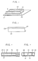
- Fig. 2 is a partial perspective view of a radar transponder in which a springy metal wall with slits is mounted on a MIC mounting plate.
- reference numeral 22 is a springy metal wall with slits as an elastic metal body which is provided at both sides on the diode direct detector 2 in the longitudinal direction and mounted on the upper part of the MIC mounting plate 21.
- Fig. 3 is a detailed drawing of the springy metal wall 22 with slits, and reference numeral 23 are a plenty of slits provided at the folded portion 221 of the upper side of the springy metal wall 22 with slits in order to give resilience to the metal wall.
- Fig. 4 is a sectional view showing a state in which the MIC mounting plate 21 having the springy metal wall 22 with slits thereon is mounted is further mounted on the antenna housing 20, and Fig. 5 is a side sectional view of Fig. 4.
- the radar electric wave received by a receiving antenna is converted from the electric wave propagation mode in a waveguide composed of the antenna housing 20 and the MIC mounting plate 21, that is, the TE mode to the electric wave propagation mode in the MIC portion, that is, the TEM mode by a ridge conversion unit 24.
- the mode-converted electric wave concerned is amplified by the FET amplifier connected to the ridge conversion unit 24 by soldering and the like, it is converted into a DC detected output by the diode direct detector 2.
- the DC detected output concerned is further amplified by the video amplifier (not shown), and the amplified output triggers the control circuit (not shown), thereby opening the transmission gate of the transmission gate circuit (not shown) and transmitting a response electric wave.
- the springy metal wall 22 with slits is provided on the both sides of the FET amplifier 16 and the diode direct detector 2 in the longitudinal direction and mounted on the MIC mounting plate 21 as shown in Fig. 2, if the metal wall 22 is assembled with the antenna housing 20 to form an unitary body as shown in Fig. 4 and Fig. 5, the springy metal wall 22 with slits is closely contacted with the antenna housing 20 by the aid of resilience based on the slits 23 to make perfect high frequency contact to the antenna housing 20 and to form a waveguide having a volume smaller than that of a conventional one.
- Such a radar transponder that the performances of the FET amplifier 16 and the diode direct detector 2 obtained by the adjustment after they are mounted on the MIC mounting plate 21 can be also easily reproduced after mounting them to the antenna housing 20 can be obtained.
- the springy metal wall 22 with slits may be mounted on the antenna housing 20 with the metal wall 22 held upside down.
- the slits 23 are formed on the end of the metal wall 22.
- the gist is that the whole of the metal wall 22 has resilience.
- the metal wall 22 concerned may form slits 23 with various shapes at the central portion thereof.
- a metal body implemented so as to obtain resilience using other means such as, for example, the means that the whole of the metal wall 22 is formed so as to be spring-shaped may be used without restriction to the embodiment in which slits are disposed at one portion of the metal wall concerned 22.
- the FET amplifier 16 is used as an amplifying means, other amplifiers such as a travelling-wave tube amplifier may be employed.
- the diode direct detector 2 is used as a detecting means, other kinds of detectors may be employed.
- the radar transponder since in a radar transponder having a receiving unit equipped with an amplifying means and a detecting means, the radar transponder is configurated so as to mount its amplifying means and detecting means via a metal body having resilience on the antenna housing, unnecessary waveguide electromagnetic field modes within the band are removed. This leads to the result that inherent performance as an amplifying means, for example, that of the FET amplifier can be obtained and a radar transponder having a good receiving sensitivity can be obtained.
Landscapes
- Engineering & Computer Science (AREA)
- Radar, Positioning & Navigation (AREA)
- Remote Sensing (AREA)
- Computer Networks & Wireless Communication (AREA)
- Physics & Mathematics (AREA)
- General Physics & Mathematics (AREA)
- Radar Systems Or Details Thereof (AREA)
- Waveguide Switches, Polarizers, And Phase Shifters (AREA)
- Waveguides (AREA)
Abstract
Description
- The present invention relates to a radar transponder which, on reception of a high frequency signal such as a microwave signal from a radar, responds to (synchronize with) the signal and transmits a high frequency response signal.
- Fig. 1 is a circuit block diagram of a conventional radar transponder. In Fig. 1, reference numeral 1 is a receiving antenna, 2 a diode direct detector, 3 a video amplifier, 4 a control circuit, 5 a transmission gate circuit, 6 a sweep signal generator, 7 a microwave oscillator, 8 a transmitting antenna, and 16 a FET amplifier. In this case, the diode
direct detector 2 and theFET amplifier 16 are integrated by a microwave integrated circuit (MIC). - Next, the operation will be described. A microwave signal received by the receiving antenna 1 coming from a radar is amplified by the FET amplifier 1b, the amplified electric wave detected by the diode
direct detector 2, the detected output is amplified by thevideo amplifier 3, and is sent to the control circuit 4. The control circuit 4 forms pulses for creating the transmission time of a radar transponder using an input video amplified signal and transfers the pulses to thetransmission gate circuit 5. Thetransmission gate circuit 5 forms transmission gate pulses using the transferred output pulses from the control circuit, and the transmission gate pulses are input to thesweep signal generator 6 and themicrowave oscillator 7. Thesweep signal generator 6 generates saw-tooth voltage which wave form consists of a required number of saw-tooth pulses using the transmission gate pulses and transfers them to themicrowave oscillator 7. Themicrowave oscillator 7 performs transmission for a fixed time set by the transmission gate pulses and performs frequency sweep in a regular frequency range using the saw-tooth output voltage. A frequency swept signal from themicrowave oscillator 7 is propagated into the space by the transmittingantenna 8. - Since the conventional radar transponder is composed as above-described, unnecessary waveguide electromagnetic field modes are generated in a waveguide composed of antenna housing and MIC portion, and the unnecessary waveguide electromagnetic field modes interfere with the FET amplifier 4. Thereby inherent performance of the FET amplifier 4 is not obtained. As a result, there is such a problem that the sufficient receiving sensibility is not obtained. There are also other problems, for example, one of them is that the performance of the MIC portion adjusted under the condition which the MIC portion is not connected to the antenna housing cannot be appear.
- The present invention is devised to solve the above-mentioned problems and it is an object of the present invention to suppress unnecessary waveguide electromagnetic field modes within the required frequency band generated in a waveguide formed in the inside of a radar transponder and secure a sufficient receiving sensitivity.
- The radar transponder according to the present invention mounts amplifying means and detecting means on an antenna housing via an elastic metal body.
- The elastic metal body is closely contacted with the antenna housing to form a waveguide having a volume smaller than that of the conventional one, and acts so as to make the required frequency band not higher than its cut-off frequency. By this, unnecessary waveguide electromagnetic field modes within the required band does not occur. Accordingly, unnecessary interferences applied to the amplifying means such as a FET amplifier and the like are removed, thereby allowing the primary performance of the FET amplifier concerned to be obtained and a good receiving sensitivity of the radar transponder to be obtained.
- Also, the performance obtained by adjusting the amplifying means and the detecting means in a state under which the both means are mounted on a fixed mounting plate can be easily reproduced after the both means are mounted on the antenna housing.
-
- Fig. 1 is a circuit block diagram showing a circuit configuration of a conventional radar transponder;
- Fig. 2 is a partial perspective view showing a part of a springy metal wall with slits mounted on a MIC mounting plate of a transponder of an embodiment according to the present invention;
- Fig. 3 is a detailed diagram showing the springy metal wall with slits shown in Fig. 2 in detail; and
- Fig. 4 and Fig. 5 are partial sectional views showing a receiving unit of the transponder of the embodiment according to the present invention.
- Fig. 2 is a partial perspective view of a radar transponder in which a springy metal wall with slits is mounted on a MIC mounting plate. In Fig. 2,
reference numeral 22 is a springy metal wall with slits as an elastic metal body which is provided at both sides on the diodedirect detector 2 in the longitudinal direction and mounted on the upper part of theMIC mounting plate 21. Fig. 3 is a detailed drawing of thespringy metal wall 22 with slits, andreference numeral 23 are a plenty of slits provided at the foldedportion 221 of the upper side of thespringy metal wall 22 with slits in order to give resilience to the metal wall. - Fig. 4 is a sectional view showing a state in which the
MIC mounting plate 21 having thespringy metal wall 22 with slits thereon is mounted is further mounted on theantenna housing 20, and Fig. 5 is a side sectional view of Fig. 4. - Next, the operation of Fig. 5 will be described. The radar electric wave received by a receiving antenna (not shown) is converted from the electric wave propagation mode in a waveguide composed of the
antenna housing 20 and theMIC mounting plate 21, that is, the TE mode to the electric wave propagation mode in the MIC portion, that is, the TEM mode by aridge conversion unit 24. After the mode-converted electric wave concerned is amplified by the FET amplifier connected to theridge conversion unit 24 by soldering and the like, it is converted into a DC detected output by the diodedirect detector 2. The DC detected output concerned is further amplified by the video amplifier (not shown), and the amplified output triggers the control circuit (not shown), thereby opening the transmission gate of the transmission gate circuit (not shown) and transmitting a response electric wave. - In this case, since the
springy metal wall 22 with slits is provided on the both sides of theFET amplifier 16 and the diodedirect detector 2 in the longitudinal direction and mounted on theMIC mounting plate 21 as shown in Fig. 2, if themetal wall 22 is assembled with theantenna housing 20 to form an unitary body as shown in Fig. 4 and Fig. 5, thespringy metal wall 22 with slits is closely contacted with theantenna housing 20 by the aid of resilience based on theslits 23 to make perfect high frequency contact to theantenna housing 20 and to form a waveguide having a volume smaller than that of a conventional one. In this way, since the construction of the waveguide formed by thespringy metal wall 22 with slits functions so that the required frequency band becomes not higher than the cut-off frequency, it does not generate unnecessary waveguide electromagnetic field mode at all. Accordingly, unnecessary interferences applied to theFET amplifier 16 are removed, thereby allowing the performance inherent to theFET amplifier 16 to be obtained. - Such a radar transponder that the performances of the
FET amplifier 16 and the diodedirect detector 2 obtained by the adjustment after they are mounted on theMIC mounting plate 21 can be also easily reproduced after mounting them to theantenna housing 20 can be obtained. - Incidentally, in the above-mentioned embodiment, though an example in which the
springy metal wall 22 with slits is mounted on theMIC mounting plate 21 with themetal wall 22 held in a state as shown in Fig. 2 is shown, thespringy metal wall 22 with slits may be mounted on theantenna housing 20 with themetal wall 22 held upside down. - In the above-mentioned embodiment, the
slits 23 are formed on the end of themetal wall 22. But, the gist is that the whole of themetal wall 22 has resilience. Accordingly, themetal wall 22 concerned may form slits 23 with various shapes at the central portion thereof. Further, if themetal wall 22 has resilience as a whole, a metal body implemented so as to obtain resilience using other means such as, for example, the means that the whole of themetal wall 22 is formed so as to be spring-shaped may be used without restriction to the embodiment in which slits are disposed at one portion of the metal wall concerned 22. - In the above-mentioned embodiment, though the
FET amplifier 16 is used as an amplifying means, other amplifiers such as a travelling-wave tube amplifier may be employed. Furthermore, though the diodedirect detector 2 is used as a detecting means, other kinds of detectors may be employed. - As described above, according to the present embodiment, since in a radar transponder having a receiving unit equipped with an amplifying means and a detecting means, the radar transponder is configurated so as to mount its amplifying means and detecting means via a metal body having resilience on the antenna housing, unnecessary waveguide electromagnetic field modes within the band are removed. This leads to the result that inherent performance as an amplifying means, for example, that of the FET amplifier can be obtained and a radar transponder having a good receiving sensitivity can be obtained. Also, this leads to the result that there can be obtained such a radar transponder as the inherent performances as an amplifying means and as a detecting means, for example, those of the FET amplifier and of the diode
direct detector 2 obtained by adjusting the both means on the fixed mounting plate can be easily reproduced after mounting those means on the antenna housing.
Claims (4)
Applications Claiming Priority (2)
| Application Number | Priority Date | Filing Date | Title |
|---|---|---|---|
| JP113475/88 | 1988-05-12 | ||
| JP63113475A JPH07111459B2 (en) | 1988-05-12 | 1988-05-12 | Radar transponder |
Publications (3)
| Publication Number | Publication Date |
|---|---|
| EP0341401A2 true EP0341401A2 (en) | 1989-11-15 |
| EP0341401A3 EP0341401A3 (en) | 1991-04-03 |
| EP0341401B1 EP0341401B1 (en) | 1994-07-13 |
Family
ID=14613208
Family Applications (1)
| Application Number | Title | Priority Date | Filing Date |
|---|---|---|---|
| EP89104913A Expired - Lifetime EP0341401B1 (en) | 1988-05-12 | 1989-03-18 | Radar transponder |
Country Status (4)
| Country | Link |
|---|---|
| US (2) | US4980689A (en) |
| EP (1) | EP0341401B1 (en) |
| JP (1) | JPH07111459B2 (en) |
| DE (1) | DE68916692T2 (en) |
Families Citing this family (15)
| Publication number | Priority date | Publication date | Assignee | Title |
|---|---|---|---|---|
| JPH07111459B2 (en) * | 1988-05-12 | 1995-11-29 | 三菱電機株式会社 | Radar transponder |
| WO1991010290A1 (en) * | 1989-12-28 | 1991-07-11 | Kabushiki Kaisha Toyota Chuo Kenkyusho | Mobile communication system and mobile communication equipment |
| US5172121A (en) * | 1991-04-30 | 1992-12-15 | Consolidated Rail Corp. | System for automatic identification of rail cars |
| USRE42773E1 (en) | 1992-06-17 | 2011-10-04 | Round Rock Research, Llc | Method of manufacturing an enclosed transceiver |
| US7158031B2 (en) | 1992-08-12 | 2007-01-02 | Micron Technology, Inc. | Thin, flexible, RFID label and system for use |
| JPH06281734A (en) * | 1993-03-25 | 1994-10-07 | Mitsubishi Electric Corp | Radar transponder |
| JPH0755918A (en) * | 1993-06-30 | 1995-03-03 | Mitsubishi Electric Corp | Search and rescue radar transponder |
| EP0647681B1 (en) | 1993-10-12 | 1999-08-11 | Elf Atochem S.A. | Article based on polyamide-polyolefin blend and comprising a weld line |
| GB9324534D0 (en) * | 1993-11-30 | 1994-01-19 | Marconi Gec Ltd | Circuit arrangement |
| US6239737B1 (en) * | 1994-07-15 | 2001-05-29 | Micron Technology, Inc. | Method and apparatus for attaching a radio frequency transponder to an object |
| US5724045A (en) * | 1994-09-22 | 1998-03-03 | Mitsubishi Denki Kabushiki Kaisha | Radar transponder |
| JP3106088B2 (en) * | 1995-05-26 | 2000-11-06 | 三菱電機株式会社 | Radar transponder |
| US6339385B1 (en) | 1997-08-20 | 2002-01-15 | Micron Technology, Inc. | Electronic communication devices, methods of forming electrical communication devices, and communication methods |
| US20090237290A1 (en) * | 2007-12-19 | 2009-09-24 | Michael Kishinevsky | Radar transponder |
| IT201600102764A1 (en) * | 2016-10-13 | 2018-04-13 | Univ Degli Studi Di Firenze | BISTATIC INTERFEROMETRIC TERRESTRIAL RADAR WITH TRANSPONDER |
Family Cites Families (17)
| Publication number | Priority date | Publication date | Assignee | Title |
|---|---|---|---|---|
| US2825042A (en) * | 1954-06-24 | 1958-02-25 | Collins Radio Co | Spring contact fingers for shield plates |
| US3914762A (en) * | 1973-12-27 | 1975-10-21 | Rca Corp | Electronic identification system |
| US4121102A (en) * | 1976-07-27 | 1978-10-17 | Kilo Corporation | Object identification system |
| US4068232A (en) * | 1976-02-12 | 1978-01-10 | Fairchild Industries, Inc. | Passive encoding microwave transponder |
| US4067011A (en) * | 1976-10-22 | 1978-01-03 | Motorola, Inc. | Digital transponder universal pulse assembly |
| US4145692A (en) * | 1977-03-09 | 1979-03-20 | Raytheon Company | Radar performance monitor |
| US4129855A (en) * | 1977-07-15 | 1978-12-12 | Rodrian J | Animal identification system |
| NL186344C (en) * | 1978-04-18 | 1990-11-01 | Mitsubishi Electric Corp | RADAR BEACONS. |
| US4471344A (en) * | 1980-10-09 | 1984-09-11 | Ici Americas Inc. | Dual frequency anti-theft system |
| JPS58148526A (en) * | 1982-02-26 | 1983-09-03 | Mitsubishi Electric Corp | Device for rescue signal |
| GB8305411D0 (en) * | 1983-02-26 | 1983-03-30 | Lucas Ind Plc | Microwave filter |
| JPH0756511B2 (en) * | 1984-01-31 | 1995-06-14 | 三菱電機株式会社 | Radar response device |
| US4667177A (en) * | 1985-12-26 | 1987-05-19 | Athalye Ravindra G | Brake light signal system for a motor vehicle |
| US4801905A (en) * | 1987-04-23 | 1989-01-31 | Hewlett-Packard Company | Microstrip shielding system |
| JP2561930B2 (en) * | 1987-09-22 | 1996-12-11 | 三菱電機株式会社 | Radar transponder |
| US4975763A (en) * | 1988-03-14 | 1990-12-04 | Texas Instruments Incorporated | Edge-mounted, surface-mount package for semiconductor integrated circuit devices |
| JPH07111459B2 (en) * | 1988-05-12 | 1995-11-29 | 三菱電機株式会社 | Radar transponder |
-
1988
- 1988-05-12 JP JP63113475A patent/JPH07111459B2/en not_active Expired - Fee Related
-
1989
- 1989-03-18 EP EP89104913A patent/EP0341401B1/en not_active Expired - Lifetime
- 1989-03-18 DE DE68916692T patent/DE68916692T2/en not_active Expired - Lifetime
- 1989-03-22 US US07/327,133 patent/US4980689A/en not_active Expired - Lifetime
- 1989-09-28 US US07/413,581 patent/US5065160A/en not_active Expired - Lifetime
Also Published As
| Publication number | Publication date |
|---|---|
| DE68916692T2 (en) | 1994-11-03 |
| EP0341401A3 (en) | 1991-04-03 |
| JPH01284785A (en) | 1989-11-16 |
| EP0341401B1 (en) | 1994-07-13 |
| US5065160A (en) | 1991-11-12 |
| JPH07111459B2 (en) | 1995-11-29 |
| DE68916692D1 (en) | 1994-08-18 |
| US4980689A (en) | 1990-12-25 |
Similar Documents
| Publication | Publication Date | Title |
|---|---|---|
| EP0341401B1 (en) | Radar transponder | |
| EP0779990B1 (en) | Time-of-flight radio location system | |
| US4259743A (en) | Transmit/receive microwave circuit | |
| US4251817A (en) | Microwave integrated circuit device for transmission/reception of a signal | |
| US4053897A (en) | Microwave element including source antenna and cavity portions | |
| EP0587454B1 (en) | High-frequency signal generator and radar module | |
| US4461041A (en) | Integrated RF receiver/waveguide | |
| US6043789A (en) | Satellite broadcast receiving converter | |
| US4334214A (en) | Warning apparatus using microwaves | |
| US5717400A (en) | High-frequency signal generator and radar module | |
| US4652839A (en) | Waveguide-to-coaxial converter | |
| US4724403A (en) | Microwave oscillator | |
| US5854536A (en) | Resonant cavity having a coupling oriface facilitate coupling to another resonant cavity | |
| US4395684A (en) | R.F. Primed plasma limiter for radar receiver protector | |
| JPS61174801A (en) | High frequency electronic equipment | |
| JP2981067B2 (en) | FM signal generator and high-frequency signal generator of FM radar module | |
| EP1233471A2 (en) | Waveguide for microwave device | |
| JPS643085Y2 (en) | ||
| JP2874122B2 (en) | High frequency signal generator | |
| JP2981068B2 (en) | FM signal generator and high-frequency signal generator of FM radar module | |
| JPS645358B2 (en) | ||
| US4091337A (en) | Coaxial cavity microwave oscillator with manually adjustable capacitive feedback element | |
| JPS61251205A (en) | Connection structure for microwave circuit | |
| JPH0570002U (en) | Microwave converter | |
| SU741652A1 (en) | Radar installation |
Legal Events
| Date | Code | Title | Description |
|---|---|---|---|
| PUAI | Public reference made under article 153(3) epc to a published international application that has entered the european phase |
Free format text: ORIGINAL CODE: 0009012 |
|
| AK | Designated contracting states |
Kind code of ref document: A2 Designated state(s): DE GB SE |
|
| PUAL | Search report despatched |
Free format text: ORIGINAL CODE: 0009013 |
|
| AK | Designated contracting states |
Kind code of ref document: A3 Designated state(s): DE GB SE |
|
| 17P | Request for examination filed |
Effective date: 19910531 |
|
| 17Q | First examination report despatched |
Effective date: 19931027 |
|
| GRAA | (expected) grant |
Free format text: ORIGINAL CODE: 0009210 |
|
| AK | Designated contracting states |
Kind code of ref document: B1 Designated state(s): DE GB SE |
|
| REF | Corresponds to: |
Ref document number: 68916692 Country of ref document: DE Date of ref document: 19940818 |
|
| EAL | Se: european patent in force in sweden |
Ref document number: 89104913.2 |
|
| PLBE | No opposition filed within time limit |
Free format text: ORIGINAL CODE: 0009261 |
|
| STAA | Information on the status of an ep patent application or granted ep patent |
Free format text: STATUS: NO OPPOSITION FILED WITHIN TIME LIMIT |
|
| 26N | No opposition filed | ||
| REG | Reference to a national code |
Ref country code: GB Ref legal event code: IF02 |
|
| PGFP | Annual fee paid to national office [announced via postgrant information from national office to epo] |
Ref country code: SE Payment date: 20080306 Year of fee payment: 20 Ref country code: GB Payment date: 20080312 Year of fee payment: 20 |
|
| PGFP | Annual fee paid to national office [announced via postgrant information from national office to epo] |
Ref country code: DE Payment date: 20080313 Year of fee payment: 20 |
|
| REG | Reference to a national code |
Ref country code: GB Ref legal event code: PE20 Expiry date: 20090317 |
|
| PG25 | Lapsed in a contracting state [announced via postgrant information from national office to epo] |
Ref country code: GB Free format text: LAPSE BECAUSE OF EXPIRATION OF PROTECTION Effective date: 20090317 |