EP0341349A2 - Disposable oil filter unit with triple filtration - Google Patents
Disposable oil filter unit with triple filtration Download PDFInfo
- Publication number
- EP0341349A2 EP0341349A2 EP88202701A EP88202701A EP0341349A2 EP 0341349 A2 EP0341349 A2 EP 0341349A2 EP 88202701 A EP88202701 A EP 88202701A EP 88202701 A EP88202701 A EP 88202701A EP 0341349 A2 EP0341349 A2 EP 0341349A2
- Authority
- EP
- European Patent Office
- Prior art keywords
- filter
- porosity
- cartridge
- filter unit
- oil
- Prior art date
- Legal status (The legal status is an assumption and is not a legal conclusion. Google has not performed a legal analysis and makes no representation as to the accuracy of the status listed.)
- Granted
Links
Images
Classifications
-
- B—PERFORMING OPERATIONS; TRANSPORTING
- B01—PHYSICAL OR CHEMICAL PROCESSES OR APPARATUS IN GENERAL
- B01D—SEPARATION
- B01D27/00—Cartridge filters of the throw-away type
- B01D27/14—Cartridge filters of the throw-away type having more than one filtering element
- B01D27/142—Cartridge filters of the throw-away type having more than one filtering element connected in parallel
- B01D27/144—Cartridge filters of the throw-away type having more than one filtering element connected in parallel arranged concentrically or coaxially
-
- B—PERFORMING OPERATIONS; TRANSPORTING
- B01—PHYSICAL OR CHEMICAL PROCESSES OR APPARATUS IN GENERAL
- B01D—SEPARATION
- B01D2201/00—Details relating to filtering apparatus
- B01D2201/18—Filters characterised by the openings or pores
- B01D2201/188—Multiple filtering elements having filtering areas of different size
-
- B—PERFORMING OPERATIONS; TRANSPORTING
- B01—PHYSICAL OR CHEMICAL PROCESSES OR APPARATUS IN GENERAL
- B01D—SEPARATION
- B01D27/00—Cartridge filters of the throw-away type
- B01D27/14—Cartridge filters of the throw-away type having more than one filtering element
- B01D27/146—Cartridge filters of the throw-away type having more than one filtering element connected in series
- B01D27/148—Cartridge filters of the throw-away type having more than one filtering element connected in series arranged concentrically or coaxially
-
- Y—GENERAL TAGGING OF NEW TECHNOLOGICAL DEVELOPMENTS; GENERAL TAGGING OF CROSS-SECTIONAL TECHNOLOGIES SPANNING OVER SEVERAL SECTIONS OF THE IPC; TECHNICAL SUBJECTS COVERED BY FORMER USPC CROSS-REFERENCE ART COLLECTIONS [XRACs] AND DIGESTS
- Y10—TECHNICAL SUBJECTS COVERED BY FORMER USPC
- Y10S—TECHNICAL SUBJECTS COVERED BY FORMER USPC CROSS-REFERENCE ART COLLECTIONS [XRACs] AND DIGESTS
- Y10S210/00—Liquid purification or separation
- Y10S210/17—Twist-on
Definitions
- This industrial invention patent relates to a disposable unit for filtering lubricating oil in internal combustion engines, in particular in diesel engines.
- disposable filter units consisting of a cup-shaped container containing one or more filter cartridges, which is arranged to be screwed directly onto the engine block to receive the oil to be filtered from the lubricating oil pump and feed it to the various lubrication points provided in the engine.
- the most simple filters of this type are so-called full-flow filters, ie filters containing a single oil cartridge which is traversed by the whole throughput made available by the lubricating oil pump, and which feeds all the filtered oil to the lubricating points provided in the engine.
- These filters have operational limitations deriving from their intrinsic method of operation. In this respect, the filtering efficiency of said filters depends on the filter area and on the porosity of the filter material, whereas their life is inversely proportional to this porosity.
- double filtration units have been used.
- These latter filters which are also known as mixed-circuit filters, provide a better filtration than that obtainable with the aforesaid full-flow filters. They consist of a casing housing two filter cartridges arranged in parallel to receive the oil to be filtered from one and the same compartment, but feed the filtered oil to two different destinations.
- the larger filter cartridge which is also that of coarser porosity, feeds the filtered oil directly to the engine users
- the smaller filter cartridge of finer porosity used for the so-called fine filtering, feeds the oil directly into the engine sump through separate ducts.
- most of the oil passes through the coarser porosity filter cartridge to be fed to the lubricating points provided in the engine, whereas a smaller fraction of the oil is recycled to the sump with all impurities completely removed.
- this continuous mixing in the engine sump of a small throughput of highly filtered oil with a larger throughput of normally filtered oil greatly increases the average degree of oil filtration.
- the object of the present invention is to provide a filter unit which combines the efficiency of mixed-circuit filter units with the simplicity of application of full-flow filter units, and which can be applied both to engines designed to receive full-flow filter units and to engines designed to receive mixed-circuit filter units.
- a filter unit using two filter cartridges of different porosity operating in parallel, of which at last one, that of smaller filtering area and finer porosity, is arranged in series with and downstream of a third filter cartridge of coarser porosity.
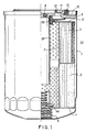
- the filter unit consists of a cup 1 into which two filter cartridges 2 and 3 respectively are inserted one above the other.
- the cartridge 2 is supported by a lower plate 4 supported by the base of the cup by way of a spring 5, whereas the upper cartridge 3 is kept pressed downwards by an upper plate 6 provided with a central hole.
- a perforated tube 7 extends centrally downwards from the plate 6.
- the plate 6 is pressed downwards by an elastic gasket 66 placed between the plate 6 and an upper plate 9 with a central threaded hole 8.
- the upper plate 9 is kept in position by an upper shaped over 10 which is clinched to the cup 1.
- the upper plate 9 and cover 10 comprises a series of circumferential holes 11 through which the oil arriving from the pump is fed into the filtering device. On entering through the holes 11 the oil flows into the interspace between the two filter cartridges 2 and 3 and the cup 1 and passes radially through said filter cartridges to flow into the central tube 7 and from here, through the threaded hole 8, to the engine lubrication duct.
- the filter cartridge 3 which is formed of fine porosity material
- a further concentric filter cartridge 33 formed of coarser porosity material, the porosity of the filter cartridge 2 being intermediate between that of the filter cartridge 3 and that of the filter cartridge 33.
- the cartridge 2 is preferably formed of paper with a porosity of between 10 and 30 microns
- the cartridge 3 is of paper with a porosity of between 4 and 15 microns
- the cartridge 33 is of non-woven fabric with a porosity of between 40 and 80 microns.
- the filter materials can generally be chosen from the following: paper-felt non-woven fabric, cotton, synthetic fibres, or glass fibres, either single, paired, plaited, rolled up or punched.
- a normal anti-emptying tube 99 extends from the centre of the plate 9, and a usual safety valve 44 is provided at the centre of the plate 4.
- the operation of the filter is such that the oil fed through the holes 11 reaches the interspace about said filter cartridges where it splits between the two cartridges, with the larger fraction passing through the filter cartridge of lesser resistance, ie the filter cartridge 2, until this latter is clogged to such an extent that the resistance to the passage of the oil to be filtered becomes comparable to that offered by the two cartridges 3 and 33 in series. At this point the oil begins to also traverse the pair of cartridges 3 and 33 to a substantial extent and thus undergo very fine filtration, which it is able to do until the filter is completely clogged.
- the presence of the coarse porosity filter cartridge 33 sufficiently delays complete clogging of the fine porosity filter 3 cartridge in the sense that it retains the larger size impurities and makes the filter life acceptable.
Landscapes
- Chemical & Material Sciences (AREA)
- Chemical Kinetics & Catalysis (AREA)
- Lubrication Details And Ventilation Of Internal Combustion Engines (AREA)
- Orthopedics, Nursing, And Contraception (AREA)
- Filtration Of Liquid (AREA)
- Fats And Perfumes (AREA)
- Infusion, Injection, And Reservoir Apparatuses (AREA)
Abstract
Description
- This industrial invention patent relates to a disposable unit for filtering lubricating oil in internal combustion engines, in particular in diesel engines. For filtering the lubricating oil in such engines, disposable filter units are known consisting of a cup-shaped container containing one or more filter cartridges, which is arranged to be screwed directly onto the engine block to receive the oil to be filtered from the lubricating oil pump and feed it to the various lubrication points provided in the engine.
- The most simple filters of this type are so-called full-flow filters, ie filters containing a single oil cartridge which is traversed by the whole throughput made available by the lubricating oil pump, and which feeds all the filtered oil to the lubricating points provided in the engine. These filters have operational limitations deriving from their intrinsic method of operation. In this respect, the filtering efficiency of said filters depends on the filter area and on the porosity of the filter material, whereas their life is inversely proportional to this porosity.
- Thus to obtain a filter having an acceptable life, large-surface medium-porosity filter cartridges must be used but these have the defect of a low initial filtering efficiency which increases proportionally with time until they are completely clogged. On the other hand, reducing the filter material porosity leads to a shortening of the filter life and requires a too high lubricating oil pump power, whereas increasing the porosity on the one hand increases the filter life by delaying its complete clogging but on the other hand means a too low filtering efficiency during the initial operating period of the filter.
- To obviate these drawbacks, which are obviously the result of a compromise between the requirement of engine protection on the one hand and economy and small overall size of the filter unit on the other hand, so-called double filtration units have been used. These latter filters, which are also known as mixed-circuit filters, provide a better filtration than that obtainable with the aforesaid full-flow filters. They consist of a casing housing two filter cartridges arranged in parallel to receive the oil to be filtered from one and the same compartment, but feed the filtered oil to two different destinations. Specifically, the larger filter cartridge, which is also that of coarser porosity, feeds the filtered oil directly to the engine users, whereas the smaller filter cartridge of finer porosity, used for the so-called fine filtering, feeds the oil directly into the engine sump through separate ducts. Thus most of the oil passes through the coarser porosity filter cartridge to be fed to the lubricating points provided in the engine, whereas a smaller fraction of the oil is recycled to the sump with all impurities completely removed. Statistically, this continuous mixing in the engine sump of a small throughput of highly filtered oil with a larger throughput of normally filtered oil greatly increases the average degree of oil filtration.
- This type of filter, known as a mixed-circuit filter, has however the serious drawback that it can be fitted only to engines designed for this purpose. In this respect, at the point where the filter unit is screwed on, there must be a duct provided for recirculation directly into the sump, a feed duct to the various lubrication points and a duct for oil feed to the filter. These filters cannot therefore be applied to engines which do not possess a circuit for recirculating part of the oil directly to the engine sump. To obtain the same filtering efficiency without too much complication in engines not designed for mixed-circuit filters, an attempt has been made to fit into one and the same filter unit two cartridges of different porosity operating in parallel and feeding into the same lubrication circuit feed duct. However, this attempt has proved ineffective because the filter cartridge of finer porosity is the first to clog and after a certain period of operation becomes completely inefficient, making the entire unit ineffective.
- The object of the present invention is to provide a filter unit which combines the efficiency of mixed-circuit filter units with the simplicity of application of full-flow filter units, and which can be applied both to engines designed to receive full-flow filter units and to engines designed to receive mixed-circuit filter units.
- This is attained by a filter unit using two filter cartridges of different porosity operating in parallel, of which at last one, that of smaller filtering area and finer porosity, is arranged in series with and downstream of a third filter cartridge of coarser porosity.
- The merits and constructional and operational characteristics of the invention will be more apparent from the detailed description given hereinafter with reference to the figures of the accompanying drawing which illustrate a preferred embodiment of the invention by way of non-limiting example.
- Figure 1 shows a filter unit according to the invention in partial section; and
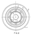
- Figure 2 is a plan view thereof.
- From said figures it can be seen that the filter unit consists of a cup 1 into which two
filter cartridges cartridge 2 is supported by a lower plate 4 supported by the base of the cup by way of a spring 5, whereas theupper cartridge 3 is kept pressed downwards by anupper plate 6 provided with a central hole. A perforated tube 7 extends centrally downwards from theplate 6. Theplate 6 is pressed downwards by anelastic gasket 66 placed between theplate 6 and anupper plate 9 with a central threadedhole 8. Theupper plate 9 is kept in position by an upper shaped over 10 which is clinched to the cup 1. In addition to the central threaded hole, theupper plate 9 andcover 10 comprises a series ofcircumferential holes 11 through which the oil arriving from the pump is fed into the filtering device. On entering through theholes 11 the oil flows into the interspace between the twofilter cartridges hole 8, to the engine lubrication duct. According to the invention, about thefilter cartridge 3, which is formed of fine porosity material, there is disposed a furtherconcentric filter cartridge 33 formed of coarser porosity material, the porosity of thefilter cartridge 2 being intermediate between that of thefilter cartridge 3 and that of thefilter cartridge 33. - By way of example, the
cartridge 2 is preferably formed of paper with a porosity of between 10 and 30 microns, and thecartridge 3 is of paper with a porosity of between 4 and 15 microns, whereas thecartridge 33 is of non-woven fabric with a porosity of between 40 and 80 microns. The filter materials can generally be chosen from the following: paper-felt non-woven fabric, cotton, synthetic fibres, or glass fibres, either single, paired, plaited, rolled up or punched. - A normal
anti-emptying tube 99 extends from the centre of theplate 9, and ausual safety valve 44 is provided at the centre of the plate 4. - The operation of the filter is such that the oil fed through the
holes 11 reaches the interspace about said filter cartridges where it splits between the two cartridges, with the larger fraction passing through the filter cartridge of lesser resistance, ie thefilter cartridge 2, until this latter is clogged to such an extent that the resistance to the passage of the oil to be filtered becomes comparable to that offered by the twocartridges cartridges - It will be noted that with the described configuration, the mixing of a flow of oil undergoing medium filtration with a smaller flow of oil undergoing fine filtration is statistically obtained directly within the filter unit instead of within the engine sump as happens in the case of normal mixed circuit filters.
- The presence of the coarse
porosity filter cartridge 33 sufficiently delays complete clogging of thefine porosity filter 3 cartridge in the sense that it retains the larger size impurities and makes the filter life acceptable. - It will also be noted that above the
shaped cover 10 there are located the seats of twoannular gaskets gasket 12. These ducts are thus excluded from the oil circuit with the result that the filter unit heretofore described an be applied both to engine blocks designed for full-flow filter units and to engine blocks designed for mixed-circuit filter units. - The invention is not limited to the embodiments heretofore described and modifications and improvements can be made thereto but without leaving the scope of the invention, the basic characteristics of which are summarised in the following claims.
Claims (5)
Priority Applications (1)
| Application Number | Priority Date | Filing Date | Title |
|---|---|---|---|
| AT88202701T ATE101802T1 (en) | 1988-05-10 | 1988-11-28 | DISPOSABLE TRIPLE FILTRATION FILTERS. |
Applications Claiming Priority (2)
| Application Number | Priority Date | Filing Date | Title |
|---|---|---|---|
| IT4684588 | 1988-05-10 | ||
| IT8846845A IT8846845A0 (en) | 1988-05-10 | 1988-05-10 | DISPOSABLE FILTERING UNIT FOR TRIPLE FILTRATION OIL |
Publications (3)
| Publication Number | Publication Date |
|---|---|
| EP0341349A2 true EP0341349A2 (en) | 1989-11-15 |
| EP0341349A3 EP0341349A3 (en) | 1990-06-20 |
| EP0341349B1 EP0341349B1 (en) | 1994-02-23 |
Family
ID=11259591
Family Applications (1)
| Application Number | Title | Priority Date | Filing Date |
|---|---|---|---|
| EP88202701A Expired - Lifetime EP0341349B1 (en) | 1988-05-10 | 1988-11-28 | Disposable oil filter unit with triple filtration |
Country Status (7)
| Country | Link |
|---|---|
| US (1) | US4950400A (en) |
| EP (1) | EP0341349B1 (en) |
| JP (1) | JPH08167B2 (en) |
| AT (1) | ATE101802T1 (en) |
| DE (1) | DE3887982T2 (en) |
| ES (1) | ES2050699T3 (en) |
| IT (1) | IT8846845A0 (en) |
Cited By (10)
| Publication number | Priority date | Publication date | Assignee | Title |
|---|---|---|---|---|
| EP0487231A3 (en) * | 1990-11-20 | 1993-04-28 | Mitsubishi Oil Company, Limited | Oil filter |
| EP0793990A2 (en) | 1996-03-06 | 1997-09-10 | UFI Universal Filter International S.p.A. | Process for manufacturing a filter medium, the medium manufactured thereby, and filters using said medium |
| EP1070529A1 (en) * | 1999-07-19 | 2001-01-24 | Stanadyne Automotive Corp. | Fuel filter cartridge |
| WO2001060495A1 (en) * | 2000-02-19 | 2001-08-23 | Alan Philip Roper | Dual flow filter |
| WO2002036235A1 (en) * | 2000-11-06 | 2002-05-10 | Jun Liu | Housing of an oil filter |
| EP1275427A3 (en) * | 2001-07-11 | 2003-03-12 | Water Creations, Inc. | Multi-stage filter |
| EP1598101A1 (en) * | 2004-05-13 | 2005-11-23 | Baldwin Filters, Inc. | Fluid filtration apparatus and method |
| US7615146B2 (en) * | 2000-07-25 | 2009-11-10 | Davco Technology, Llc | Fluid filter with restrictive filter media for pressure relief |
| WO2011110952A1 (en) * | 2010-12-20 | 2011-09-15 | Ufi Innovation Center S.R.L. | A method for dimensioning a filter group for internal combustion engines and a relative filter group |
| CN108704355A (en) * | 2017-12-20 | 2018-10-26 | 新阳硅密(上海)半导体技术有限公司 | Photoresist filter |
Families Citing this family (23)
| Publication number | Priority date | Publication date | Assignee | Title |
|---|---|---|---|---|
| US5186829A (en) * | 1991-08-16 | 1993-02-16 | Stanadyne Automotive Corp. | Fuel filter key system |
| US5308508A (en) * | 1992-05-15 | 1994-05-03 | Womack International, Inc. | High capacity filter media, method of use in filtration and method of formation |
| DE9305442U1 (en) * | 1993-04-14 | 1993-07-08 | Regeltechnik Friedrichshafen GmbH, 7990 Friedrichshafen | filter |
| UA23039C2 (en) * | 1994-03-02 | 1998-06-30 | Полтавське Наукове-Технічне Підприємство "Колаh" | filter for oil cleaning |
| US5630956A (en) * | 1995-06-20 | 1997-05-20 | Certified Technologies Corporation | Oil filtering and refining device |
| US5772881A (en) * | 1996-11-08 | 1998-06-30 | Champion Laboratories, Inc. | Non-metallic spin-on filter |
| AU3647199A (en) * | 1998-04-15 | 1999-11-01 | Porous Media Corporation | Stacked conical filtration or separation apparatus |
| US6478958B1 (en) * | 2000-01-19 | 2002-11-12 | Baldwin Filters, Inc. | Apparatus for filtering impurities out of fluid |
| US6610198B1 (en) | 2001-08-22 | 2003-08-26 | Fleetguard, Inc. | Liquid filter with change interval indicator |
| US6641742B2 (en) | 2001-08-22 | 2003-11-04 | Fleetguard, Inc. | Liquid filter with separate and calibrated vapor release |
| US6962660B2 (en) * | 2002-09-25 | 2005-11-08 | Master Spas, Inc. | Fluid filter system with secondary flow path for augmented filtration |
| US7329342B2 (en) * | 2004-11-15 | 2008-02-12 | Faria Manuel S | Metallic particle trap bypass filter |
| US20060102534A1 (en) * | 2004-11-15 | 2006-05-18 | Faria Manuel S | Bypass filter assembly |
| US20060151376A1 (en) * | 2004-12-23 | 2006-07-13 | Tubbs R W | Water filter apparatus |
| US8293103B2 (en) | 2005-12-08 | 2012-10-23 | Donaldson Company, Inc. | Spin-on filter assembly and methods |
| WO2009036042A1 (en) * | 2007-09-11 | 2009-03-19 | Ntz Micro Filtration Usa, Inc. | Improved manifold and filtration system |
| US20100006483A1 (en) * | 2008-07-10 | 2010-01-14 | Ravi Yekula | Replaceable filter elements including unique pressure relief and systems including same |
| US8375917B1 (en) * | 2009-07-23 | 2013-02-19 | Gene Neal | Engine oil cooler |
| JP5639615B2 (en) * | 2011-11-07 | 2014-12-10 | トヨタ紡織株式会社 | Oil deterioration control device |
| JP5677268B2 (en) | 2011-11-07 | 2015-02-25 | トヨタ紡織株式会社 | Oil deterioration control device |
| JP6057541B2 (en) | 2012-05-07 | 2017-01-11 | トヨタ紡織株式会社 | Oil deterioration control device |
| WO2014133836A1 (en) * | 2013-02-28 | 2014-09-04 | United Technologies Corporation | Self cleaning debris filter for fan drive gear system |
| CN204261451U (en) * | 2014-11-14 | 2015-04-15 | 天纳克(苏州)排放系统有限公司 | Filter |
Family Cites Families (8)
| Publication number | Priority date | Publication date | Assignee | Title |
|---|---|---|---|---|
| GB826114A (en) * | 1957-05-27 | 1959-12-23 | Erika Seidler | Improvements in or relating to filters |
| FR1407307A (en) * | 1963-07-26 | 1965-07-30 | Winslow Engineering And Mfg Co | Filter for filtering the lubricating oil of an internal combustion engine |
| GB1124735A (en) * | 1966-07-23 | 1968-08-21 | Stone Filter Company Inc | Improvements relating to filters |
| FR1524599A (en) * | 1967-05-25 | 1968-05-10 | Gen Motors Ltd | Liquid filtering device especially for internal combustion engine |
| GB1604832A (en) * | 1978-05-31 | 1981-12-16 | Fram Corp | Apparatus for filtering fluids |
| JPS61111113A (en) * | 1984-11-02 | 1986-05-29 | Orijin:Kk | Lubricating oil filter |
| SU1337536A1 (en) * | 1985-12-06 | 1987-09-15 | Кузбасский Политехнический Институт | Full-flow oil filter for internal combustion engine |
| IT1192015B (en) * | 1986-06-27 | 1988-03-31 | Tecnocar Spa | FILTER FOR INTERNAL COMBUSTION ENGINE LUBRICANTS WITH RESERVE OF ADDITIVES |
-
1988
- 1988-05-10 IT IT8846845A patent/IT8846845A0/en unknown
- 1988-11-28 ES ES88202701T patent/ES2050699T3/en not_active Expired - Lifetime
- 1988-11-28 DE DE3887982T patent/DE3887982T2/en not_active Expired - Lifetime
- 1988-11-28 AT AT88202701T patent/ATE101802T1/en not_active IP Right Cessation
- 1988-11-28 EP EP88202701A patent/EP0341349B1/en not_active Expired - Lifetime
-
1989
- 1989-03-10 JP JP1056546A patent/JPH08167B2/en not_active Expired - Lifetime
- 1989-03-24 US US07/329,412 patent/US4950400A/en not_active Expired - Lifetime
Cited By (16)
| Publication number | Priority date | Publication date | Assignee | Title |
|---|---|---|---|---|
| EP0487231A3 (en) * | 1990-11-20 | 1993-04-28 | Mitsubishi Oil Company, Limited | Oil filter |
| US6283307B1 (en) | 1996-03-06 | 2001-09-04 | Ufi Universal Filter Intenational S.P.A. | Filter medium and filter cartridge |
| EP0793990A2 (en) | 1996-03-06 | 1997-09-10 | UFI Universal Filter International S.p.A. | Process for manufacturing a filter medium, the medium manufactured thereby, and filters using said medium |
| EP1070529A1 (en) * | 1999-07-19 | 2001-01-24 | Stanadyne Automotive Corp. | Fuel filter cartridge |
| US6893555B2 (en) * | 2000-02-19 | 2005-05-17 | Alan Philip Roper | Dual flow filter |
| WO2001060495A1 (en) * | 2000-02-19 | 2001-08-23 | Alan Philip Roper | Dual flow filter |
| US7615146B2 (en) * | 2000-07-25 | 2009-11-10 | Davco Technology, Llc | Fluid filter with restrictive filter media for pressure relief |
| WO2002036235A1 (en) * | 2000-11-06 | 2002-05-10 | Jun Liu | Housing of an oil filter |
| EP1275427A3 (en) * | 2001-07-11 | 2003-03-12 | Water Creations, Inc. | Multi-stage filter |
| US6632352B2 (en) | 2001-07-11 | 2003-10-14 | Nursery Pro, Inc. | Multi-stage filter |
| EP1598101A1 (en) * | 2004-05-13 | 2005-11-23 | Baldwin Filters, Inc. | Fluid filtration apparatus and method |
| US9061222B2 (en) | 2004-05-13 | 2015-06-23 | Baldwin Filters, Inc. | Fluid filtration apparatus and method |
| US10112134B2 (en) | 2004-05-13 | 2018-10-30 | Baldwin Filters, Inc. | Fluid filtration apparatus and method |
| WO2011110952A1 (en) * | 2010-12-20 | 2011-09-15 | Ufi Innovation Center S.R.L. | A method for dimensioning a filter group for internal combustion engines and a relative filter group |
| ITRE20100099A1 (en) * | 2010-12-20 | 2012-06-21 | Ufi Innovation Ct Srl | DIMENSIONING METHOD OF A FILTERING UNIT FOR INTERNAL COMBUSTION ENGINES AND RELATED FILTER UNIT |
| CN108704355A (en) * | 2017-12-20 | 2018-10-26 | 新阳硅密(上海)半导体技术有限公司 | Photoresist filter |
Also Published As
| Publication number | Publication date |
|---|---|
| EP0341349B1 (en) | 1994-02-23 |
| JPH08167B2 (en) | 1996-01-10 |
| ES2050699T3 (en) | 1994-06-01 |
| DE3887982D1 (en) | 1994-03-31 |
| IT8846845A0 (en) | 1988-05-10 |
| HK1007115A1 (en) | 1999-04-01 |
| EP0341349A3 (en) | 1990-06-20 |
| DE3887982T2 (en) | 1994-07-14 |
| ATE101802T1 (en) | 1994-03-15 |
| US4950400A (en) | 1990-08-21 |
| JPH0214708A (en) | 1990-01-18 |
Similar Documents
| Publication | Publication Date | Title |
|---|---|---|
| US4950400A (en) | Disposable oil filter unit with triple filtration | |
| US4886599A (en) | Filter cartridge with series elements for chemical and mechanical filtration | |
| US3370708A (en) | Dual element, dual valve, twist-on type filter assembly | |
| US3726403A (en) | Dual flow, spin-on filter | |
| US3397786A (en) | Dual element filter assembly having plural valves therein | |
| US3235085A (en) | Filter unit having dual purpose valve assembly | |
| US3912631A (en) | Oil filter and adapter | |
| US4755289A (en) | Lubricant filter for internal combustion engines | |
| EP1399238B1 (en) | Hybrid spin-on filter | |
| US3586171A (en) | Combination dual-flow and two-stage filter | |
| RU2359736C2 (en) | Filter device for fluid medium and method of fluid medium filtering | |
| US4619764A (en) | Repelling-action filter unit and assembly | |
| US3802564A (en) | Oil filter and adapter | |
| US3297162A (en) | Fluid filter with extended service life | |
| US6177003B1 (en) | Filter with safety element for filtering engine oil | |
| EP0250861A2 (en) | A lubricant filter assembly and method for mounting the same | |
| US2422647A (en) | Filter | |
| US4456529A (en) | Filter device for diesel engines | |
| DE112015004116B4 (en) | Axial flow air filter element, filter system and filter system maintenance procedures | |
| US3229817A (en) | Assembly for separating immiscible fluids | |
| GB1023178A (en) | Improvements relating to filters | |
| US4601799A (en) | Electric field oil filter and method of filtering | |
| US3288299A (en) | Oil filter cartridge | |
| US3353680A (en) | Dual element parallel flow filter assembly | |
| KR100362759B1 (en) | Filters, especially fluid filters |
Legal Events
| Date | Code | Title | Description |
|---|---|---|---|
| PUAI | Public reference made under article 153(3) epc to a published international application that has entered the european phase |
Free format text: ORIGINAL CODE: 0009012 |
|
| AK | Designated contracting states |
Kind code of ref document: A2 Designated state(s): AT BE CH DE ES FR GB GR IT LI LU NL SE |
|
| PUAL | Search report despatched |
Free format text: ORIGINAL CODE: 0009013 |
|
| AK | Designated contracting states |
Kind code of ref document: A3 Designated state(s): AT BE CH DE ES FR GB GR IT LI LU NL SE |
|
| 17P | Request for examination filed |
Effective date: 19900807 |
|
| 17Q | First examination report despatched |
Effective date: 19910723 |
|
| GRAA | (expected) grant |
Free format text: ORIGINAL CODE: 0009210 |
|
| AK | Designated contracting states |
Kind code of ref document: B1 Designated state(s): AT BE CH DE ES FR GB GR IT LI LU NL SE |
|
| PG25 | Lapsed in a contracting state [announced via postgrant information from national office to epo] |
Ref country code: NL Effective date: 19940223 Ref country code: LI Effective date: 19940223 Ref country code: AT Effective date: 19940223 Ref country code: SE Effective date: 19940223 Ref country code: CH Effective date: 19940223 |
|
| REF | Corresponds to: |
Ref document number: 101802 Country of ref document: AT Date of ref document: 19940315 Kind code of ref document: T |
|
| ET | Fr: translation filed | ||
| REF | Corresponds to: |
Ref document number: 3887982 Country of ref document: DE Date of ref document: 19940331 |
|
| ITF | It: translation for a ep patent filed | ||
| REG | Reference to a national code |
Ref country code: CH Ref legal event code: PL |
|
| REG | Reference to a national code |
Ref country code: ES Ref legal event code: FG2A Ref document number: 2050699 Country of ref document: ES Kind code of ref document: T3 |
|
| REG | Reference to a national code |
Ref country code: GR Ref legal event code: FG4A Free format text: 3011770 |
|
| NLV1 | Nl: lapsed or annulled due to failure to fulfill the requirements of art. 29p and 29m of the patents act | ||
| PG25 | Lapsed in a contracting state [announced via postgrant information from national office to epo] |
Ref country code: LU Free format text: LAPSE BECAUSE OF NON-PAYMENT OF DUE FEES Effective date: 19941130 |
|
| PLBE | No opposition filed within time limit |
Free format text: ORIGINAL CODE: 0009261 |
|
| STAA | Information on the status of an ep patent application or granted ep patent |
Free format text: STATUS: NO OPPOSITION FILED WITHIN TIME LIMIT |
|
| 26N | No opposition filed | ||
| REG | Reference to a national code |
Ref country code: GB Ref legal event code: IF02 |
|
| PGFP | Annual fee paid to national office [announced via postgrant information from national office to epo] |
Ref country code: ES Payment date: 20071129 Year of fee payment: 20 |
|
| PGFP | Annual fee paid to national office [announced via postgrant information from national office to epo] |
Ref country code: IT Payment date: 20071127 Year of fee payment: 20 |
|
| PGFP | Annual fee paid to national office [announced via postgrant information from national office to epo] |
Ref country code: BE Payment date: 20071203 Year of fee payment: 20 |
|
| PGFP | Annual fee paid to national office [announced via postgrant information from national office to epo] |
Ref country code: GB Payment date: 20071115 Year of fee payment: 20 Ref country code: FR Payment date: 20071108 Year of fee payment: 20 |
|
| PGFP | Annual fee paid to national office [announced via postgrant information from national office to epo] |
Ref country code: GR Payment date: 20071108 Year of fee payment: 20 Ref country code: DE Payment date: 20080109 Year of fee payment: 20 |
|
| BE20 | Be: patent expired |
Owner name: *UNIVERSAL FILTER ITALIANA S.P.A. Effective date: 20081128 |
|
| REG | Reference to a national code |
Ref country code: GB Ref legal event code: PE20 Expiry date: 20081127 |
|
| REG | Reference to a national code |
Ref country code: ES Ref legal event code: FD2A Effective date: 20081129 |
|
| PG25 | Lapsed in a contracting state [announced via postgrant information from national office to epo] |
Ref country code: ES Free format text: LAPSE BECAUSE OF EXPIRATION OF PROTECTION Effective date: 20081129 |
|
| PG25 | Lapsed in a contracting state [announced via postgrant information from national office to epo] |
Ref country code: GB Free format text: LAPSE BECAUSE OF EXPIRATION OF PROTECTION Effective date: 20081127 |