EP0341306B1 - Accelerometer with isolator for common mode inputs - Google Patents
Accelerometer with isolator for common mode inputs Download PDFInfo
- Publication number
- EP0341306B1 EP0341306B1 EP89901226A EP89901226A EP0341306B1 EP 0341306 B1 EP0341306 B1 EP 0341306B1 EP 89901226 A EP89901226 A EP 89901226A EP 89901226 A EP89901226 A EP 89901226A EP 0341306 B1 EP0341306 B1 EP 0341306B1
- Authority
- EP
- European Patent Office
- Prior art keywords
- axis
- proof mass
- transducer
- isolator
- hinge axis
- Prior art date
- Legal status (The legal status is an assumption and is not a legal conclusion. Google has not performed a legal analysis and makes no representation as to the accuracy of the status listed.)
- Expired - Lifetime
Links
Images

Classifications
-
- G—PHYSICS
- G01—MEASURING; TESTING
- G01P—MEASURING LINEAR OR ANGULAR SPEED, ACCELERATION, DECELERATION, OR SHOCK; INDICATING PRESENCE, ABSENCE, OR DIRECTION, OF MOVEMENT
- G01P15/00—Measuring acceleration; Measuring deceleration; Measuring shock, i.e. sudden change of acceleration
- G01P15/02—Measuring acceleration; Measuring deceleration; Measuring shock, i.e. sudden change of acceleration by making use of inertia forces using solid seismic masses
- G01P15/08—Measuring acceleration; Measuring deceleration; Measuring shock, i.e. sudden change of acceleration by making use of inertia forces using solid seismic masses with conversion into electric or magnetic values
- G01P15/097—Measuring acceleration; Measuring deceleration; Measuring shock, i.e. sudden change of acceleration by making use of inertia forces using solid seismic masses with conversion into electric or magnetic values by vibratory elements
Definitions
- the present invention relates to accelerometers and, in particular, to an accelerometer in which movement of a proof mass is constrained by force transducers.
- a primary source of common mode errors in most vibrating beam accelerometers is related to mismatched coefficients of thermal expansion.
- Crystalline quartz in the crystalline axis orientation commonly used for force transducers, has a relatively nonlinear expansion coefficient as a function of temperature. It is extremely difficult to find metals with the proper qualities for flexures which also match the thermal expansion of crystalline quartz. Even if a perfect match were made at a given temperature, the nonlinearities of crystalline quartz expansion would cause mismatches to occur at the operating temperature extremes.
- the zero stress point of crystal attachment it is common for the zero stress point of crystal attachment to be at a temperature substantially above the accelerometer operating range. This is typical for epoxies, anodic bonding, brazing, and glass frit bonding. Thus the resulting accelerometer will have thermal expansion mismatch that will cause common mode stress on the crystals.
- the member which is mechanically isolated from the support and to which the force transducers are connected is referred to herein as an isolator.
- US-A-4658174 there is a disclosure of a mechanical isolator in a vibrating beam force transducer, but that is an isolator mass the function of which is to prevent the transfer of energy from the vibrating member of a resonator to a support. There is no equivalent of the suspension means of this invention.
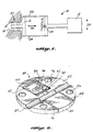
- the accelerometer 10 comprises proof mass 12 that is mounted to support 14 such that the proof mass is rotatable about hinge axis HA that is normal to the plane of the drawing.
- the accelerometer further comprises isolator 16 that is mounted to a different portion of support 14 by an isolator suspension system generally indicated by reference numeral 20.
- the isolator suspension system symbolized by four rollers in FIGURE 1, is compliant along a transducer axis TA that is perpendicular to sensitive axis SA and to hinge axis HA, and is noncompliant for rotation about hinge axis HA.
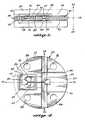
- Isolator 42 is formed by making a pair of interlocking C-shaped slots 54 and 56, the slots resulting in the formation of isolator 42 connected to support 52 by beams 60 and 62.
- the sizes and positions of slots 54 and 56 are adjusted such that beams 60 and 62 have comparatively small dimensions along a transducer axis TA, and comparatively large dimensions along the hinge axis and sensitive axis.
- isolator 42 is relatively compliant for translational motion along the transducer axis, and is comparatively noncompliant for other degrees of freedom, including rotation about hinge axis HA.
- the upper and lower surfaces of isolator 42 include cutout sections 70 and 72 that are provided to reduce the mass of the isolator, for reasons discussed below.
- the upper surfaces of isolator 42, beam 62 and support 52 include recessed areas 74, 76 and 78, respectively, and the lower surfaces of the corresponding elements include similar recessed sections. These recessed sections permit attachment of force sensing crystals 80 and 82 between isolator 42 and proof mass 40.
- Upper support 30, proof mass assembly 34 and lower support 32 are fastened together by four screws (not shown) that pass through openings (not shown) in the upper and lower plates, and through openings 86 in support 52.
- the upper and lower plates include recessed areas 88 above and below the force sensing crystals, to accommodate the crystals and the lead wires connected thereto.
- the crystals could also be mounted on pedestals, or recessed into the proof mass assembly to adjust scaling and natural frequency.
- the portions of the upper and lower plates adjacent to proof mass 40 may be machined such that these surfaces are set slightly back from the proof mass, to provide suitable shock clearances at interfaces 90 between the proof mass and the adjacent surfaces of the upper and lower plates.
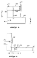
- FIGURE 6 A second embodiment of the accelerometer of the present invention is illustrated schematically in FIGURE 6.
- proof mass 150 is mounted to a support by suitable means (not shown) such that the proof mass can rotate about hinge axis HA that is normal to the plane of the drawing in FIGURE 6.
- Isolator 152 is mounted to support 154 by an isolator suspension system illustrated as a pair of flexures 156, such that isolator 152 is relatively compliant for translational movement along a transducer axis TA that for this embodiment is parallel to sensitive axis SA.
- flexures 156 prevent rotation of isolator 152 about hinge axis HA.
- a pair of force sensing crystals 160 and 162 extend between proof mass 150 and isolator 152, parallel to transducer axis TA.
- acceleration along sensitive axis SA tends to rotate proof mass 150 about hinge axis HA, thereby putting one force sensing crystal in tension and the other force sensing crystal in compression.
- differential thermal expansion or contraction of the force sensing crystals with respect to the other accelerometer components causes translational movement of isolator 152 along transducer axis TA. Because of the high compliance of the isolator along the transducer axis, differential thermal expansion causes a relatively small common mode force on the crystals.
- Force sensing crystals 176 and 178 extend along transducer axis TA between proof mass 170 and isolator 174, on opposite sides of hinge axis HA.
- Transducer axis TA is perpendicular to both the hinge axis and to sensitive axis SA.
- acceleration along sensitive axis SA tends to rotate proof mass 170 about hinge axis HA, thereby putting one force sensing crystal in tension and the other in compression.
- differential thermal expansion of the force sensing crystals tends to rotate isolator 174 about pivot axis 176, producing a small common mode force on the crystals.
- the mass of isolator 42 and the nonlinearities in the crystals lead to a slight cross axis acceleration sensitivity, even though the loading is common mode.
- One way to reduce this error source is to reduce the mass of the isolator as much as possible, such as by means of recesses 70 and 72.
- Another option is to use an accelerometer such as the one shown in FIGURE 6, wherein the mass of isolator 152 adds common mode loading only due to sensitive axis acceleration. In this case, the error is removed by the calibration process for the accelerometer.
- Another option is to use an accelerometer such as the one shown in FIGURE 7, wherein isolator 174 is supported at its center of mass, so that it is uneffected by linear acceleration.
- connection of two vibrating beam force transducers to a single proof mass introduces a potential problem of crosstalk between the transducers.
- force sensing crystals that have center frequencies that are spaced far enough apart so that the frequency operating ranges of the crystals do not overlap.
- the use of crystals having different center frequencies can mean that the stiffnesses of the crystals will be different from one another, and that the forces sensed by the crystals for a given acceleration input will be different from one another.
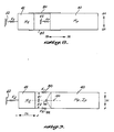
- FIGURE 9 A simplified model for the accelerometer of FIGURES 2-4 is presented in FIGURE 9.
- the model of FIGURE 9 includes proof mass 40 having moment of inertia I P about hinge axis HA, isolator 42 having mass M I , and isolation suspension system 20 that has a spring constant K I along transducer axis TA.
- F2 -K2 ( ⁇ ⁇ R2 + Z)
- ⁇ is the angle of rotation of the proof mass about the hinge axis
- Z is the distance of movement of the isolator along the transducer axis
- forces F1 and F2 are equal for any given acceleration input, i.e., for any given rotation of proof mass 10.
- F1 and F2 will be unequal due to differences between K1 and K2 and/or differences between R1 and R2 .
- K1 M I I P K1R 1 2 + K2R 2 2
- K1 spring constant K1
- K1 M I I P K1R 1 2 + K2R 2 2
- the value of K1 determined by Equation (3) is the tuned condition at which the resonant frequency of the isolator mass and isolator suspension system absent crystals 80 and 82 is the same as the fundamental system resonance, i.e., the resonant frequency of the proof mass and the force sensing crystals, assuming no isolator movement.
- isolator movement will tend to reduce the force differences between the crystals, and will therefore improve the vibration rectification coefficient.
- the isolator suspension system is therefore preferably designed such that K1 satisfies Equation (3), particularly for systems in which crystals having different center frequencies are used.
Landscapes
- Physics & Mathematics (AREA)
- General Physics & Mathematics (AREA)
- Pressure Sensors (AREA)
- Manipulator (AREA)
- Measurement Of Mechanical Vibrations Or Ultrasonic Waves (AREA)
Abstract
Description
- The present invention relates to accelerometers and, in particular, to an accelerometer in which movement of a proof mass is constrained by force transducers.
- In a vibrating beam accelerometer, a proof mass is mounted to a support by a flexure hinge or the like, and a vibrating beam force transducer is connected along the accelerometer's sensitive axis between the proof mass and the support. An acceleration along the sensitive axis results in a compression or tension force on the force transducer. This force is converted into an electrical signal that indicates both the direction and magnitude of the acceleration. A well-known type of vibrating beam force transducer comprises a quartz crystal arranged as a double-ended tuning fork. The double-ended tuning fork includes a pair of side-by-side beams that are caused to vibrate in a transverse oscillation mode in which the two beams move in their
common plane 180° out of phase with one another. Tension or compression forces on the force transducer result in an increase or decrease respectively of the vibration frequency. - Vibrating beam accelerometers possess a number of significant advantages, including excellent scale factor stability. Many error sources in such accelerometers can be greatly reduced by using two proof masses and two sensing crystals operated in a push-pull configuration, such that one crystal is put in compression while the other is put in tension. The output is treated as some function of the frequency difference. This method of measurement cancels out many common mode errors, including the contribution of force crystal nonlinearity to the vibration rectification coefficient. However, a disadvantage of using dual proof masses is that identity of the dynamic responses of the two accelerometers is difficult to achieve. To avoid these problems, it has previously been proposed to use a single proof mass in connection with a pair of force transducers, with the force transducers being connected to the proof mass in the push-pull mode in which one crystal is placed in tension and the other in compression for a given input acceleration. As with the dual proof mass approach, this arrangement may be used to cancel various common mode errors.
- A primary source of common mode errors in most vibrating beam accelerometers is related to mismatched coefficients of thermal expansion. Crystalline quartz, in the crystalline axis orientation commonly used for force transducers, has a relatively nonlinear expansion coefficient as a function of temperature. It is extremely difficult to find metals with the proper qualities for flexures which also match the thermal expansion of crystalline quartz. Even if a perfect match were made at a given temperature, the nonlinearities of crystalline quartz expansion would cause mismatches to occur at the operating temperature extremes. Furthermore, it is common for the zero stress point of crystal attachment to be at a temperature substantially above the accelerometer operating range. This is typical for epoxies, anodic bonding, brazing, and glass frit bonding. Thus the resulting accelerometer will have thermal expansion mismatch that will cause common mode stress on the crystals.
- Residual stresses on the crystals and mechanism can cause many problems. These problems include high bond line stresses on the end attachment joint, stress on mechanical parts, and stress on crystals. The high bond line stress results in accelerated creep, higher strength requirements, and limitations on usable bonding technologies. Stress on mechanism parts results in reduced shock load capability, dimensional instability, and additional strength requirements. Stress on the crystals results in dimensional instablities, reduced full range capability, changes in crystal operating points, higher temperature sensitivities, and differential mode errors due to unequal stiffness.
- It is an object of the invention to reduce common mode loading of the force transducers while maintaining high stiffness to support differential mode acceleration inputs.
- The invention as claimed provides an accelerometer for measuring acceleration along a sensitive axis (SA), the accelerometer comprising: a support; a proof mass; mounting means for mounting the proof mass to the support for pivotal movement about a hinge axis (HA) perpendicular to the sensitive axis (SA), and two force transducers connected between the proof mass and a member mechanically isolated from the support, the force transducers being parallel to a transducer axis (TA) normal to the hinge axis (HA) and being positioned on opposite sides of the hinge axis (HA) from one another such that pivotal movement of the proof mass about the hinge axis puts one force transducer in tension and the other force transducer in compression, characterised in that the means mechanically isolating the member from the support comprises suspension means which is relatively compliant for movement of the member parallel to the transducer axis and relatively noncompliant for pivotal movement of the member about the hinge axis.
- The member which is mechanically isolated from the support and to which the force transducers are connected is referred to herein as an isolator. In US-A-4658174 there is a disclosure of a mechanical isolator in a vibrating beam force transducer, but that is an isolator mass the function of which is to prevent the transfer of energy from the vibrating member of a resonator to a support. There is no equivalent of the suspension means of this invention.
-
- FIGURE 1 is a schematic drawing showing one preferred embodiment of the accelerometer of the present invention;
- FIGURE 2 is a perspective view of a proof mass assembly for an embodiment corresponding to FIGURE 1;
- FIGURE 3 is a cross-sectional view of an accelerometer corresponding to the proof mass assembly of FIGURE 2;
- FIGURE 4 is a top plan view of the proof mass assembly of FIGURE 2 and one of the force crystals;
- FIGURES 5A-5C are schematic illustrations of alternate isolator suspension systems;
- FIGURE 6 is a schematic view of a second preferred embodiment of the invention;
- FIGURE 7 is a schematic view of a third preferred embodiment of the present invention; and
- FIGURES 8 and 9 are schematic views of the accelerometer of FIGURES 2-4.
- One preferred embodiment of the accelerometer of the present invention is illustrated in schematic form in FIGURE 1. The
accelerometer 10 comprisesproof mass 12 that is mounted to support 14 such that the proof mass is rotatable about hinge axis HA that is normal to the plane of the drawing. The accelerometer further comprisesisolator 16 that is mounted to a different portion ofsuport 14 by an isolator suspension system generally indicated byreference numeral 20. The isolator suspension system, symbolized by four rollers in FIGURE 1, is compliant along a transducer axis TA that is perpendicular to sensitive axis SA and to hinge axis HA, and is noncompliant for rotation about hinge axis HA. -
Force transducers interconnect isolator 16 andproof mass 12. The force transducers are parallel to transducer axis TA, and are positioned on opposite sides of hinge axis HA from one another, such that rotation ofproof mass 12 about hinge axis HA puts one force transducer in tension and the other force transducer in compression. Differential thermal expansion or contraction offorce transducers isolator 16 along transducer axis TA, but ideally produces no stresses on the force transducers, and therefore does not result in errors in the accelerometer output. In a practical system in which the isolator suspension system has some small resistance to isolator movement along the transducer axis, the resulting small forces on the force transducers produce common mode inputs that are substantially cancelled by the push-pull arrangement of the transducers. - An actual embodiment corresponding to the schematic embodiment shown in FIGURE 1 is illustrated in FIGURES 2-4. This embodiment includes upper and
lower plates 30 and 32 (FIGURE 3) between whichproof mass assembly 34 is sandwiched.Proof mass assembly 34 comprises a cylindrical wafer in whichproof mass 40 andisolator 42 are formed.Force sensing crystals Proof mass 40 is formed by cuttingparallel slots circular arc flexure 50 betweenproof mass 40 and the remaining body of the proof mass assembly, hereafter designated assupport 52. The orientation of the hinge axis is such that it is perpendicular toslots proof mass 40. -
Isolator 42 is formed by making a pair of interlocking C-shaped slots isolator 42 connected to support 52 bybeams slots beams isolator 42 is relatively compliant for translational motion along the transducer axis, and is comparatively noncompliant for other degrees of freedom, including rotation about hinge axis HA. The upper and lower surfaces ofisolator 42 includecutout sections isolator 42,beam 62 andsupport 52 includerecessed areas force sensing crystals isolator 42 andproof mass 40. -
Upper support 30,proof mass assembly 34 andlower support 32 are fastened together by four screws (not shown) that pass through openings (not shown) in the upper and lower plates, and throughopenings 86 insupport 52. The upper and lower plates include recessedareas 88 above and below the force sensing crystals, to accommodate the crystals and the lead wires connected thereto. The crystals could also be mounted on pedestals, or recessed into the proof mass assembly to adjust scaling and natural frequency. The portions of the upper and lower plates adjacent toproof mass 40 may be machined such that these surfaces are set slightly back from the proof mass, to provide suitable shock clearances atinterfaces 90 between the proof mass and the adjacent surfaces of the upper and lower plates. - In operation,
force sensing crystals - The isolation system for
isolator 42 may take any form, so long as it provides for relatively high compliance for translation along transducer axis TA, and relatively low compliance for rotation about hinge axis HA. In addition, all isolator resonant frequencies are preferably kept well above the 2000 Hz maximum input vibration frequency. Three alternate isolator suspension systems are illustrated in FIGURES 5A-5C. In these figures,similar reference numerals isolator 42 is formed by a pair of opposed, nested C-shapedslots beams isolator 42 is formed by a pair of opposed C-shapedslots 110 and 112, and a pair oflinear slots 114 and 116, thereby forming a suspension system comprising beams 121-124. An advantage of the arrangement of FIGURE 5B is that it produces pure straight line motion of the isolator along the transducer axis. A disadvantage is that it involves more cuts (slots) than the embodiments shown in FIGURES 4 and 5A. Another arrangement for the isolator suspension system is shown in FIGURE 5C. In this embodiment, asingle slot 130 forms a nearly continuous rectangle, and enlarged ends 132 and 134 form aflexure 136. - A second embodiment of the accelerometer of the present invention is illustrated schematically in FIGURE 6. In this embodiment,
proof mass 150 is mounted to a support by suitable means (not shown) such that the proof mass can rotate about hinge axis HA that is normal to the plane of the drawing in FIGURE 6.Isolator 152 is mounted to support 154 by an isolator suspension system illustrated as a pair offlexures 156, such thatisolator 152 is relatively compliant for translational movement along a transducer axis TA that for this embodiment is parallel to sensitive axis SA. However,flexures 156 prevent rotation ofisolator 152 about hinge axis HA. A pair offorce sensing crystals proof mass 150 andisolator 152, parallel to transducer axis TA. As with the prior embodiments, acceleration along sensitive axis SA tends to rotateproof mass 150 about hinge axis HA, thereby putting one force sensing crystal in tension and the other force sensing crystal in compression. However, differential thermal expansion or contraction of the force sensing crystals with respect to the other accelerometer components causes translational movement ofisolator 152 along transducer axis TA. Because of the high compliance of the isolator along the transducer axis, differential thermal expansion causes a relatively small common mode force on the crystals. - A third embodiment of the invention is illustrated schematically in FIGURE 7. In this embodiment,
proof mass 170 is mounted to support 172 by suitable means, such that the proof mass is rotatable about hinge axis HA.Isolator 174 is also mounted to support 172 by suitable means, such that the isolator is rotatable aboutpivot axis 176 that is parallel to hinge axis HA, but displaced therefrom in a direction normal to the hinge axis, such that the isolator cannot rotate about the hinge axis.Pivot axis 176 preferably passes through the center of mass ofisolator 174, such that the isolator does not tend to rotate in response to acceleration inputs.Force sensing crystals proof mass 170 andisolator 174, on opposite sides of hinge axis HA. Transducer axis TA is perpendicular to both the hinge axis and to sensitive axis SA. As with prior embodiments, acceleration along sensitive axis SA tends to rotateproof mass 170 about hinge axis HA, thereby putting one force sensing crystal in tension and the other in compression. On the other hand, differential thermal expansion of the force sensing crystals tends to rotateisolator 174 aboutpivot axis 176, producing a small common mode force on the crystals. - In the embodiment shown in FIGURES 2-4, the mass of
isolator 42 and the nonlinearities in the crystals lead to a slight cross axis acceleration sensitivity, even though the loading is common mode. One way to reduce this error source is to reduce the mass of the isolator as much as possible, such as by means ofrecesses isolator 152 adds common mode loading only due to sensitive axis acceleration. In this case, the error is removed by the calibration process for the accelerometer. Another option is to use an accelerometer such as the one shown in FIGURE 7, whereinisolator 174 is supported at its center of mass, so that it is uneffected by linear acceleration. - Another approach to the isolator mass problem is schematically illustrated in FIGURE 8, wherein the reference numerals of FIGURES 2-4 are used again for convenience. MP and MI represent the masses of the proof mass and isolator, respectively. KP represents the spring constant for
flexure 50 for translational movement of the proof mass along the transducer axis with respect to the support. Similarly, KI represents the spring constant of the isolator suspension system, again for motion along the transducer axis with respect to the support. If the ratio MP/KP is made equal to MI/KI, then the cross axis sensitivity will go to zero. In general, the preferred way of achieving this equality is to make MI much smaller than MP, and KI much smaller than KP by the same factor. - The connection of two vibrating beam force transducers to a single proof mass introduces a potential problem of crosstalk between the transducers. Thus for some designs, it will be preferable to use force sensing crystals that have center frequencies that are spaced far enough apart so that the frequency operating ranges of the crystals do not overlap. The use of crystals having different center frequencies can mean that the stiffnesses of the crystals will be different from one another, and that the forces sensed by the crystals for a given acceleration input will be different from one another. This difference in the magnitudes of the sensed forces will in general lead to an increase in the vibration rectification coefficient, especially during the maximal proof mass excursions that accompany inputs at the fundamental system resonance, i.e., at the resonant frequency for vibration of the proof mass about the hinge axis with the isolator stationary.
- Another condition that will result in unequal forces being sensed by the crystals is if they are mounted at unequal perpendicular distances from the hinge axis, HA. This inequality can be a result of variations in the process used to attach the crystals to the mechanism and/or dimensional variations in the mechanism proper. These unequal mounting distances also increase the vibration rectification coefficient.
- The use of any isolator that can move along the transducer axis provides a means for reducing the vibration rectification coefficient, and this reduction can be maximized by the proper selection of the isolator stiffness along the transducer axis. A simplified model for the accelerometer of FIGURES 2-4 is presented in FIGURE 9. The model of FIGURE 9 includes
proof mass 40 having moment of inertia IP about hinge axis HA,isolator 42 having mass MI, andisolation suspension system 20 that has a spring constant KI along transducer axis TA. The isolator and proof mass are interconnected byforce sensing crystals centerline 180 that passes through hinge axis HA and is perpendicular to transducer axis TA. The system shown in FIGURE 9 can be thought of as a two degree of freedom system whose motions consist of proof mass rotation about the hinge axis and translation of the isolator along the transducer axis. For the present discussion, it will be assumed that the positive direction for proof mass rotation is clockwise, and that the positive direction for isolator movement is to the right. - In general, the forces F₁ and F₂ experienced by the respective force sensing crystals are given by


where ϑ is the angle of rotation of the proof mass about the hinge axis, Z is the distance of movement of the isolator along the transducer axis, and where it is assumed that a tension force is positive and a compression force is negative. Ideally, forces F₁ and F₂ are equal for any given acceleration input, i.e., for any given rotation ofproof mass 10. However in general, F₁ and F₂ will be unequal due to differences between K₁ and K₂ and/or differences between R₁ and R₂ . It has been found, however, that for the two degree of freedom model of FIGURE 9, the maximal difference between the forces experienced by the crystals during resonant proof mass excursions can be minimized by adjustment of spring constant K₁, such that
The value of K₁ determined by Equation (3) is the tuned condition at which the resonant frequency of the isolator mass and isolator suspension systemabsent crystals
Claims (10)
- An accelerometer for measuring acceleration along a sensitive axis (SA), the accelerometer comprising:
a support (14);
a proof mass (12);
mounting means for mounting the proof mass (12) to the support (14) for pivotal movement about a hinge axis (HA) perpendicular to the sensitive axis (SA), and
two force transducers (22, 24) connected between the proof mass (12) and a member (16) mechanically isolated from the support (14), the force ransducers (22, 24) being parallel to a transducer axis (TA) normal to the hinge axis (HA) and being positioned on opposite sides of the hinge axis (HA) from one another such that pivotal movement of the proof mass (12) about the hinge axis (HA) puts one force transducer (22) in tension and the other force transducer (24) in compression, CHARACTERISED IN THAT the means mechanically isolating the member (16) from the support (14) comprises suspension means (20) which is relatively compliant for movement of the member (16) parallel to the transducer axis and relatively noncompliant for pivotal movement of the member (16) about the hinge axis (HA). - An accelerometer according to claim 1, wherein the transducer axis (TA) is normal to the sensitive axis (SA).
- An accelerometer according to claim 2, wherein the suspension means (20) is relatively compliant for rotation of the member (16) about a pivot axis (136,176) parallel to the hinge axis (HA), but spaced from the hinge axis in a direction normal to the hinge axis.
- An accelerometer according to claim 1, wherein the transducer axis (TA) is parallel to the sensitive axis (SA).
- An accelerometer according to claim 1, wherein the suspension means (20) comprises first and second beams (60,62; 104,106; 121,122,123,124) positioned on opposite sides of the member (16) along the transducer axis (TA) , each beam extending in a direction parallel to the hinge axis (HA), each beam being connected to the support (14) and to the member (16), and each beam being relatively compliant to bending along the transducer axis (TA) and relatively noncompliant to bending along the sensitive axis (SA).
- An accelerometer according to claim 1, wherein the mounting means (20) comprises a circular arc flexure.
- An accelerometer according to any preceding claim, wherein the perpendicular distance (R₁) between each force transducer (80) and the hinge axis (HA) is equal to the perpendicular distance (R₂) between the other force transducer (82) and the hinge axis (HA) .
- An accelerometer according to any preceding claim, wherein the mass (Mp) of the proof mass (12) divided by the compliance (Kp) of the mounting means along the transducer axis TA is equal to the mass (MI) of the member (16) divided by the compliance (KI) of the suspension means (20) along the transducer axis.
- An accelerometer according to any preceding claim, wherein the spring constant of the suspension means (20) for movement of the member (16) along the transducer axis (TA) is selected such that the resonant frequency for vibration of the member (16) along the transducer axis (TA) independently of the force transducers and proof mass is substantially equal to the resonant frequency for proof mass vibration about the hinge axis (HA) with the member (16) held stationary.
- An accelerometer according to any preceding claim, wherein the support (14), proof mass (12), mounting means for the proof mass, member (16) and suspension means (20) together form a proof mass assembly (34) which is sandwiched between upper and lower plate members (30, 32) with the support (14) connected to the upper and lower plate members.
Applications Claiming Priority (2)
| Application Number | Priority Date | Filing Date | Title |
|---|---|---|---|
| US111984 | 1987-10-22 | ||
| US07/111,984 US4766768A (en) | 1987-10-22 | 1987-10-22 | Accelerometer with isolator for common mode inputs |
Publications (3)
| Publication Number | Publication Date |
|---|---|
| EP0341306A1 EP0341306A1 (en) | 1989-11-15 |
| EP0341306A4 EP0341306A4 (en) | 1991-05-08 |
| EP0341306B1 true EP0341306B1 (en) | 1993-02-24 |
Family
ID=22341504
Family Applications (1)
| Application Number | Title | Priority Date | Filing Date |
|---|---|---|---|
| EP89901226A Expired - Lifetime EP0341306B1 (en) | 1987-10-22 | 1988-10-10 | Accelerometer with isolator for common mode inputs |
Country Status (6)
| Country | Link |
|---|---|
| US (1) | US4766768A (en) |
| EP (1) | EP0341306B1 (en) |
| JP (1) | JPH0648277B2 (en) |
| DE (1) | DE3878683T2 (en) |
| IL (1) | IL87989A (en) |
| WO (1) | WO1989003998A1 (en) |
Families Citing this family (50)
| Publication number | Priority date | Publication date | Assignee | Title |
|---|---|---|---|---|
| US5274797A (en) * | 1986-05-30 | 1993-12-28 | Bull Hn Information Systems Inc. | Multiprocessor system with centralized initialization, testing and monitoring of the system and providing centralized timing |
| FR2627592B1 (en) * | 1988-02-22 | 1990-07-27 | Sagem | PENDULUM ACCELEROMETER NOT SERVED WITH RESONANT BEAM |
| US4872343A (en) * | 1988-08-10 | 1989-10-10 | Sundstrand Data Control, Inc. | Matched pairs of force transducers |
| US4945765A (en) * | 1988-08-31 | 1990-08-07 | Kearfott Guidance & Navigation Corp. | Silicon micromachined accelerometer |
| US4879914A (en) * | 1989-02-27 | 1989-11-14 | Sundstrand Data Control, Inc. | Unitary push-pull force transducer |
| US5165279A (en) * | 1989-07-06 | 1992-11-24 | Sundstrand Corporation | Monolithic accelerometer with flexurally mounted force transducer |
| FR2650895B1 (en) * | 1989-08-08 | 1991-10-11 | Onera (Off Nat Aerospatiale) | ACCELEROMETRIC SENSOR WITH BENDING VIBRATORS |
| US5058430A (en) * | 1989-12-29 | 1991-10-22 | Honeywell Inc. | Sensor capsule mounting |
| JP3142292B2 (en) * | 1990-06-11 | 2001-03-07 | サンドストランド・コーポレイション | Accelerometer with insulated flexure |
| CN1027011C (en) * | 1990-07-12 | 1994-12-14 | 涂相征 | Silicon beam piezoresistive acceleration sensor and manufacturing method thereof |
| WO1992003740A1 (en) * | 1990-08-17 | 1992-03-05 | Analog Devices, Inc. | Monolithic accelerometer |
| US5326726A (en) * | 1990-08-17 | 1994-07-05 | Analog Devices, Inc. | Method for fabricating monolithic chip containing integrated circuitry and suspended microstructure |
| US5314572A (en) * | 1990-08-17 | 1994-05-24 | Analog Devices, Inc. | Method for fabricating microstructures |
| US5417111A (en) * | 1990-08-17 | 1995-05-23 | Analog Devices, Inc. | Monolithic chip containing integrated circuitry and suspended microstructure |
| US5111694A (en) * | 1990-08-17 | 1992-05-12 | Sundstrand Corporation | Accelerometer with rebalance coil stress isolation |
| US5205171A (en) * | 1991-01-11 | 1993-04-27 | Northrop Corporation | Miniature silicon accelerometer and method |
| US5331853A (en) * | 1991-02-08 | 1994-07-26 | Alliedsignal Inc. | Micromachined rate and acceleration sensor |
| US5241861A (en) * | 1991-02-08 | 1993-09-07 | Sundstrand Corporation | Micromachined rate and acceleration sensor |
| US5243278A (en) * | 1991-02-08 | 1993-09-07 | Sundstrand Corporation | Differential angular velocity sensor that is sensitive in only one degree of freedom |
| US5396797A (en) * | 1991-02-08 | 1995-03-14 | Alliedsignal Inc. | Triaxial angular rate and acceleration sensor |
| US5168756A (en) * | 1991-02-08 | 1992-12-08 | Sundstrand Corporation | Dithering coriolis rate and acceleration sensor utilizing a permanent magnet |
| FR2685964B1 (en) * | 1992-01-06 | 1996-06-07 | Onera (Off Nat Aerospatiale) | MINIATURE ACCELEROMETRIC SENSOR WITH BENDING VIBRATING BLADES. |
| US5391844A (en) | 1992-04-03 | 1995-02-21 | Weigh-Tronix Inc | Load cell |
| US5442146A (en) | 1992-04-03 | 1995-08-15 | Weigh-Tronix, Inc. | Counting scale and load cell assembly therefor |
| US5336854A (en) | 1992-04-03 | 1994-08-09 | Weigh-Tronix, Inc. | Electronic force sensing load cell |
| US5313023A (en) | 1992-04-03 | 1994-05-17 | Weigh-Tronix, Inc. | Load cell |
| US5456110A (en) * | 1993-11-12 | 1995-10-10 | Alliedsignal Inc. | Dual pendulum vibrating beam accelerometer |
| US5594170A (en) * | 1994-06-15 | 1997-01-14 | Alliedsignal Inc. | Kip cancellation in a pendulous silicon accelerometer |
| EP0693690B1 (en) * | 1994-06-29 | 1999-04-28 | New Sd, Inc. | Accelerometer and method of manufacture |
| JP3114580B2 (en) * | 1995-08-24 | 2000-12-04 | 株式会社村田製作所 | Acceleration sensor |
| WO1997047977A1 (en) * | 1996-06-11 | 1997-12-18 | Alliedsignal Inc. | Compensation of second-order non-linearity in sensors employing double-ended tuning forks |
| US6723284B1 (en) * | 1997-04-11 | 2004-04-20 | University Of Pittsburgh | Membrane apparatus with enhanced mass transfer, heat transfer and pumping capabilities via active mixing |
| US6217826B1 (en) | 1997-04-11 | 2001-04-17 | University Of Pittsburgh | Membrane apparatus with enhanced mass transfer, heat transfer and pumping capabilities via active mixing |
| US6106776A (en) * | 1997-04-11 | 2000-08-22 | University Of Pittsburgh | Membrane apparatus with enhanced mass transfer via active mixing |
| US5905201A (en) * | 1997-10-28 | 1999-05-18 | Alliedsignal Inc. | Micromachined rate and acceleration sensor and method |
| US6351891B1 (en) | 1997-12-18 | 2002-03-05 | Honeywell International, Inc. | Miniature directional indication instrument |
| US6301965B1 (en) | 1999-12-14 | 2001-10-16 | Sandia Corporation | Microelectromechanical accelerometer with resonance-cancelling control circuit including an idle state |
| US6393913B1 (en) | 2000-02-08 | 2002-05-28 | Sandia Corporation | Microelectromechanical dual-mass resonator structure |
| WO2002043205A2 (en) * | 2000-10-31 | 2002-05-30 | Honeywell International Inc. | Suspension with net zero stress isolator |
| US6595056B2 (en) | 2001-02-07 | 2003-07-22 | Litton Systems, Inc | Micromachined silicon gyro using tuned accelerometer |
| US6474160B1 (en) | 2001-05-24 | 2002-11-05 | Northrop Grumman Corporation | Counterbalanced silicon tuned multiple accelerometer-gyro |
| US6619121B1 (en) | 2001-07-25 | 2003-09-16 | Northrop Grumman Corporation | Phase insensitive quadrature nulling method and apparatus for coriolis angular rate sensors |
| US6874363B1 (en) | 2003-10-31 | 2005-04-05 | Honeywell International, Inc. | Trapped charge field bias vibrating beam accelerometer |
| US7444883B2 (en) * | 2005-12-22 | 2008-11-04 | Honeywell International Inc. | Vibrating beam force transducer |
| US7467553B2 (en) * | 2005-12-22 | 2008-12-23 | Honeywell International Inc. | Capacitively coupled resonator drive |
| CN100397086C (en) * | 2007-07-09 | 2008-06-25 | 北京信息工程学院 | New Piezoelectric Quartz Accelerometer |
| US8499629B2 (en) * | 2008-10-10 | 2013-08-06 | Honeywell International Inc. | Mounting system for torsional suspension of a MEMS device |
| JP2012242343A (en) * | 2011-05-24 | 2012-12-10 | Seiko Epson Corp | Acceleration sensor and acceleration detector |
| US9164117B2 (en) * | 2012-10-19 | 2015-10-20 | Honeywell International Inc. | Stress reduction components for sensors |
| US10859596B2 (en) | 2018-07-20 | 2020-12-08 | Honeywell International Inc. | Mechanically-isolated in-plane pendulous vibrating beam accelerometer |
Family Cites Families (4)
| Publication number | Priority date | Publication date | Assignee | Title |
|---|---|---|---|---|
| US4221131A (en) * | 1979-05-29 | 1980-09-09 | The Singer Company | Vibrating beam accelerometer |
| US4517841A (en) * | 1983-01-06 | 1985-05-21 | Sundstrand Data Control, Inc. | Accelerometer with beam resonator force transducer |
| US4658174A (en) * | 1986-03-20 | 1987-04-14 | The Singer Company-Kearfott Division | Vibrating beam force transducer with angled isolator springs |
| US4718275A (en) * | 1986-06-27 | 1988-01-12 | Sundstrand Data Control, Inc. | Accelerometer with floating beam temperature compensation |
-
1987
- 1987-10-22 US US07/111,984 patent/US4766768A/en not_active Expired - Lifetime
-
1988
- 1988-10-10 DE DE8989901226T patent/DE3878683T2/en not_active Expired - Lifetime
- 1988-10-10 WO PCT/US1988/003486 patent/WO1989003998A1/en not_active Ceased
- 1988-10-10 IL IL87989A patent/IL87989A/en active Protection Beyond IP Right Term
- 1988-10-10 EP EP89901226A patent/EP0341306B1/en not_active Expired - Lifetime
- 1988-10-10 JP JP1501183A patent/JPH0648277B2/en not_active Expired - Lifetime
Also Published As
| Publication number | Publication date |
|---|---|
| DE3878683T2 (en) | 1993-06-09 |
| DE3878683D1 (en) | 1993-04-01 |
| EP0341306A1 (en) | 1989-11-15 |
| IL87989A (en) | 1991-12-15 |
| WO1989003998A1 (en) | 1989-05-05 |
| JPH01503414A (en) | 1989-11-16 |
| JPH0648277B2 (en) | 1994-06-22 |
| EP0341306A4 (en) | 1991-05-08 |
| US4766768A (en) | 1988-08-30 |
Similar Documents
| Publication | Publication Date | Title |
|---|---|---|
| EP0341306B1 (en) | Accelerometer with isolator for common mode inputs | |
| EP0419596B1 (en) | Accelerometer with coplanar push-pull force transducers | |
| EP0441910B1 (en) | Monolithic accelerometer with flexurally mounted force transducer | |
| US4872342A (en) | Translational accelerometer and accelerometer assembly method | |
| US5165279A (en) | Monolithic accelerometer with flexurally mounted force transducer | |
| US5020370A (en) | Vibrating beam force-frequency transducer and pendulous accelerator comprising application thereof | |
| US4299122A (en) | Force transducer | |
| US4656383A (en) | Vibrating beam force transducer with single isolator spring | |
| US4306456A (en) | Elastic wave accelerometer | |
| US5962786A (en) | Monolithic accelerometric transducer | |
| US6311556B1 (en) | Micro-accelerometer with capacitive resonator | |
| US4838369A (en) | Load cell having digital output | |
| JP2534721B2 (en) | Guaranteed mass suspension for accelerometers | |
| EP0270664B1 (en) | Temperature compensation of an accelerometer | |
| US5780742A (en) | Mechanical resonance, silicon accelerometer | |
| EP0052318A1 (en) | Force transducer | |
| US4446394A (en) | Linearizing mechanism for a vibrating beam force transducer | |
| US5574220A (en) | Vibrating beam force-frequency transducer | |
| US4599896A (en) | High accuracy accelerometer | |
| WO1988000352A1 (en) | Accelerometer with floating beam temperature compensation | |
| US20030188577A1 (en) | Isolated resonator gyroscope with isolation trimming using a secondary element | |
| EP0273048B1 (en) | Translational accelerometer | |
| US4703216A (en) | Oscillating crystal transducer systems | |
| GB2123953A (en) | Elastic surface wave accelerometers | |
| JPS62124462A (en) | Accelerometer with vibrating element |
Legal Events
| Date | Code | Title | Description |
|---|---|---|---|
| PUAI | Public reference made under article 153(3) epc to a published international application that has entered the european phase |
Free format text: ORIGINAL CODE: 0009012 |
|
| 17P | Request for examination filed |
Effective date: 19890703 |
|
| AK | Designated contracting states |
Kind code of ref document: A1 Designated state(s): CH DE FR GB LI NL SE |
|
| A4 | Supplementary search report drawn up and despatched |
Effective date: 19910322 |
|
| AK | Designated contracting states |
Kind code of ref document: A4 Designated state(s): CH DE FR GB LI NL SE |
|
| 17Q | First examination report despatched |
Effective date: 19920102 |
|
| RAP1 | Party data changed (applicant data changed or rights of an application transferred) |
Owner name: SUNDSTRAND CORPORATION |
|
| GRAA | (expected) grant |
Free format text: ORIGINAL CODE: 0009210 |
|
| AK | Designated contracting states |
Kind code of ref document: B1 Designated state(s): CH DE FR GB LI NL SE |
|
| PG25 | Lapsed in a contracting state [announced via postgrant information from national office to epo] |
Ref country code: SE Effective date: 19930224 Ref country code: NL Effective date: 19930224 |
|
| REF | Corresponds to: |
Ref document number: 3878683 Country of ref document: DE Date of ref document: 19930401 |
|
| ET | Fr: translation filed | ||
| NLV1 | Nl: lapsed or annulled due to failure to fulfill the requirements of art. 29p and 29m of the patents act | ||
| PLBE | No opposition filed within time limit |
Free format text: ORIGINAL CODE: 0009261 |
|
| STAA | Information on the status of an ep patent application or granted ep patent |
Free format text: STATUS: NO OPPOSITION FILED WITHIN TIME LIMIT |
|
| 26N | No opposition filed | ||
| REG | Reference to a national code |
Ref country code: GB Ref legal event code: 732E |
|
| REG | Reference to a national code |
Ref country code: GB Ref legal event code: IF02 |
|
| PGFP | Annual fee paid to national office [announced via postgrant information from national office to epo] |
Ref country code: GB Payment date: 20070918 Year of fee payment: 20 |
|
| PGFP | Annual fee paid to national office [announced via postgrant information from national office to epo] |
Ref country code: DE Payment date: 20071031 Year of fee payment: 20 |
|
| PGFP | Annual fee paid to national office [announced via postgrant information from national office to epo] |
Ref country code: CH Payment date: 20071009 Year of fee payment: 20 |
|
| PGFP | Annual fee paid to national office [announced via postgrant information from national office to epo] |
Ref country code: FR Payment date: 20071004 Year of fee payment: 20 |
|
| REG | Reference to a national code |
Ref country code: CH Ref legal event code: PL |
|
| REG | Reference to a national code |
Ref country code: GB Ref legal event code: PE20 Expiry date: 20081009 |
|
| PG25 | Lapsed in a contracting state [announced via postgrant information from national office to epo] |
Ref country code: GB Free format text: LAPSE BECAUSE OF EXPIRATION OF PROTECTION Effective date: 20081009 |