EP0341223A2 - Sharpening unit for leather splitting machines - Google Patents
Sharpening unit for leather splitting machines Download PDFInfo
- Publication number
- EP0341223A2 EP0341223A2 EP19890830190 EP89830190A EP0341223A2 EP 0341223 A2 EP0341223 A2 EP 0341223A2 EP 19890830190 EP19890830190 EP 19890830190 EP 89830190 A EP89830190 A EP 89830190A EP 0341223 A2 EP0341223 A2 EP 0341223A2
- Authority
- EP
- European Patent Office
- Prior art keywords
- grinding wheels
- sharpening unit
- carriage
- unit according
- pair
- Prior art date
- Legal status (The legal status is an assumption and is not a legal conclusion. Google has not performed a legal analysis and makes no representation as to the accuracy of the status listed.)
- Withdrawn
Links
- 239000010985 leather Substances 0.000 title claims abstract description 15
- 229910003460 diamond Inorganic materials 0.000 claims abstract description 13
- 239000010432 diamond Substances 0.000 claims abstract description 13
- 238000006073 displacement reaction Methods 0.000 description 4
- 239000003082 abrasive agent Substances 0.000 description 2
- 230000000694 effects Effects 0.000 description 1
- 239000000203 mixture Substances 0.000 description 1
- 230000004048 modification Effects 0.000 description 1
- 238000012986 modification Methods 0.000 description 1
Images

Classifications
-
- B—PERFORMING OPERATIONS; TRANSPORTING
- B24—GRINDING; POLISHING
- B24B—MACHINES, DEVICES, OR PROCESSES FOR GRINDING OR POLISHING; DRESSING OR CONDITIONING OF ABRADING SURFACES; FEEDING OF GRINDING, POLISHING, OR LAPPING AGENTS
- B24B3/00—Sharpening cutting edges, e.g. of tools; Accessories therefor, e.g. for holding the tools
- B24B3/36—Sharpening cutting edges, e.g. of tools; Accessories therefor, e.g. for holding the tools of cutting blades
- B24B3/368—Sharpening cutting edges, e.g. of tools; Accessories therefor, e.g. for holding the tools of cutting blades installed as an accessory on another machine
-
- B—PERFORMING OPERATIONS; TRANSPORTING
- B24—GRINDING; POLISHING
- B24B—MACHINES, DEVICES, OR PROCESSES FOR GRINDING OR POLISHING; DRESSING OR CONDITIONING OF ABRADING SURFACES; FEEDING OF GRINDING, POLISHING, OR LAPPING AGENTS
- B24B3/00—Sharpening cutting edges, e.g. of tools; Accessories therefor, e.g. for holding the tools
- B24B3/56—Sharpening cutting edges, e.g. of tools; Accessories therefor, e.g. for holding the tools of slicing bands
-
- Y—GENERAL TAGGING OF NEW TECHNOLOGICAL DEVELOPMENTS; GENERAL TAGGING OF CROSS-SECTIONAL TECHNOLOGIES SPANNING OVER SEVERAL SECTIONS OF THE IPC; TECHNICAL SUBJECTS COVERED BY FORMER USPC CROSS-REFERENCE ART COLLECTIONS [XRACs] AND DIGESTS
- Y10—TECHNICAL SUBJECTS COVERED BY FORMER USPC
- Y10T—TECHNICAL SUBJECTS COVERED BY FORMER US CLASSIFICATION
- Y10T83/00—Cutting
- Y10T83/303—With tool sharpener or smoother
- Y10T83/313—Spatially fixed tool
Definitions
- the band blade must be capable of operating in a very precise manner and consequently the cutting edge or bevel thereof must always be perfectly sharpened.
- a sharpening unit is provided to be mounted on splitting machines which unit must act continuously, during the machine operation, by means of a pair of grinding wheels symmetrically disposed relative to the blade bevel and in contact therewith.
- the main object of the present invention is to obviate the drawbacks associated with the splitting machines of the known art by providing a sharpening unit for leather splitting machines on which diamond grinding wheels can be mounted, which are capable of carrying out an identical and constant abrasive action both on the upper and lower parts of the cutting blade bevel.
- Shafts 8 and 9 are mounted, in a manner to be shown more clearly in the following, on a carriage 14 horizontally movable along guiding rods not shown in the figures and integral with the fixed casing of the splitting machine, from and towards the cutting blade 4. More particularly, the movable carriage 14 is formed with an upright portion 14a from which two substantially parallel arms 14b and 14c project, said arms supporting the shafts 8 and 9 and defining a space 15 through which the cutting blade 4 passes.
- locking means 76, 77 is associated with each of the adjusting handles 74, 75. It acts so as to lock the handle to predetermined angular positionings which can be individually selected according to requirements.
- said locking means 76, 77 preferably comprises, for each handle 74, 75, at least a movable plug 78, 79 slidably engaged through the corresponding handle 74, 75 and constantly submitted to the action of a spring 80, 81 tending to make it protrude from the handle itself at the lower part thereof.
Landscapes
- Engineering & Computer Science (AREA)
- Mechanical Engineering (AREA)
- Finish Polishing, Edge Sharpening, And Grinding By Specific Grinding Devices (AREA)
Abstract
The sharpening unit comprises two diamond grinding wheels (6, 7) mounted on respective shafts (8, 9) rotatably supported by a carriage (14) movable away from and towards the cutting blade (4) of a leather splitting machine to bring the grinding wheels (6, 7) in contact with the blade bevel. Said shafts (8, 9) are housed in eccentric bushes (30, 31) rotatably engaged in said carriage (14) and operable in angular rotation, which bushes can be fixed according to predetermined positions to give a desired mutual positioning to said diamond grinding wheels (6, 7).
Description
- The present invention relates to a sharpening unit for leather splitting machines.
- It is known that for carrying out the splitting of leather and the like, that is in order to perform a transverse cutting along leather sheets and separate a valuable layer having a constant thickness from a less valuable one to be discarded and corresponding to the reverse side of said sheets, particular machines referred to as splitting machines are used, which machines accomplish a leather thinning cut by means of band blades tautened between two pulleys or flywheels.
- Due to the fact that leathers to be split are usually very thin in thickness, the band blade must be capable of operating in a very precise manner and consequently the cutting edge or bevel thereof must always be perfectly sharpened. To achieve a perfect sharpening a sharpening unit is provided to be mounted on splitting machines which unit must act continuously, during the machine operation, by means of a pair of grinding wheels symmetrically disposed relative to the blade bevel and in contact therewith.
- Grinding wheels conventionally used on leather splitting machines consist of a mixture of abrasive materials with differently sized grains and must be provided with independent adjusting means designed to adjust their positioning in relation to the blade bevel. In greater detail the upper and lower grinding wheels are mounted on respective swinging arms provided with a projection in which a threaded through hole is bored. Operatively engaged with said hole is an adjusting screw the free end of which is designed to abut against a fixed locator element carried by the sharpening unit casing. In this manner, by acting upon one of the adjusting screws it is possible to move the swinging arm supporting the respective grinding wheel as far as the latter reaches the correct positioning relative to the blade bevel.
- While the splitting machine is running an operator must intervene rather often on the adjusting means both because it is necessary to have a constant control on the bevel wear and because the operative surface of the grinding wheels must be periodically dressed.
- More particularly, the grinding wheel dressing operation brings about a reduction in the diameter of the grinding wheels themselves so that the working surfaces thereof move apart from the cutting blade. Obviously, as a result, it becomes necessary to carry out a resetting of the adjustment.
- In order to eliminate the drawbacks resulting from the wear of the working surfaces in grinding wheels which give rise to dirtiness and involve periodical adjusting interventions, in traditional splitting machines grinding units have been used which are provided with diamond grinding wheels, that is particular grinding wheels which, although exerting an excellent abrasive action, are noiseless and subjected to a minimum degree of wear, at all events much more reduced than traditional grinding wheels.
- All attempts to use diamond grinding wheels in leather splitting machines have however given poor results, due to a series of inconveniences among which one of the most important is the fact that said diamond grinding wheels are mounted on the same supporting structures as those used for traditional grinding wheels made of abrasive material. In fact, owing to the weak wear of said diamond grinding wheels and to the fact that the adjustment of the lower grinding wheel is independent of that of the upper one, the operator cannot visually see whether both grinding wheels exert their abrasive action on the blade bevel in identical manner and correctly. Practically, in the absence of the characteristic "flashing" caused by the abrasive action of traditional grinding wheels on the blade, the operator cannot realize whether one grinding wheel is working more than the other and consequently whether the bevel is symmetric and is carrying out a correct cutting of the leather. In addition, still due to the independent adjustment of the grinding wheels, the same difficulties as regards positioning and possibilities of repeated positionings as already found in sharpening units provided with traditional grinding wheels, are present here as well.
- The main object of the present invention is to obviate the drawbacks associated with the splitting machines of the known art by providing a sharpening unit for leather splitting machines on which diamond grinding wheels can be mounted, which are capable of carrying out an identical and constant abrasive action both on the upper and lower parts of the cutting blade bevel.
- A further object of the present invention is to provide a sharpening unit capable of readily restoring the previous positioning after replacement of the diamond grinding wheels and/or cutting blade.
- A still further object of the present invention is to provide a sharpening unit equipped with members adapted to perform a quick positioning of the grinding wheels, that is enabling the ready opening of the grinding wheels at the moment of carrying out the replacement of the cutting blade and the subsequent quick repositioning of the same to the operative condition.
- The foregoing and still further objects that will become more apparent in the following are achieved, according to the present invention, by a sharpening unit for leather splitting machines characterized in that it comprises a pair of diamond grinding wheels disposed symmetrically relative to the bevel of the cutting blade and mounted on respective shafts carried by a carriage horizontally movable close to and apart from said cutting blade, a control-adjustment shaft provided, at one end thereof, with one idler element operatively connected to a second idler element fixedly fitted on an adjusting screw one end of which is screwed in a threaded hole bored in the movable carriage, whereas the opposite end, thrusted by spring means, abuts against a fixed locator element of the splitting machine.
- Further features and advantages of the invention will best be understood from the detailed description of some preferred but not exclusive embodiments of a sharpening unit for leather splitting machines given hereinafter by way of non-limiting example with reference to the accompanying drawings, in which:
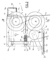
- - Fig. 1 is a diagrammatic front view to a reduced scale of a leather splitting machine provided with a group of sharpening grinding wheels;
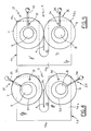
- - Fig. 2 is a side view taken from the left of the sharpening unit according to one embodiment of the invention;
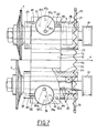
- - Fig. 3 diagrammatically shows the sharpening unit taken along line III-III in Fig. 2;
- - Fig. 4 is a diagrammatic side view of the means for the rapid positioning of the grinding wheels according to the first embodiment, in their opened condition;
- - Fig. 5 is a side view of the means for the rapid positioning of the grinding wheels shown in Fig. 4, in their closed condition;
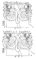
- - Fig. 6 diagrammatically shows a second embodiment of the sharpening unit partly cut away according to a plane transverse to the cutting blade, in which it is clearly shown the means for the rapid positioning of the grinding wheels which are located in a first work condition;
- - Fig. 7 is a front view of the sharpening unit disposed in the same condition as viewed in Fig. 6;
- - Fig. 8 shows the same sharpening unit cut away in the same manner as in Fig. 6, in which the grinding wheels are however disposed in a different work condition.
- Referring to the drawings and in particular to Fig. 1, a splitting machine of a conventional type including a pair of
flywheels 2 and 3 around which aband blade 4 is disposed, has been generally identified byreference numeral 1. A sharpening unit in accordance with the present invention and identified at 5, is provided in the region of the lower portion ofblade 4. - Referring particularly to Figs. 2 and 3, the
sharpening unit 5 is comprised of a pair ofdiamond grinding wheels bevel 4a of thecutting blade 4. - The
grinding wheels respective shafts corresponding pulleys driving belt 12 operated by a motor not shown in the figures and kept tensioned in a manner known per se and conventional by atakeup pulley 13. -
Shafts carriage 14 horizontally movable along guiding rods not shown in the figures and integral with the fixed casing of the splitting machine, from and towards thecutting blade 4. More particularly, themovable carriage 14 is formed with anupright portion 14a from which two substantiallyparallel arms shafts space 15 through which thecutting blade 4 passes. - Still referring to Figs. 2 and 3, 16 denotes a control-adjustment shaft which is supported at 17 by the fixed casing of the
splitting machine 1 and is provided, at one end 16a thereof, with a control-adjustment knob 38 and, at the opposite end, with oneidler element 18. - The
first idler element 18 is operatively connected to asecond idler element 19 fixedly fitted on an adjustingscrew 20. As clearly shown in Fig. 2, the adjustingscrew 20 has oneend 20a screwed in a threadedhole 21 bored in theportion 14a of themovable carriage 14 and the opposite end 20b in abutment against afixed locator element 22 integral with the splitting machine casing. In order to keep the end 20b ofscrew 20 urged against the fixed locatingelement 22 spring means is provided which consists for example of at least a pullingspring 23 one end 23a of which is fastened at 24 to thecarriage 14 and the opposite end 23b is secured at 25 to the fixed casing of the splitting machine. - Idler
elements - The sharpening
unit 5 is further provided, for each grindingwheel wheels respective shafts bearings eccentric bushes housings movable carriage 14. Bushes 30 and 31 are fixedly associated with control levers 34 and 35 which, being acted upon, cause the rotation of the bushes about their own axis so that, as a result, thegrinding wheels - Also associated with the
eccentric bushes diamond grinding wheels limit locators levers limit locators grinding wheels - In the embodiments shown in Figs. 6, 7 and 8 the stop means on the contrary comprises a pair of
stop pins carriage 14, according to an axis substantially at right angles to and sideways offset from one of theshafts grinding wheels stop pin end 68a, 69a designed to abut against a locatinghousing eccentric bush spring 66 or equivalent spring means. Thespring 66 tends to move thegrinding wheels levers housing groove - The
stop pins shanks housings 72a, 73a formed in thecarriage 14. Eachshank adjusting handle corresponding stop pin - Advantageously locking means 76, 77 is associated with each of the
adjusting handles handle movable plug corresponding handle spring - In greater detail, each
plug gripping end respective handle end end handle plug holes handles - A
peg handle limit stops carriage 14 at diametrically opposed positions to prevent the handle from rotating through more than 180°. - Operation of the sharpening unit according to the invention described above mainly as regards structure, is as follows.
- We will start from the condition in which a new blade and/or fresh diamond grinding wheels are mounted on a leather splitting machine.
- Under this situation, the mounting conditions are those viewed in Fig. 4 where the rapid-positioning means is opened. Once the desired mounting has been carried out,
levers grinding wheels - In the embodiment shown in Fig. 5 the work position of the
grinding wheels limit locators wheels housings spring 66 thus preventing theeccentric bushes wheels carriage 14, can therefore be brought into contact with thebevel 4a and sharpen it continuously while the splitting machine is running. - For shifting
carriage 14 it is necessary to act uponknob 38 of the control-adjustment shaft 16. In this way rotations imparted toshaft 16 are transmitted, throughidler elements screw 20 which, by its rotating and abutting against the fixedlocator element 22, causes a horizontal displacement of themovable carriage 14 until the grindingwheels - Advantageously, the device according to the embodiment shown in Figs. 6, 7 and 8 also offers the possibility of modifying the mutual positioning of the grinding
wheels bevel 4a. In fact, in the work conditions seen in Figs. 6 and 7 where themovable plugs holes wheels bevel 4a is sharpened in such a manner that it exhibits a very elongated configuration, its opposite surfaces diverging according to a very narrow angle. When thebevel 4a need to have a shorter configuration, that is a configuration in which its opposite surfaces diverge by a larger angle than in the previous case, the grindingwheels plugs holes plugs holes handles shanks - Due to the displacement of
pins eccentric bushes spring 66 are submitted to an angular rotation the amount of which must be sufficient to maintain the locatinghousings wheels plugs holes 82b, 83b, the mutual positioning of the grindingwheels wheels - Obviously, modifications and variations can be made to the device of the invention without departing from the scope of the inventive idea characterizing it.
Claims (8)
1. A sharpening unit for leather splitting machines characterized in that it comprises a pair of diamond grinding wheels (6, 7) disposed symmetrically relative to the bevel (4a) of the cutting blade (4) and mounted on respective shafts (8, 9) carried by a carriage (14) horizontally movable close to and apart from said cutting blade (4), a control-adjustment shaft (16) provided, at one end thereof, with one idler element (18) operatively connected to a second idler element (19) fixedly fitted on an adjusting screw (20) one end (20a) of which is screwed in a threaded hole (21) bored in the movable carriage (14), whereas the opposite end (20b), thrusted by spring means (23), abuts against a fixed locator element (22) of the splitting machine.
2. A sharpening unit according to claim 1, characterized in that said shafts (8, 9) carrying the grinding wheels (6, 7) are housed in eccentric bushes (30, 31) rotatably supported within respective housings (32, 33) formed in the movable carriage (14) and integrally provided with control levers (34, 35) designed to cause the grinding wheels (6, 7) to rapidly move apart from and close to their working position, through the rotation of the said bushes.
3. A sharpening unit according to claim 1, characterized in that said spring means for urging the adjusting screw (20) against said fixed locator element (22) comprises at least a pulling spring (23) one end (23a) of which is fastened to said movable carriage (14) and the opposite end (23b) is connected to the fixed casing of the splitting machine.
4. A sharpening unit according to claim 2, characterized in that it further comprises a pair of stop pins (68, 69) extending each according to an axis substantially at right angles to and sideways offset from the axis of one of said shafts (8, 9), one end (68a, 69a) of each stop pin being designed to act upon a locating housing (70, 71) formed in the corresponding eccentric bush (30, 31); a pair of threaded shanks (72, 73) each of them operatively engaging in a threaded housing (72a, 73a) formed in the carriage (14) and coaxially supporting said stop pins (68, 69); a pair of adjusting handles (74, 75) fixed each to one of the threaded shanks (72, 73) and operable in rotation to change the axial positioning of the stop pin (68, 69); locking means (76, 77) associated with said adjusting handles (74, 75) to lock them according to predetermined angular positionings which can be individually selected.
5. A sharpening unit according to claim 4, characterized in that said locking means (76, 77) comprises a movable plug (78, 79) for each adjusting handle (74, 75), which plug slidably crosses said handle and is designed to individually and selectively engage at least two holes (82a, 82b, 82c, 83a, 83b, 83c) bored in said carriage (14) in order to fix the angular positioning of said handle (74, 75).
6. A sharpening unit according to claim 4, characterized in that it further comprises at least a pulling spring (66) acting upon said control levers (34, 35) to cause the rotation of the eccentric bushes (30, 31) so as to bring the locating housings (70, 71) in abutment against the stop pins (68, 69).
7. A sharpening unit according to claim 4, characterized in that each of said locating housings (70, 71) consists of a groove (70a, 71a) formed in the corresponding bush (30, 31) at right angles to the axis of rotation of the latter.
8. A sharpening unit according to claim 4, characterized in that each of said adjusting handles (74, 75) is associated with a peg (84, 85) designed to abut against a pair of limit stops (86, 87) fastened to said carriage (14) at diametrically opposed positions relative to the handle itself.
Applications Claiming Priority (4)
| Application Number | Priority Date | Filing Date | Title |
|---|---|---|---|
| IT2119388U | 1988-05-06 | ||
| IT2119388U IT213973Z2 (en) | 1988-05-06 | 1988-05-06 | SHARPENING GROUP FOR LEATHER SPLITTER MACHINES. |
| IT2096389U | 1989-04-26 | ||
| IT2096389U IT216535Z2 (en) | 1989-04-26 | 1989-04-26 | SHARPENING DEVICE FOR BAND SAW BLADES IN BALL SPLITTER MACHINES. |
Publications (2)
| Publication Number | Publication Date |
|---|---|
| EP0341223A2 true EP0341223A2 (en) | 1989-11-08 |
| EP0341223A3 EP0341223A3 (en) | 1991-01-23 |
Family
ID=26327716
Family Applications (1)
| Application Number | Title | Priority Date | Filing Date |
|---|---|---|---|
| EP19890830190 Withdrawn EP0341223A3 (en) | 1988-05-06 | 1989-05-05 | Sharpening unit for leather splitting machines |
Country Status (2)
| Country | Link |
|---|---|
| US (1) | US5027559A (en) |
| EP (1) | EP0341223A3 (en) |
Cited By (1)
| Publication number | Priority date | Publication date | Assignee | Title |
|---|---|---|---|---|
| CN113445716A (en) * | 2021-07-21 | 2021-09-28 | 中信国安建工集团有限公司 | Large-area rigid terrace construction control equipment and operation method |
Families Citing this family (3)
| Publication number | Priority date | Publication date | Assignee | Title |
|---|---|---|---|---|
| KR101765181B1 (en) * | 2015-08-19 | 2017-08-14 | 홍순민 | A potable knife sharpening apparatus |
| SE1551317A1 (en) | 2015-10-13 | 2017-04-14 | Sapa As | Brake tube connector and brake tube connector assembly |
| US20220395271A1 (en) * | 2021-06-15 | 2022-12-15 | Covidien Lp | Staple cartridge with knife sharpener |
Citations (3)
| Publication number | Priority date | Publication date | Assignee | Title |
|---|---|---|---|---|
| FR1235078A (en) * | 1959-09-09 | 1960-07-01 | Slitting machine for leather, skins or the like | |
| FR1511853A (en) * | 1967-02-16 | 1968-02-02 | Ile Dufosset Soc Civ | Semi-automatic band saw sharpener used in garment industries |
| US4713950A (en) * | 1986-05-07 | 1987-12-22 | Camoga S.P.A. | Device adapted to move the sharpening grinding wheels in a leather splitting machine close to and away from a cutting blade |
Family Cites Families (6)
| Publication number | Priority date | Publication date | Assignee | Title |
|---|---|---|---|---|
| US1060287A (en) * | 1907-08-08 | 1913-04-29 | Saranac Machine Co | Machine for grinding or sharpening corrugated-sheet-metal fasteners. |
| US1870817A (en) * | 1927-11-23 | 1932-08-09 | Machines A Affuter Soc Et | Manufacture of knives |
| GB1114415A (en) * | 1964-06-27 | 1968-05-22 | Wilkinson Sword Ltd | Improvements in or relating to grinding and like processes |
| GB1042849A (en) * | 1964-07-17 | 1966-09-14 | Fortuna Werke Spezialmaschinen | Apparatus for width-parallel grinding of the band blade of leather skiving machines |
| GB1311778A (en) * | 1970-04-14 | 1973-03-28 | Rizzi & Co Spa Luigi | Skin splitting machine having a device for sharpening the cutting blade |
| FR2396623A1 (en) * | 1977-07-08 | 1979-02-02 | Lefevre Francois | MACHINE FOR GRINDING OR SHARPENING KNIFE BLADES |
-
1989
- 1989-05-04 US US07/347,460 patent/US5027559A/en not_active Expired - Fee Related
- 1989-05-05 EP EP19890830190 patent/EP0341223A3/en not_active Withdrawn
Patent Citations (3)
| Publication number | Priority date | Publication date | Assignee | Title |
|---|---|---|---|---|
| FR1235078A (en) * | 1959-09-09 | 1960-07-01 | Slitting machine for leather, skins or the like | |
| FR1511853A (en) * | 1967-02-16 | 1968-02-02 | Ile Dufosset Soc Civ | Semi-automatic band saw sharpener used in garment industries |
| US4713950A (en) * | 1986-05-07 | 1987-12-22 | Camoga S.P.A. | Device adapted to move the sharpening grinding wheels in a leather splitting machine close to and away from a cutting blade |
Cited By (1)
| Publication number | Priority date | Publication date | Assignee | Title |
|---|---|---|---|---|
| CN113445716A (en) * | 2021-07-21 | 2021-09-28 | 中信国安建工集团有限公司 | Large-area rigid terrace construction control equipment and operation method |
Also Published As
| Publication number | Publication date |
|---|---|
| US5027559A (en) | 1991-07-02 |
| EP0341223A3 (en) | 1991-01-23 |
Similar Documents
| Publication | Publication Date | Title |
|---|---|---|
| AU739804B2 (en) | Sharpener assembly for a food slicer and related method | |
| US3183948A (en) | Saw chain | |
| US3147644A (en) | Sharpening means for chain saws | |
| US3952616A (en) | Adjustable grinding apparatus | |
| US3779103A (en) | Chipper chain grinder | |
| US4104793A (en) | Saw chain sharpener | |
| US4732056A (en) | Saw chain grinding machine | |
| GB2050939A (en) | Panel scoring saw | |
| US5027559A (en) | Sharpening unit for leather splitting machines | |
| US4031672A (en) | Sharpen twist drills or the like | |
| US2410828A (en) | Chain saw sharpener | |
| CA1080976A (en) | Sharpener mounting structure and knife guard for circular knife type of cloth cutting machine | |
| US5480345A (en) | Knife sharpener | |
| US5038639A (en) | Saw blade top and face grinder | |
| US3020783A (en) | Chain saw sharpener | |
| US4823649A (en) | Automatic dual side grinder | |
| US4016680A (en) | Sharpener for twist drills including grinding wheel dressing means | |
| US3930342A (en) | Sharpener for twist drills | |
| US5101690A (en) | Saw blade top and face grinder | |
| US5033333A (en) | Saw chain grinding machine | |
| US4019407A (en) | Saw chain grinder fixture | |
| US3993115A (en) | Tire truing machine | |
| JPH0541384B2 (en) | ||
| US3271906A (en) | Blade sharpener | |
| US3066456A (en) | Work moving machine |
Legal Events
| Date | Code | Title | Description |
|---|---|---|---|
| PUAI | Public reference made under article 153(3) epc to a published international application that has entered the european phase |
Free format text: ORIGINAL CODE: 0009012 |
|
| AK | Designated contracting states |
Kind code of ref document: A2 Designated state(s): DE GB |
|
| PUAL | Search report despatched |
Free format text: ORIGINAL CODE: 0009013 |
|
| AK | Designated contracting states |
Kind code of ref document: A3 Designated state(s): DE GB |
|
| STAA | Information on the status of an ep patent application or granted ep patent |
Free format text: STATUS: THE APPLICATION IS DEEMED TO BE WITHDRAWN |
|
| 18D | Application deemed to be withdrawn |
Effective date: 19910724 |