EP0341086A2 - Bildgenerator vom Typ unabhängiger Zellen - Google Patents
Bildgenerator vom Typ unabhängiger Zellen Download PDFInfo
- Publication number
- EP0341086A2 EP0341086A2 EP89304593A EP89304593A EP0341086A2 EP 0341086 A2 EP0341086 A2 EP 0341086A2 EP 89304593 A EP89304593 A EP 89304593A EP 89304593 A EP89304593 A EP 89304593A EP 0341086 A2 EP0341086 A2 EP 0341086A2
- Authority
- EP
- European Patent Office
- Prior art keywords
- cell
- data
- raster scan
- line
- storage means
- Prior art date
- Legal status (The legal status is an assumption and is not a legal conclusion. Google has not performed a legal analysis and makes no representation as to the accuracy of the status listed.)
- Withdrawn
Links
Images


Classifications
-
- G—PHYSICS
- G09—EDUCATION; CRYPTOGRAPHY; DISPLAY; ADVERTISING; SEALS
- G09G—ARRANGEMENTS OR CIRCUITS FOR CONTROL OF INDICATING DEVICES USING STATIC MEANS TO PRESENT VARIABLE INFORMATION
- G09G5/00—Control arrangements or circuits for visual indicators common to cathode-ray tube indicators and other visual indicators
- G09G5/42—Control arrangements or circuits for visual indicators common to cathode-ray tube indicators and other visual indicators characterised by the display of patterns using a display memory without fixed position correspondence between the display memory contents and the display position on the screen
-
- G—PHYSICS
- G06—COMPUTING OR CALCULATING; COUNTING
- G06K—GRAPHICAL DATA READING; PRESENTATION OF DATA; RECORD CARRIERS; HANDLING RECORD CARRIERS
- G06K15/00—Arrangements for producing a permanent visual presentation of the output data, e.g. computer output printers
-
- G—PHYSICS
- G06—COMPUTING OR CALCULATING; COUNTING
- G06K—GRAPHICAL DATA READING; PRESENTATION OF DATA; RECORD CARRIERS; HANDLING RECORD CARRIERS
- G06K15/00—Arrangements for producing a permanent visual presentation of the output data, e.g. computer output printers
- G06K15/02—Arrangements for producing a permanent visual presentation of the output data, e.g. computer output printers using printers
-
- G—PHYSICS
- G06—COMPUTING OR CALCULATING; COUNTING
- G06K—GRAPHICAL DATA READING; PRESENTATION OF DATA; RECORD CARRIERS; HANDLING RECORD CARRIERS
- G06K2215/00—Arrangements for producing a permanent visual presentation of the output data
- G06K2215/0002—Handling the output data
- G06K2215/0077—Raster outputting to the print element(s)
Definitions
- This invention relates to a printer controller for organizing data from a host computer to print the data on a print engine, preferably of the type using charged transfer imaging, and more particularly to an image generator used in the printer controller.
- Printer controllers which are designed to receive data from the host computer are commonly limited to locating cells relative to one another in a fixed manner dictated by each cell being located by reference to the cells around it.
- the cells can not be overlapped or start at the same location.
- Such limitations restrict the kind of text information that can be handled by the controller and printed as hard copy by a print engine.
- Such techniques as proportional spacing, kerning, superscripts, subscripts, and mixed point sizes of text may not be possible.
- the limitations on the locations of the cells may also restrict the locations of bit maps and text information. As a result the overlay of a bit map representing a business form with text information may not be possible.
- the present invention provides methods and apparatus for handling cell data essentially independently of other cell data on a page so that the resulting printed representation of the page will have cells positioned independently of one another making it possible, for instance, to superimpose such combinations as forms and text in the page.
- the invention provides apparatus for organising digital data received from a source such as a host computer into a raster scan order, the apparatus comprising: cell data means for storing cell data representing the first line of the raster scan in which the cell occurs, the location of the first bit of the cell in the raster scan line, the number of raster scan lines in the cell, and the address of the data defining the first line of the cell for use in adding the cell data to the raster scan; cell list means for storing cell data representing sequential scan lines of the data making up the cell at said address; new cell storage means for receiving and storing individual cell data sequentially from the cell data means in the order in which the cell data is to be added to the raster scan; current cell storage means for receiving and temporarily storing said cell data representing the first bit location, the number of raster scan lines in the cell, and the address of the data in the cell list for comparison with the corresponding cell data in said new cell storage means and including means for adjusting the cell data prior to comparison to represent a decremented
- the invention provides a method of organising digital data received from a source such as a host computer into raster scan order, the method comprising the steps: storing cell data for cells to be added to the raster scan, the data for each cell representing the first line of the raster scan in which the new cell occurs, the location of the first bit of the cell in the raster scan line, the number of raster scan lines in the cell, and the address of the data defining the first line of the cell for use in adding the cell data to the raster scan; storing cell lists representing sequential scan lines making up the cells at said addresses; providing a new cell storage means and receiving and storing individual cell data sequentially in the order in which the cell data is to be added to the raster scan in this storage means; providing current cell storage means and receiving and temporarily storing said cell data representing the first bit location, the number of raster scan lines in the cell, and the address of the data in the cell list and comparing this data with the corresponding cell data in said new cell storage means and adjusting the
- the invention provides a method of arranging data representing graphics in cells positioned independently on a page into raster scan order for transmission to a printer of the type which converts raster scan ordered bits into arrangements needed to print the graphics at the required positions on the page, the method comprising the steps: storing data representing the cells, the data including the number of the raster scan on which the cell starts, the number of scan lines occupied by the cell, the bit position on the scan line where the first of the cell bits resides, and the address of the data representing the first of the lines of the cell; fetching the cell data in order of scan line and bit position on that scan line, and storing that data temporarily at a new cell storage means; passing the data through a sequential storage means, storing the bit position and address of this data, comparing the bit position with that of a bit counter and, when they match, using the address to fetch the data for the cell line and combining this data with the scan line at the bit location and entering this data into a current cell storage means; manipulating the data in the current
- the invention provides apparatus for organising digital data received from a source such as a host computer into raster scan order, the apparatus comprising: a cell data memory for storing cell data representing the first line of the raster scan in which the cell occurs, the location of the first bit of the cell in the raster scan line, the number of raster scan lines in the cell, and the address of the data defining the first line of the cell for use in adding the cell data to the raster scan; a cell list memory for storing cell data representing sequential scan lines of the data making up the cell at said address; a new cell register for receiving and storing individual cell data sequentially from the cell data memory in the order in which the cell data is to be added to the raster scan; a current cell register for receiving and temporarily storing said cell data representing the first bit location, the number of raster scan lines in the cell, and the address of the data in the cell list for comparison with the corresponding cell data in said new cell storage memory and including means for adjusting the cell data prior to comparison to represent a source such as
- the invention provides a method of arranging independent cell data for at least one cell on a page in raster scan order, the method comprising the steps: storing first cell data in a cell list with each entry in the list representing one line of a cell; storing second cell data defining the raster scan line which will receive the first of said entries, the bit position on the raster scan lines where the cell starts, the number of lines contained in the cell, and the address of the first of said entries for the first cell data; fetching the second cell data in order of said first raster scan line and smallest bit position; counting the raster scan lines; comparing each of the fetched second cell data with the raster scan line number and if they match, comparing the fetched second cell data with an earlier fetched second cell data which has been adjusted to contain a new address for the next entry of first cell data for that cell and storing the cell data having the earlier first bit in sequential storage for subsequent comparison as said earlier fetched second cell data; and, storing the second cell data
- Fig. 1 illustrates a printer designated generally by the numeral 20 connected to a computer 22 to receive data from the computer for converting to a hard copy in a print engine 24 forming part of the printer.
- a printer controller 26 controls the operations of a paper feeder 28 providing paper for the print engine 24, and of a paper stacker 30 which receives the finished printed page.
- Data from the computer represents images within individual cells which can be multiples of 32 bits (i.e. for the purposes of this description, two words) wide and have a height of from 1 to 256 lines.
- the position of an individual cell is represented with reference to the page by identifying the left top corner of the cell in terms of its bit position on a particular line and the number of the line on which it occurs. This will be described in more detail with reference to an example which is identified in Fig. 4.
- the printer controller is better seen in Fig. 2 where it will be seen that the printer controller 26 interfaces with the computer 22 via a communications interface 32. This is facilitated by a control logic 34 which also controls an image generator memory 36 and image generator 38. Data leaves the printer controller in bytes of 8 bits which are fed to the print engine as indicated in Fig. 2 and shown in Fig. 1.
- cells to be printed are stored in the image generator memory in terms of their specification and position on the printed page using any suitable sorting procedure to position the data in memory. (Alternative memory arrangements can of course be used).
- bit maps for individual cells to represent a selected font or other graphics data is stored in two parts, a cell list which defines the cell, and cell data, the address of which is included in the cell specification so that the data can be withdrawn to be fed to the print engine by the control logic and image generator.
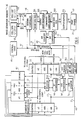
- Fig. 3 to describe in general terms the image generator 38.
- the operation of the generator and further explanation of it will be included in a description of the exemplary operation of the printer.
- the image generator is essentially in two parts, namely a cell sequencer 40 shown generally to the left of Fig. 3, and an image assembler 42 shown generally to the right of Fig. 3.
- the sequencer 40 is used to fetch cell data from a cell list 44 which is stored sequentially in the memory.
- This memory forms part of the image generator memory 36 and a processor 46 forms part of the control logic 34 (Fig. 2).
- a memory controller 48 is used for this purpose triggered by a list pointer 50 operated as will be described later.
- the cells are fetched from the cell list and positioned in a new cell register 52 in the order in which they are to be placed on the page of text.
- the cell in the new cell register 52 is compared with a cell in a current cell register 56 and, depending upon which cell is to be printed first, that cell will, as a result of comparison in line comparator 58 and bit comparator 60, be selected for entry into a cell FIFO 62.
- the procedure is to cycle the cells through the FIFO and current cell register while increasing the line count and decreasing the number of lines left in the cell (the 'cell height') until that cell is exhausted.
- the line count continues and the cycling continues bringing in new cells via the new cell register until all of the cells have been accommodated and the page is completed.
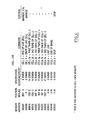
- Fig. 4 shows an exemplary cell list for use in illustrating the operation of the image generator, and initially of the cell sequencer 40 (Fig. 3).
- the cells appear as 8 memory addresses (the addresses being hexadecimal).
- the memory is actually four 8-bit bytes wide so that for each cell two rows of the memory are used.
- the first cell listed is an end of line (EOL) cell which is identified as the last dot position (2047) on a line.
- the height of the cell is zero and its address in the cell data memory is 001000.
- the next cell is cell 1 which represents the start of a line (SOL) and that has a bit position of 0 with a line position of 1.
- SOL start of a line
- the address is also at 001000 in the cell data memory because these represent similar output. To facilitate this, there must be sufficient zero data at 00100 so that the data fetched for cells 0 and 1 does not interfere with the image.
- Cell 0 is located at the end of the raster scan line (dot position 2047 in this example) and has the EOL bit set. Cell 0 defines the length of the raster scan line.
- Cell 1 is required because only image data and the bit position for this data are sent to the image assembler 42. If only cell 0 were in 5462, the image assembler 42 would not output a raster scan line for each cycle of cell 0 through the cell FIFO. It would overlay each occurrence of cell 0.
- Cell 0 and cell 1 have the marker bit set. This prevents the control logic from discarding cells 0 and 1 when their height is exhausted as will be explained. The height value for the cell therefore has no meaning and cell 0 and cell 1 never end until the scanning of the page is completed as will be explained.
- cell 2 is in three parts.
- Cells can be multiples of 32 bits and this cell is represented by three 32 bit parts, namely 2a, 2b and 2c. These are best considered as dependent cells but it will be recognized that the three together represent a bit map for a character or graphic representation within the cell 2 as a whole.
- Cell 3 is also made up of three parts and is positioned so that it overlaps with cell 2 as seen in Fig. 4.
- Fig. 4 represents the position of the cell on a page which is 2048 bits wide and 40 rows high.
- Cell 2 commences at bit 1023 on row 12 and is 14 rows high.
- cell 3 commences at bit 959 on row 18 and is 17 rows high.
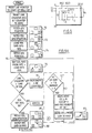
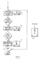
- Figs. 3 and 6 initially the cell list is loaded at 44 in the image generator memory and the line counter 54 and bit counter 68 shown in Fig. 3 are set to zero.
- the first cell is then fetched from the cell list 44 in terms of its position which is represented in the new cell register by bit and line.
- schematic drawings of arrangements such as that indicated by numeral 70 are included in Fig. 6.
- 70 represents the three major parts of the cell sequencer 40.
- To the bottom right is the new cell register in two parts, i.e. the position at the bottom and the specification at the top; the center and top represents the FIFO contents 62, and the bottom left represents the current cell register 56 and its contents.
- the next step after 74 is to get the EOL data from the FIFO and load it into the CCR as shown at 76.
- the line counter is incremented at 78 and the procedure moves into a section designated as "A”.
- the height of the cell in the CCR i.e. cell 0
- the cell height is not 1 and the marker bit is set so the cell in the CCR is incremented by 4 addresses and the height is decremented by 1. However, since the height in this case is 0, the decrement will have no effect.
- the increase in the address is used at the image data address register 64 as will be described. For the moment the order of operations around the sequencer will be described and then the effect of the address changes on the image data address register 64 and on the image assembler 42 will be described separately.
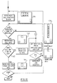
- a subsequent part of the diagram shown in Fig. 6 is to process the cells 2 and 3 shown in Fig. 5 commencing with an operation 90 to fetch the next cell position to the NCR. This results in the arrangement shown at 92.
- a test is then conducted to determine whether the line counter is equal to the line number of cell 2. The answer is "no" because cell 2 occurs at line 12. Consequently lines up to line 11 will have to be passed before there is an answer of "yes” to this test.
- a loop is provided to enable the lines to cycle commencing with the procedure denoted "A" where the end of line cell is moved from the CCR to the FIFO resulting in arrangement 94.
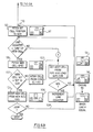
- Fig. 8 is again a repetition of the lower part of Fig. 6 and illustrates the next steps in the procedure following those in Fig. 7.
- the next cell position is fetched from memory to create the arrangement 120.
- this cell starts on line 18 at a bit position 959. Consequently, it will have no effect on lines 12 through 17 so that when the line position is compared, there will be no activity with cell 3a until line 18 is reached.
- Fig. 8 where the procedure is similar to that shown in Fig. 6.
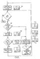
- Fig. 9. This will be seen to be similar to Fig. 7 and uses the same loop. Initially the next cell position, cell 3b, is fetched to the NCR and then the cell spec. is fetched resulting in the arrangement shown in 130. After this, and because cell 3b has a bit position of 991 (see Fig. 4) this cell must be entered ahead of cell 2a which has a position of 1023. This results in the arrangement shown at 132. The looping then takes place to bring in cell 3b which also will be entered ahead of 2a and then, because 3c has the same bit position as 2a it will also be entered ahead. The result after this cycling is completed is the arrangement shown at 134 drawn to the right of Fig. 9.
- the procedure "A" includes a discard when the height of a cell in the CCR is equal to 1 and the marker bit is 0. Consequently, in the looping shown in Fig. 10, when the procedure "A" is met by a cell having a height 1 and a marker bit 0, this cell is not moved to the FIFO but simply ignored. The next cell entering the CCR writes over the cell which has been discarded and is then tested itself. Initially all three cells 2a, 2b, and 2c will be discarded in this way at line 26 resulting in the loop continuing only with cells 3a, 3b, and 3c until line 35 is reached when these cells will also be discarded.
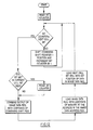
- the position of cell 5 is fetched to the NCR creating arrangement 146.
- the STOP control bit is checked next. In this case the bit is not set, meaning there are more cells to come. Because cell 5 is on line 40 and the cell counter is at 39, the test at 148 will result in "no" bringing into play the loop containing "A" which creates the arrangement 150, and 152 before looping back. The loop will continue until the arrangement shown at 154 is created at which point the line counter moves to 40 so that 148 will give a "yes” answer.
- the new cell spec. is then fetched to create the arrangement 156 and then data for cell 5 is moved into the FIFO with the resultant arrangement 158.
- the cell position of cell 6 is fetched and loaded into the NCR.
- the STOP control bit is set for cell 6. This is detected by the control logic during the next loop back which stops output of the image.
- the address carried by that data is passed to the image data address register 64.
- This is an address in the cell data memory of 32 bits of information to be added to the raster scan at a bit position designated by the bit information from the same cell.
- the bit information is loaded from the CCR into the next cell bit register 162.
- the bit position held in the next cell bit register is for the image data held in the image data register, this data having been fetched from the image generator memory at the address held in the image data address register 64.
- This bit information is passed to a comparator 162 which compares that bit position with the bit count of 68. So long as the bit position and the bit count are not equal, the control logic causes the data in the combining shift register to be shifted into the output shift register. When the bit position and the bit count are equal, the control logic causes the data from the image data register 164 to be OR'd with the data in the combining shift register 166. Serial data from this register represents a combination of the raster scan and the image data and is passed serially to a output shift register which has an 8-bit parallel output. Each 8 bits shifted into the output shift register is loaded as one byte into a FIFO 168 and then to an output buffer 170 from which the data passes in 8-bit bytes to the print engine 24.
- the operation of the image assembler 42 is illustrated in a flow chart shown in Fig. 12.
- the image assembler will be described with reference to Figs. 3 and 12.
- the bit counter 68 is reset and a test conducted to determine whether the bit counter is equal to the next cell bit in the register 162. If the answer is "no", the combining shift register is shifted one position by the control logic and the bit counter 68 is incremented by 1, also by the control logic. The test is conducted again to determine whether the bit counter is equal to the next cell bit and this loop continues until the answer is "yes".
- the address in the image data register 64 is used by the control logic to fetch corresponding image data from the address in the cell data memory to the image data register 164.
- the next cell bit register 162 is loaded with the bit position of the same data and the data will remain in the image data register 164 until the bit comparator 162 instructs the control logic that the bit counter has reached the next cell bit contained in the register 162. This will cause the flow chart to loop and the procedure to be completed.
- Data leaving the combining shift register 166 serially is entered serially into an output shift register from which it is moved in 8-bit bytes to an image data FIFO 168 and subsequently to an output buffer 170 before being shifted to the print engine 24.
- the circuitry described in the above description can of course be varied within the scope of the invention.
- the cell list is stored in sequential memory locations in the example given but this restriction can be removed by defining a JUMP command.
- This command is used in a cell list to continue the cell list at an arbitrary address and the JUMP command is loaded into the new cell register 52 in the same way as the cell specification.
- a control bit is tested by the control logic and if the contents of the NCR is a JUMP, then the address contained in the JUMP command is loaded into the list pointer 50 and a new cell specification is fetched.
- control bits in the cell specification can be defined to specify how many 32 bit strips are required for the logical cell. These control bits would cause the current cell register to register to increment the image data address by an appropriate amount at the next image data for the strip. As an example, a 96 bit wide character requires 3 x 32 bit strips and the image data address for the 3 cells in the cell list would be incremented by 12 rather than the normal 4 in the example given.
- the widths of the image data register and the combining shift register in the example given are the same as the image generator memory.
- the image data register and combining shift register can be wider by multiples of the image generator memory width.
- the image data register would be loaded by multiple accesses to the image generator memory.
Landscapes
- Engineering & Computer Science (AREA)
- Physics & Mathematics (AREA)
- General Physics & Mathematics (AREA)
- Theoretical Computer Science (AREA)
- General Engineering & Computer Science (AREA)
- Computer Hardware Design (AREA)
- Image Processing (AREA)
- Image Input (AREA)
Applications Claiming Priority (2)
| Application Number | Priority Date | Filing Date | Title |
|---|---|---|---|
| US07/190,427 US5016190A (en) | 1988-05-05 | 1988-05-05 | Development of raster scan images from independent cells of imaged data |
| US190427 | 1988-05-05 |
Publications (2)
| Publication Number | Publication Date |
|---|---|
| EP0341086A2 true EP0341086A2 (de) | 1989-11-08 |
| EP0341086A3 EP0341086A3 (de) | 1991-12-11 |
Family
ID=22701312
Family Applications (1)
| Application Number | Title | Priority Date | Filing Date |
|---|---|---|---|
| EP19890304593 Withdrawn EP0341086A3 (de) | 1988-05-05 | 1989-05-05 | Bildgenerator vom Typ unabhängiger Zellen |
Country Status (2)
| Country | Link |
|---|---|
| US (1) | US5016190A (de) |
| EP (1) | EP0341086A3 (de) |
Families Citing this family (5)
| Publication number | Priority date | Publication date | Assignee | Title |
|---|---|---|---|---|
| US5619622A (en) * | 1994-12-16 | 1997-04-08 | Xerox Corporation | Raster output interface for a printbar |
| US5579453A (en) * | 1994-12-16 | 1996-11-26 | Xerox Corporation | Smart direct memory access controller |
| US5971523A (en) * | 1997-06-26 | 1999-10-26 | Xerox Corporation | Liquid ink printer having multiple processors for fast color imaging |
| US5898393A (en) * | 1997-06-26 | 1999-04-27 | Xerox Corporation | Data translating memory system |
| US20040095596A1 (en) * | 2002-11-14 | 2004-05-20 | International Business Machines Corporation | Apparatus, method and program product for controlling printing |
Family Cites Families (13)
| Publication number | Priority date | Publication date | Assignee | Title |
|---|---|---|---|---|
| US4028680A (en) * | 1971-09-29 | 1977-06-07 | Ing. C. Olivetti & C., S.P.A. | System for automatically processing and printing the contents and the format of a text |
| US4007442A (en) * | 1974-11-11 | 1977-02-08 | International Business Machines Corporation | Intermixed line heights and blank line formation in a buffered printer |
| US3952852A (en) * | 1975-01-22 | 1976-04-27 | International Business Machines Corporation | Column format control system |
| US4042958A (en) * | 1975-09-10 | 1977-08-16 | Idr, Inc. | Row grabbing system |
| US4212553A (en) * | 1978-03-06 | 1980-07-15 | International Business Machines Corporation | Tabulation control system having two electronic tab racks |
| US4207011A (en) * | 1978-03-06 | 1980-06-10 | International Business Machines Corporation | Line spacing and column format control system |
| US4205922A (en) * | 1978-03-06 | 1980-06-03 | International Business Machines Corporation | Font and column format control system |
| US4591846A (en) * | 1982-09-28 | 1986-05-27 | Burroughs Corp. | Real time cell specification processor |
| EP0121015B1 (de) * | 1983-03-31 | 1990-03-07 | International Business Machines Corporation | Abbildungsraumverwaltung und Wiedergabe in einem bestimmten Teil des Bildschirms eines virtuellen Mehrfunktionsterminals |
| US4653020A (en) * | 1983-10-17 | 1987-03-24 | International Business Machines Corporation | Display of multiple data windows in a multi-tasking system |
| US4648045A (en) * | 1984-05-23 | 1987-03-03 | The Board Of Trustees Of The Leland Standford Jr. University | High speed memory and processor system for raster display |
| NL8402998A (nl) * | 1984-10-02 | 1986-05-01 | Oce Nederland Bv | Decoder. |
| US4841453A (en) * | 1986-11-10 | 1989-06-20 | Ibm Corporation | Multidirectional scan and print capability |
-
1988
- 1988-05-05 US US07/190,427 patent/US5016190A/en not_active Expired - Fee Related
-
1989
- 1989-05-05 EP EP19890304593 patent/EP0341086A3/de not_active Withdrawn
Also Published As
| Publication number | Publication date |
|---|---|
| US5016190A (en) | 1991-05-14 |
| EP0341086A3 (de) | 1991-12-11 |
Similar Documents
| Publication | Publication Date | Title |
|---|---|---|
| US4593407A (en) | Pattern processing system | |
| US4300206A (en) | Flexible text and image generator for a raster printer | |
| US4079458A (en) | High resolution character generator | |
| EP0185294B1 (de) | Anzeigegerät | |
| CA1235535A (en) | Method of providing raster information for a graphics display | |
| US4905166A (en) | Method of generating line parts | |
| EP0030279B1 (de) | System zum Drucken eines Unterschriftbildes mit einem Matrixdrucker | |
| EP0153877A2 (de) | Schaltung zur Zwischenspeicherung von Bilddaten | |
| US4646259A (en) | Strip map memory controller | |
| EP0267418B1 (de) | Mehrrichtungs-Abtast- und -Druckfähigkeit | |
| CA1122717A (en) | Data bit assembler | |
| US5146547A (en) | Printer buffer and rasterization arrangement | |
| EP0100853B1 (de) | Zeichengenerator für Rasterdrucker | |
| US4860219A (en) | High speed printer | |
| US5043918A (en) | Multiple bus image controller structure for color page printers | |
| US5299310A (en) | Flexible frame buffer for raster output devices | |
| US6023343A (en) | Method and apparatus for temporary storage on disk of collated print data | |
| EP0241091A1 (de) | Gerät und Verfahren zum Drucken von Information | |
| EP0341086A2 (de) | Bildgenerator vom Typ unabhängiger Zellen | |
| GB2174277A (en) | Method and system for displaying multiple images on a display screen | |
| US5371518A (en) | Video timing and display ID generator | |
| EP0090802B1 (de) | Seitenmodifikationsverfahren in einem drucker-subsystem der mit teilseitenpuffern aufsetzenden art | |
| US6628289B1 (en) | Rendering apparatus and method, and storage medium | |
| WO1983003487A1 (en) | Page printing system | |
| CA1249627A (en) | Printer input interface |
Legal Events
| Date | Code | Title | Description |
|---|---|---|---|
| PUAI | Public reference made under article 153(3) epc to a published international application that has entered the european phase |
Free format text: ORIGINAL CODE: 0009012 |
|
| AK | Designated contracting states |
Kind code of ref document: A2 Designated state(s): DE FR GB IT |
|
| PUAL | Search report despatched |
Free format text: ORIGINAL CODE: 0009013 |
|
| AK | Designated contracting states |
Kind code of ref document: A3 Designated state(s): DE FR GB IT |
|
| STAA | Information on the status of an ep patent application or granted ep patent |
Free format text: STATUS: THE APPLICATION IS DEEMED TO BE WITHDRAWN |
|
| 18D | Application deemed to be withdrawn |
Effective date: 19911202 |