EP0341032A2 - Method and apparatus for laying a filament - Google Patents
Method and apparatus for laying a filament Download PDFInfo
- Publication number
- EP0341032A2 EP0341032A2 EP89304423A EP89304423A EP0341032A2 EP 0341032 A2 EP0341032 A2 EP 0341032A2 EP 89304423 A EP89304423 A EP 89304423A EP 89304423 A EP89304423 A EP 89304423A EP 0341032 A2 EP0341032 A2 EP 0341032A2
- Authority
- EP
- European Patent Office
- Prior art keywords
- filament
- substrate
- sheet
- onto
- elongate
- Prior art date
- Legal status (The legal status is an assumption and is not a legal conclusion. Google has not performed a legal analysis and makes no representation as to the accuracy of the status listed.)
- Withdrawn
Links
Images

Classifications
-
- D—TEXTILES; PAPER
- D04—BRAIDING; LACE-MAKING; KNITTING; TRIMMINGS; NON-WOVEN FABRICS
- D04H—MAKING TEXTILE FABRICS, e.g. FROM FIBRES OR FILAMENTARY MATERIAL; FABRICS MADE BY SUCH PROCESSES OR APPARATUS, e.g. FELTS, NON-WOVEN FABRICS; COTTON-WOOL; WADDING ; NON-WOVEN FABRICS FROM STAPLE FIBRES, FILAMENTS OR YARNS, BONDED WITH AT LEAST ONE WEB-LIKE MATERIAL DURING THEIR CONSOLIDATION
- D04H3/00—Non-woven fabrics formed wholly or mainly of yarns or like filamentary material of substantial length
- D04H3/02—Non-woven fabrics formed wholly or mainly of yarns or like filamentary material of substantial length characterised by the method of forming fleeces or layers, e.g. reorientation of yarns or filaments
- D04H3/04—Non-woven fabrics formed wholly or mainly of yarns or like filamentary material of substantial length characterised by the method of forming fleeces or layers, e.g. reorientation of yarns or filaments in rectilinear paths, e.g. crossing at right angles
- D04H3/045—Non-woven fabrics formed wholly or mainly of yarns or like filamentary material of substantial length characterised by the method of forming fleeces or layers, e.g. reorientation of yarns or filaments in rectilinear paths, e.g. crossing at right angles for net manufacturing
-
- Y—GENERAL TAGGING OF NEW TECHNOLOGICAL DEVELOPMENTS; GENERAL TAGGING OF CROSS-SECTIONAL TECHNOLOGIES SPANNING OVER SEVERAL SECTIONS OF THE IPC; TECHNICAL SUBJECTS COVERED BY FORMER USPC CROSS-REFERENCE ART COLLECTIONS [XRACs] AND DIGESTS
- Y10—TECHNICAL SUBJECTS COVERED BY FORMER USPC
- Y10T—TECHNICAL SUBJECTS COVERED BY FORMER US CLASSIFICATION
- Y10T156/00—Adhesive bonding and miscellaneous chemical manufacture
- Y10T156/17—Surface bonding means and/or assemblymeans with work feeding or handling means
- Y10T156/1702—For plural parts or plural areas of single part
- Y10T156/1712—Indefinite or running length work
- Y10T156/1722—Means applying fluent adhesive or adhesive activator material between layers
Definitions
- the present invention relates to a method and apparatus for laying a filament, and in particular, but not exclusively, to a method and apparatus for laying a weft yarn onto a substrate on which the weft yarn is to be secured.
- plastics sheeting One application where it is necessary to lay a weft yarn onto a substrate occurs in the manufacture of reinforced plastics sheeting, the plastics sheeting being reinforced with a first set of fibres arranged perpendicularly to a second set of fibres.
- the known method for producing such a reinforced sheet is to first apply the plastics to a paper backing sheet withdrawn from a storage roll, the plastics being applied in liquid form, usually in the form of a solution. Reinforcing weft fibres are then laid across the width of the backing paper onto the liquid plastics, and are embedded therein. This is conventionally done by means of a travelling head which traverses across the width of the backing sheet and which lays down a weft yarn which sinks into, and becomes embedded in, the liquid plastics. By traversing backwards and forwards, a series of weft yarns is produced.
- the problem with all such travelling heads is that the resultant yarn laid down onto the plastics is not particularly accurate, in that the spacings between adjacent weft yarns can vary by several millimetres, perhaps as much as 5 mm in either direction from the correct location. This does not cause too much of a problem when the spacing of adjacent weft yarns is intended to be relatively large, but if the spacing of adjacent weft yarns becomes smaller, then the error involved in using the above apparatus becomes significant.
- an apparatus for laying a filament onto a substrate comprises compressed gas projection means for projecting the filament across the substrate, an elongate hollow chamber spaced from the substrate into which the filament is projected, the chamber having a closeable elongate aperture along its length, means for opening and closing the elongate aperture, clamping means situated adjacent each end of the elongate chamber for clamping the projected filament when in the closed chamber, and displacement means for displacing the clamped filament through the opened elongate aperture of the chamber onto the substrate.
- Such an apparatus allows rapid laying of the filament by virtue of the compressed gas projection means, and the filament is laid accurately by virtue of the fact that it is clamped in position and then displaced into engagement with the substrate.
- the apparatus further comprises severing means for severing the filament to be laid down from the supply of filament.
- the clamping means and/or the displacement means are adapted to apply a tension to the clamped filament before application onto the substrate.
- the clamping means and the displacement means may comprise a movable clamping head which is movable into abutment with a clamping base, to clamp the filament therebetween.
- the clamping base is movable, against the force of a resiliently deformable member, such that the clamped filament may be moved towards the substrate through the opened aperture in the elongate hollow chamber.
- the or each apparatus may be movable, for example pivotally mounted, which enables filaments to be applied to the substrate at different angles.
- the aperture in the elongate hollow chamber may be opened and closked by means of a movable, preferably flexible, flat.
- the flap may be resiliently deformable and may be integrally formed with the elongate hollow chamber.
- a method of laying a filament onto a substrate comprises projecting the filament through an elongate hollow chamber spaced apart from the substrate, clamping the filament above the substrate when inside the chamber and displacing the clamped filament through an opened elongate, closeable aperture in the hollow member onto the substrate.
- the filament is projected by means of compressed gas.
- a tension is applied to the clamped filament before it is displaced onto the substrate.
- a method of applying one or more filaments on to a moving sheet comprises passing the moving sheet over a roller or other direction-changing device and laying the or each filament onto the sheet at, or in the vicinity of, the direction-changing device, the angle of inclination of the or each filament to be layed onto the sheet with respect to the portion of the sheet upstream of the direction-changing device being less than the angle through which the direction of the sheet is changed.
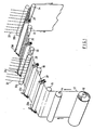
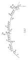
- FIG. 1 there is illustrated an apparatus for forming a plastics sheet reinforced with filaments extending along and across the sheet.
- the apparatus comprises a dispensing roller 10 from which a continuous sheet of backing paper 12 is dispensed.
- One surface of the backing paper 12 is coated with a liquid plastics coating, in the form of plastics dissolved in a solvent, by means of an application roller 14.
- the coated backing paper then passes over a first direction-changing roller 16 and over four further direction-changing rollers 18, 20, 22, 24.
- a device 26a to 26d illustrated schematically in Fig. 1, for laying down a filament 28 across the coated backing paper onto the liquid plastics coating, the filament extending in a direction substantially perpendicular to the direction of motion of the coated backing paper 12.
- transverse filament laying rollers 30a, 30b are situated warp filament laying rollers 30a, 30b respectively.
- Each of the rollers is adapted to guide a plurality of longitudinal warp filaments 32 to lie in a direction substantially parallel to the direction of motion of the coated backing paper 12.
- the rollers are arranged to divert the direction of motion of the coated backing paper 12.
- the middle roller 20 and the final roller 24 are adapted to divert the plane of the paper through angles x1 and x2 respectively.
- the longitudinal or warp threads 32 define angles y1 and y2, such that y1 ⁇ x1 and y2 ⁇ x2. In this way, as the warp threads are laid onto the coated substrate, they are pressed firmly into the substrate at the rollers 20, 24 respectively.
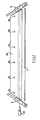
- the device for applying the transverse filaments is shown in more detail in Figs. 2 to 6.
- the device comprises a metal base 34 comprising a planar upper section 36 and a planar lower section 38 extending perpendicularly to the upper section 36.
- An elongate flexible plenum member 40 made out of, for example, Neoprene (Trade Mark) projects beyond the end of the planar member 38, and is secured thereto by means of an angled bracket 42 which is secured to the planar member 38 by means of a bolt 44.
- One end of the bracket 42 fits into an elongate groove in the flexible elongate plenum member 40.
- the plenum member 40 comprises an upper, solid portion 48 from which a relatively rigid flap 50 depends downwardly.
- the opposite side of the plenum member is provided with a thinner flap 52, defining an elongate plenum chamber 54, which is bulbous in cross-section, therebetween.
- the plenum member 40 naturally assumes the shape illustrated in Fig. 4, but can be constrained to assume the shape illustrated in Fig. 3 by means of a flap moving plate 56 which engages in an elongate groove 58 defined by an elongate rib 60 on the outer face of the flap 52.
- the flap actuating member 56 is angled, such that its upper portion lies generally parallel to the plane of the upper planar portion 36 of the base.
- the upper edge of the flap actuating plate 52 is seated in an elongate V-shaped groove 62 in the planar portion 38 of the base.
- the flap actuating plate 56 is pivotable about the groove 62 by means of six push rods 64, secured to the plate by means of bolts 66, the opposite ends of which push rods are each connected to a respective U-shaped bracket 68.
- a cam follower 70 is pivotally mounted between the free ends of each bracket 68, and abuts against a cam 72, as will be explained.
- Each of the brackets 68 is provided with two elongate apertures 74, one in each face of the U-shaped bracket, to allow movement relative to the cam shaft 76.
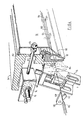
- Each filament gripping device 74 Situated at each end of the plenum member 40 is a filament gripping device 74, which are both connected to the base 34.
- Each filament gripping device comprises two opposed, parallel plates 75 interconnected at one end by means of a metal block 76 and at the other end by means of a metal rod 78.
- a pneumatic ram 80 passes through an aperture 72 in the block 76 and is secured therein.
- a piston rod 84 extends from the ram 80 and has an elongate metal head 86 of generally triangular cross-section secured thereto. Upon extension of the ram 80, the head 86 is adapted to engage between two parallel rods 88, the rods being secured between each of two metal brackets 90.
- the brackets are constrained, by virtue of elongate apertures 92 in the plates 74, to move in a direction parallel to the direction of motion of the head 86, and the brackets 90 and the rods 88 are biassed to lie in the position shown in Fig. 6 with the brackets engaging the edge of the apertures 92 nearest the pneumatic cylinder 80, by virtue of two helical tension springs 94 extending between a respective bracket 90 and the metal block 76.
- a third plate 96 extends between two long edges of the plates 74, and in use is situated adjacent the associated filament laying device 26a, 26b, 26c, 26d.
- the plate 96 is provided with a cut-out 98 having a bulbous portion smoothly merging into an elongate aperture.
- the filament gripping device is adapted to grip a filament which passes through the lobed portion of the aperture in the plate 96 by extending the ram 80 so that the filament is trapped between the head 86 and the two rods 88. Further extension of the ram 80 causes the filament to be pulled downwardly through the elongate portion of the aperture 98 against the force of the tension springs 94.
- each filament gripping device 74 is mounted with the direction of motion of the ram 80 inclined to the elongate axis of the plenum member 40, the filament gripping devices at opposite ends of the plenum member being inclined in opposite directions.
- the apparatus includes a conventional filament air gun 100, such as those used in conventional air weaving looms, which is adapted to project a filament 102 along the elongate plenum chamber 54. The passage of the filament 102 is aided by a plural ity of jets 104 (of which two are shown in the drawings) which extends into the plenum chamber 54.
- the apparatus also includes a filament cutter 106 comprising a fixed blade 108 and a moving blade 110, the cutter being conventional and known to those skilled in the art.
- the liquid plastics solution is applied to the sheet of backing paper 12 by means of the roller 14.
- the coated sheet then passes over roller 16 whereupon it encounters the first transverse filament applying device 26a.
- the air gun 100 shoots a fixed length of filament 102 through the bulbous portion of the aperture in the adjacent filament gripping device 74 and into the elongate plenum chamber 54.
- the air gun gives a single blast of air but a fixed length of filament is always shot from the air gun since the filament is dispensed from a filament accumulator which only allows a certain length of filament to be dispensed.
- the passage of the filament through the plenum chamber is aided by the plurality of jets 104 which aids the passage of the filament and also helps to reduce turbulence in the chamber.
- the filament is thus rapidly projected into the plenum chamber and extends out of the both ends thereof.
- the cutter 106 is then operated to severe the filament, and the two filament gripping devices 74 are immediately operated after the severing has taken place. It should be noted that in this position, the plenum member is in a closed position, as illustrated in Fig. 3.
- the pneumatic rams 80 are actuated to trap opposite ends of the filament between the heads 86 of triangular cross-section and the two movable parallel bars 88.
- the flap actuating plate 56 is pivoted by means of the push rods 64, due to rotation of the cams 72, and the flap 52 is thereby pivoted away from the relatively rigid base portion 50, forming an elongate aperture along the whole length of the plenum member 40.
- the continued motion of the pneumatic rams 80 then causes the filament to be moved downwardly, and into contact with the liquid plastics situated on the surface of the backing paper 12.
- the filament is placed under tension as it is laid onto the plastics. This produces a very straight clamped filament and allows the filament to be positioned accurately on the liquid plastics. Moreover, the tensioning of the filament reduces the tendency for the filament to "balloon".
- consecutive transverse filament laying devices are positioned to lay transverse filaments, one after the other.
- longitudinal or warp threads are applied to the coated surface of the backing paper 12 by passing a plurality of parallel filaments over a roller 20 and laying the filaments onto the plastics surface, as seen in Fig. 7.
- this is done at a direction-changing roller 20 over which the sheet of backing paper passes, and the angle of inclination y1 of the threads w1 to the portion of the sheet upstream of the rolller 20 is less than the change in angle x1 of the upstream and downstream portions, so that the threads are firmly pressed under tension into the liquid plastics.
- Two further transverse filament laying devices 26c, 26d and one warp thread laying roller 24 are subsequently provided to lay down further reinforcing filaments.
- the sheet is advanced for further processing to cure the liquid plastics.
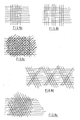
- filament patterns such as those illustrated in Figs. 8(a) and 9(b) may be produced, by appropriate timing of the application of the filaments and appropriate relative movement between the substrate (the plastic coated paper backing sheet) and the transverse filament laying apparatus.
- the transverse filament laying apparatus movable, for example by arranging for it to pivot about its centrepoint, the filament patterns shown in Figs. 8(c), 8(d) and 8(e) may be produced.
- the ability to produce different filament patterns allows the properties of the finished sheet to be accurately predetermined, and a sheet may be given predetermined properties by applying an appropriate reinforcing filament pattern thereto.
- Figs. 8(c) to 8(e) are shown as having a warp yarn, this may be dispensed with, and all the filaments may be laid down by using a movable, e.g. a pivotable apparatus in accordance with the present invention.
- the invention is not restricted to the details of the foregoing embodiment.
Landscapes
- Engineering & Computer Science (AREA)
- Textile Engineering (AREA)
- Treatment Of Fiber Materials (AREA)
- Laminated Bodies (AREA)
Abstract
A method and apparatus for laying down a weft filament. The weft yarns are propelled over a moving substrate, whereupon they are clamped and pulled down into the substrate. The apparatus propels the filaments (102) through an elongate hollow chamber (54) where they are clamped by clamping means (74). They are then transferred from the chamber onto the substrate. By pivotting the apparatus the angles at which the filaments can be layed onto the substrate can be carefully controlled enabling hitherto unobtainable products to be produced.
Description
- The present invention relates to a method and apparatus for laying a filament, and in particular, but not exclusively, to a method and apparatus for laying a weft yarn onto a substrate on which the weft yarn is to be secured.
- One application where it is necessary to lay a weft yarn onto a substrate occurs in the manufacture of reinforced plastics sheeting, the plastics sheeting being reinforced with a first set of fibres arranged perpendicularly to a second set of fibres.
- The known method for producing such a reinforced sheet is to first apply the plastics to a paper backing sheet withdrawn from a storage roll, the plastics being applied in liquid form, usually in the form of a solution. Reinforcing weft fibres are then laid across the width of the backing paper onto the liquid plastics, and are embedded therein. This is conventionally done by means of a travelling head which traverses across the width of the backing sheet and which lays down a weft yarn which sinks into, and becomes embedded in, the liquid plastics. By traversing backwards and forwards, a series of weft yarns is produced. However, in order position the yarns perpendicularly to the direction of motion of the travel of the backing sheet, it is necessary for the travelling head to traverse at a precisely calculated angle to the direction of motion of the paper, otherwise the threads will not be perpendicular to the length of the finished product. Also, this process is necessarily slow since in order to obtain reasonable accuracy the travelling head must not travel too quickly. It is possible to speed up the process by having a plurality of travelling heads, each dispensing its own weft yarn, but the cost of such apparatus is significantly increased. Moreover, the problem with all such travelling heads is that the resultant yarn laid down onto the plastics is not particularly accurate, in that the spacings between adjacent weft yarns can vary by several millimetres, perhaps as much as 5 mm in either direction from the correct location. This does not cause too much of a problem when the spacing of adjacent weft yarns is intended to be relatively large, but if the spacing of adjacent weft yarns becomes smaller, then the error involved in using the above apparatus becomes significant.
- Once the weft yarns are laid onto the plastics, a series of parallel, equally- spaced warp yarns extending parallel to the direction of motion of the backing paper, are laid down on top of the weft yarns and onto the plastics, in which they become embedded. The construction is subsequently passed through various further treatments and drying stages to produce the finished product.
- As stated above, in order to achieve reasonable speed, it is necessary to have a plurality of dispensing heads, and even so the accuracy obtained with the prior art devices is not good.
- It is an object of the present invention to provide an apparatus and method for laying a filament onto a substrate, which will enable the filament to be applied rapidly and accurately.
- In accordance with a first aspect of the present invention, an apparatus for laying a filament onto a substrate comprises compressed gas projection means for projecting the filament across the substrate, an elongate hollow chamber spaced from the substrate into which the filament is projected, the chamber having a closeable elongate aperture along its length, means for opening and closing the elongate aperture, clamping means situated adjacent each end of the elongate chamber for clamping the projected filament when in the closed chamber, and displacement means for displacing the clamped filament through the opened elongate aperture of the chamber onto the substrate.
- Such an apparatus allows rapid laying of the filament by virtue of the compressed gas projection means, and the filament is laid accurately by virtue of the fact that it is clamped in position and then displaced into engagement with the substrate.
- Preferably, the apparatus further comprises severing means for severing the filament to be laid down from the supply of filament.
- In a preferred embodiment, the clamping means and/or the displacement means are adapted to apply a tension to the clamped filament before application onto the substrate.
- The clamping means and the displacement means may comprise a movable clamping head which is movable into abutment with a clamping base, to clamp the filament therebetween. Preferably, the clamping base is movable, against the force of a resiliently deformable member, such that the clamped filament may be moved towards the substrate through the opened aperture in the elongate hollow chamber.
- There may be a plurality of apparatus in accordance with the first aspect of the present invention, arranged to apply filaments consecutively to a substrate.
- The or each apparatus may be movable, for example pivotally mounted, which enables filaments to be applied to the substrate at different angles.
- In a preferred embodiment, the aperture in the elongate hollow chamber may be opened and closked by means of a movable, preferably flexible, flat. The flap may be resiliently deformable and may be integrally formed with the elongate hollow chamber.
- In accordance with a second aspect of the present invention, a method of laying a filament onto a substrate comprises projecting the filament through an elongate hollow chamber spaced apart from the substrate, clamping the filament above the substrate when inside the chamber and displacing the clamped filament through an opened elongate, closeable aperture in the hollow member onto the substrate.
- Preferably, the filament is projected by means of compressed gas. Also, in a preferred embodiment, a tension is applied to the clamped filament before it is displaced onto the substrate.
- In accordance with a third aspect of the present invention, a method of applying one or more filaments on to a moving sheet comprises passing the moving sheet over a roller or other direction-changing device and laying the or each filament onto the sheet at, or in the vicinity of, the direction-changing device, the angle of inclination of the or each filament to be layed onto the sheet with respect to the portion of the sheet upstream of the direction-changing device being less than the angle through which the direction of the sheet is changed.
- By way of example only, a specific embodiment of the present invention will now be described, with reference to the accompanying drawings, in which:-
- Fig. 1 is a diagrammatic perspective view of an apparatus for laying intersecting fibres onto a continuously fed liquid-plastics substrate;
- Fig. 2 is a front elevation of a device in accordance with the present invention used to lay filaments across the substrate;
- Fig. 3 is a perspective view, partly cutaway, of one end of the device shown in Fig. 2, in a first, closed position;
- Fig. 4 is a perspective view, partly cutaway, of one end of the device shown in Fig. 2, in the open position;
- Fig. 5 is a cross-sectional side elevation of the device of Fig. 2;
- Fig. 6 is a perspective detail view of one portion of the device of Fig. 2;
- Fig. 7 is a diagrammatic cross-sectional side elevation of the apparatus for laying of the warp filaments, in accordance with the present invention; and
- Figs. 8(a) to 8(e) are diagrammatic views of some filament patterns which may be producd by means of the present invention.
- Referring firstly to Fig. 1, there is illustrated an apparatus for forming a plastics sheet reinforced with filaments extending along and across the sheet. The apparatus comprises a dispensing
roller 10 from which a continuous sheet ofbacking paper 12 is dispensed. One surface of thebacking paper 12 is coated with a liquid plastics coating, in the form of plastics dissolved in a solvent, by means of anapplication roller 14. The coated backing paper then passes over a first direction-changingroller 16 and over four further direction-changingrollers device 26a to 26d, illustrated schematically in Fig. 1, for laying down afilament 28 across the coated backing paper onto the liquid plastics coating, the filament extending in a direction substantially perpendicular to the direction of motion of the coatedbacking paper 12. - In between the second and third, 26b and 26c, and after the fourth, 26d, transverse filament laying devices are situated warp
filament laying rollers longitudinal warp filaments 32 to lie in a direction substantially parallel to the direction of motion of the coatedbacking paper 12. - As best seen in Fig. 8, the rollers are arranged to divert the direction of motion of the coated
backing paper 12. In particular, themiddle roller 20 and thefinal roller 24 are adapted to divert the plane of the paper through angles x₁ and x₂ respectively. It can also be seen that the longitudinal orwarp threads 32 define angles y₁ and y₂, such that y₁ < x₁ and y₂ < x₂. In this way, as the warp threads are laid onto the coated substrate, they are pressed firmly into the substrate at therollers - The device for applying the transverse filaments is shown in more detail in Figs. 2 to 6. The device comprises a
metal base 34 comprising a planarupper section 36 and a planarlower section 38 extending perpendicularly to theupper section 36. An elongateflexible plenum member 40, made out of, for example, Neoprene (Trade Mark) projects beyond the end of theplanar member 38, and is secured thereto by means of an angled bracket 42 which is secured to theplanar member 38 by means of a bolt 44. One end of the bracket 42 fits into an elongate groove in the flexibleelongate plenum member 40. - The
plenum member 40 comprises an upper,solid portion 48 from which a relativelyrigid flap 50 depends downwardly. The opposite side of the plenum member is provided with athinner flap 52, defining an elongate plenum chamber 54, which is bulbous in cross-section, therebetween. Theplenum member 40 naturally assumes the shape illustrated in Fig. 4, but can be constrained to assume the shape illustrated in Fig. 3 by means of aflap moving plate 56 which engages in anelongate groove 58 defined by anelongate rib 60 on the outer face of theflap 52. Theflap actuating member 56 is angled, such that its upper portion lies generally parallel to the plane of the upperplanar portion 36 of the base. The upper edge of theflap actuating plate 52 is seated in an elongate V-shaped groove 62 in theplanar portion 38 of the base. The flap actuatingplate 56 is pivotable about thegroove 62 by means of sixpush rods 64, secured to the plate by means ofbolts 66, the opposite ends of which push rods are each connected to arespective U-shaped bracket 68. A cam follower 70 is pivotally mounted between the free ends of eachbracket 68, and abuts against acam 72, as will be explained. Each of thebrackets 68 is provided with twoelongate apertures 74, one in each face of the U-shaped bracket, to allow movement relative to thecam shaft 76. By rotating the cam shaft, the cam followers engage with the cam and move the push rods and theflap actuating plate 56. The natural resilience of the flexible material forming theflap 52 removes the need for a separate spring. - Situated at each end of the
plenum member 40 is afilament gripping device 74, which are both connected to thebase 34. Each filament gripping device comprises two opposed,parallel plates 75 interconnected at one end by means of ametal block 76 and at the other end by means of ametal rod 78. Apneumatic ram 80 passes through anaperture 72 in theblock 76 and is secured therein. Apiston rod 84 extends from theram 80 and has anelongate metal head 86 of generally triangular cross-section secured thereto. Upon extension of theram 80, thehead 86 is adapted to engage between twoparallel rods 88, the rods being secured between each of twometal brackets 90. The brackets are constrained, by virtue ofelongate apertures 92 in theplates 74, to move in a direction parallel to the direction of motion of thehead 86, and thebrackets 90 and therods 88 are biassed to lie in the position shown in Fig. 6 with the brackets engaging the edge of theapertures 92 nearest thepneumatic cylinder 80, by virtue of two helical tension springs 94 extending between arespective bracket 90 and themetal block 76. Athird plate 96 extends between two long edges of theplates 74, and in use is situated adjacent the associatedfilament laying device plate 96 is provided with a cut-out 98 having a bulbous portion smoothly merging into an elongate aperture. - The filament gripping device is adapted to grip a filament which passes through the lobed portion of the aperture in the
plate 96 by extending theram 80 so that the filament is trapped between thehead 86 and the tworods 88. Further extension of theram 80 causes the filament to be pulled downwardly through the elongate portion of theaperture 98 against the force of the tension springs 94. - In use, each
filament gripping device 74 is mounted with the direction of motion of theram 80 inclined to the elongate axis of theplenum member 40, the filament gripping devices at opposite ends of the plenum member being inclined in opposite directions. Also, the apparatus includes a conventionalfilament air gun 100, such as those used in conventional air weaving looms, which is adapted to project afilament 102 along the elongate plenum chamber 54. The passage of thefilament 102 is aided by a plural ity of jets 104 (of which two are shown in the drawings) which extends into the plenum chamber 54. The apparatus also includes afilament cutter 106 comprising a fixedblade 108 and a movingblade 110, the cutter being conventional and known to those skilled in the art. - In use, the liquid plastics solution is applied to the sheet of backing
paper 12 by means of theroller 14. The coated sheet then passes overroller 16 whereupon it encounters the first transversefilament applying device 26a. At predetermined intervals, theair gun 100 shoots a fixed length offilament 102 through the bulbous portion of the aperture in the adjacentfilament gripping device 74 and into the elongate plenum chamber 54. The air gun gives a single blast of air but a fixed length of filament is always shot from the air gun since the filament is dispensed from a filament accumulator which only allows a certain length of filament to be dispensed. The passage of the filament through the plenum chamber is aided by the plurality ofjets 104 which aids the passage of the filament and also helps to reduce turbulence in the chamber. The filament is thus rapidly projected into the plenum chamber and extends out of the both ends thereof. Thecutter 106 is then operated to severe the filament, and the twofilament gripping devices 74 are immediately operated after the severing has taken place. It should be noted that in this position, the plenum member is in a closed position, as illustrated in Fig. 3. Immediately after the cutter has severed the filament, thepneumatic rams 80 are actuated to trap opposite ends of the filament between theheads 86 of triangular cross-section and the two movableparallel bars 88. As soon as the filaments are gripped, theflap actuating plate 56 is pivoted by means of thepush rods 64, due to rotation of thecams 72, and theflap 52 is thereby pivoted away from the relativelyrigid base portion 50, forming an elongate aperture along the whole length of theplenum member 40. The continued motion of thepneumatic rams 80 then causes the filament to be moved downwardly, and into contact with the liquid plastics situated on the surface of thebacking paper 12. It will also be noted that due to the inclination of thegripping devices 74, the filament is placed under tension as it is laid onto the plastics. This produces a very straight clamped filament and allows the filament to be positioned accurately on the liquid plastics. Moreover, the tensioning of the filament reduces the tendency for the filament to "balloon". - As seen in Fig. 1, consecutive transverse filament laying devices are positioned to lay transverse filaments, one after the other. In between certain pairs of the devices, longitudinal or warp threads are applied to the coated surface of the
backing paper 12 by passing a plurality of parallel filaments over aroller 20 and laying the filaments onto the plastics surface, as seen in Fig. 7. As mentioned previously, this is done at a direction-changingroller 20 over which the sheet of backing paper passes, and the angle of inclination y₁ of the threads w₁ to the portion of the sheet upstream of therolller 20 is less than the change in angle x₁ of the upstream and downstream portions, so that the threads are firmly pressed under tension into the liquid plastics. Two further transversefilament laying devices 26c, 26d and one warp thread laying roller 24 (similar toroller 20, with angle y₂ less than angle x₂) are subsequently provided to lay down further reinforcing filaments. When all the filaments have been applied, the sheet is advanced for further processing to cure the liquid plastics. - By using the apparatus and method of the present invention, filament patterns such as those illustrated in Figs. 8(a) and 9(b) may be produced, by appropriate timing of the application of the filaments and appropriate relative movement between the substrate (the plastic coated paper backing sheet) and the transverse filament laying apparatus. However, by mounting the transverse filament laying apparatus movable, for example by arranging for it to pivot about its centrepoint, the filament patterns shown in Figs. 8(c), 8(d) and 8(e) may be produced. These are only examples of filament patterns which may be produced, and it will be appreciated that many other different patterns of filaments may be produced with the apparatus and method of the present invention. The ability to produce different filament patterns allows the properties of the finished sheet to be accurately predetermined, and a sheet may be given predetermined properties by applying an appropriate reinforcing filament pattern thereto.
- Indeed, although Figs. 8(c) to 8(e) are shown as having a warp yarn, this may be dispensed with, and all the filaments may be laid down by using a movable, e.g. a pivotable apparatus in accordance with the present invention.
- The invention is not restricted to the details of the foregoing embodiment. In particular, there may be a plurality of transverse filament laying apparatus arranging one after the other, as illustrated schematically in Fig. 7, which lay down filaments consecutively.
Claims (14)
1. An apparatus (26) for laying a filament (28) onto a substrate (12) characterised in that said apparatus (26) comprises a compressed gas projecting means (102) for projecting the filament (28) across the substrate (12), an elongate hollow chamber (54) spaced from the substrate (12) into which the filament (28) is projected, the chamber (54) having a closeable elongate aperture along its length, means (56) for opening and closing the elongate aperture, clamping means (74) situated adjacent each end of the elongate chamber (54) for clamping the projected filament (28) when in the closed chamber, and displacement means (80) for displacing the clamped filament (102) through the opened elongate aperture of the chamber onto the substrate.
2. An apparatus as claimed in claim 1, which further comprises severing means (106).
3. An apparatus as claimed in claim 1 or 2, in which the clamping means (74) and/or the displacement means (80) are adapted to apply a tension to the clamped filament (28).
4. An apparatus as claimed in any of the preceding claims, wherein the clamping means (74) and the displacement means (80) comprises a movable clamping head (86).
5. An apparatus as claimed in any preceding claim, wherein the means for opening and closing the elongate aperture is a flexible flap (52).
6. A method of laying a filament (28) onto a substrate (12), characterised in that said filament (28) is projected through an elongate hollow chamber (54) spaced apart from said substrate (12), clamped inside the chamber (54) above the substrate (12) and displaced through an open elongate closeable aperture in the hollow chamber (54) onto the substrate.
7. A method as claimed in claim 6, wherein the filament is projected by means of compressed gas.
8. A method as claimed in claim 6 or 7, wherein a tension is applied to the clamped filament (28) before it is displaced onto the substrate (12).
9. A method as claimed in claims 6 to 8, wherein the substrate (12) is a plastics sheet.
10. A method as claimed in claim 9, wherein said plastics sheet is reinforced.
11. A method of applying one or more filaments (28) onto a moving sheet (12), comprising passing the moving sheet (12) over a roller (16) or other direction changing device and laying the or each filament (28) onto the sheet (12) at, or in the vicinity of the direction changing device (16), characterised in that the angle of inclination of the or each filament (28) to be layed onto the sheet (12) with respect to the portion of the sheet (12) upstream of the direction changing device (16) is less than the angle through which the direction of the sheet is changed.
12. A sheet produced by the method of claim 11, in which the resulting product has a weft pattern in which some of the weft filaments are not substantially perpendicular to the direction in which the sheet travels.
13. A sheet produced by the method of claim 11, in which the resulting product has no warp filaments and a weft pattern in which some of the weft filaments are not substantially perpendicular to the direction in which the sheet travels.
14. A sheet as claimed in claim 12 or 13, in which the weft filaments are grouped and one group of weft filaments crosses over another set of weft filaments.
Applications Claiming Priority (2)
| Application Number | Priority Date | Filing Date | Title |
|---|---|---|---|
| GB8810564 | 1988-05-05 | ||
| GB888810564A GB8810564D0 (en) | 1988-05-05 | 1988-05-05 | Method & apparatus for laying filament |
Publications (2)
| Publication Number | Publication Date |
|---|---|
| EP0341032A2 true EP0341032A2 (en) | 1989-11-08 |
| EP0341032A3 EP0341032A3 (en) | 1990-07-04 |
Family
ID=10636353
Family Applications (1)
| Application Number | Title | Priority Date | Filing Date |
|---|---|---|---|
| EP89304423A Withdrawn EP0341032A3 (en) | 1988-05-05 | 1989-05-03 | Method and apparatus for laying a filament |
Country Status (4)
| Country | Link |
|---|---|
| US (1) | US4992123A (en) |
| EP (1) | EP0341032A3 (en) |
| JP (1) | JPH0243050A (en) |
| GB (1) | GB8810564D0 (en) |
Cited By (2)
| Publication number | Priority date | Publication date | Assignee | Title |
|---|---|---|---|---|
| FR2743821A1 (en) * | 1996-01-23 | 1997-07-25 | Berthiaud Christian | MESH NETWORK BASED ON NONWOVEN YARNS, METHOD AND INSTALLATION FOR OBTAINING THE SAME |
| DE102006025753A1 (en) * | 2006-05-31 | 2007-12-13 | Eads Deutschland Gmbh | Process for introducing reinforcing fibers into a semifinished textile product and semi-finished textile products with incorporated reinforcing fibers |
Families Citing this family (8)
| Publication number | Priority date | Publication date | Assignee | Title |
|---|---|---|---|---|
| US5269863A (en) * | 1990-09-24 | 1993-12-14 | Akzo Nv | Continuous process for the manufacture of substrates for printed wire boards |
| US5882473A (en) * | 1996-03-19 | 1999-03-16 | Bando Chemical Industries, Ltd. | Fabric positioning apparatus used in producing synchronous belt |
| US5971050A (en) * | 1996-11-27 | 1999-10-26 | Sedepro | Removable thread guide which receives threads projected onto a surface |
| US6167934B1 (en) | 1996-11-27 | 2001-01-02 | Sedepro | Removable thread guide which receives threads projected onto a surface |
| US5951815A (en) * | 1996-11-27 | 1999-09-14 | Sedepro | Removable thread guide which receives threads projected onto a surface |
| FR2756212A1 (en) * | 1996-11-27 | 1998-05-29 | Sedepro | REMOVABLE WIRE GUIDE, RECEIVING WIRES PROJECTED ON A SURFACE |
| FR2756213A1 (en) * | 1996-11-27 | 1998-05-29 | Sedepro | WIRE GUIDE WITH ADJUSTABLE BRAKE, RECEIVING WIRES PROJECTED ONTO A SURFACE |
| ATE460267T1 (en) * | 2006-11-02 | 2010-03-15 | Michelin Soc Tech | DETERMINING THE OPENING ANGLE OF THE Baffles USED IN A CONDUIT RACK THAT ACCOMMODATE CABLES PROJECTED ONTO A SURFACE |
Family Cites Families (9)
| Publication number | Priority date | Publication date | Assignee | Title |
|---|---|---|---|---|
| CA523494A (en) * | 1956-04-03 | W. Polley Robert | Machine for paying out and delivering parallel lengths of thread | |
| US3108028A (en) * | 1959-10-01 | 1963-10-22 | Sprunck Gerhard | Method and apparatus for the reinforcement of glass fibre webs or mats |
| US3690990A (en) * | 1970-02-10 | 1972-09-12 | Yasuhiro Izumi | Apparatus for manufacture of non-woven fabric |
| CH552695A (en) * | 1972-02-21 | 1974-08-15 | Zbrojovka Vsetin Np | DEVICE FOR SHOT ENTRY ON A THUS WEAVING MACHINE. |
| CH586298A5 (en) * | 1975-02-18 | 1977-03-31 | Saurer Ag Adolph | Weft-propelling gas jet guide - has telescopic parts displaceable to form a closed channel during weft insertion (OE 15.6.76) |
| EP0016356A1 (en) * | 1979-03-15 | 1980-10-01 | Deutsche Solvay-Werke Gmbh | Process and device for manufacturing textile wall coverings or wall coverings of material resembling textile |
| DE3140480C2 (en) * | 1981-10-12 | 1984-04-26 | Karl Mayer Textil-Maschinen-Fabrik Gmbh, 6053 Obertshausen | Warp knitting machine with a weft thread magazine and a fleece feed device |
| FR2599297B1 (en) * | 1986-06-02 | 1988-08-12 | Michelin & Cie | PROCESS AND MACHINE FOR MANUFACTURING A REINFORCEMENT FOR TIRES |
| US4867825A (en) * | 1988-02-23 | 1989-09-19 | Bay Mills Limited | Machine and process for forming crosswise filaments for non-woven fabric and product of the process |
-
1988
- 1988-05-05 GB GB888810564A patent/GB8810564D0/en active Pending
-
1989
- 1989-05-02 JP JP1113584A patent/JPH0243050A/en active Pending
- 1989-05-03 US US07/346,740 patent/US4992123A/en not_active Expired - Fee Related
- 1989-05-03 EP EP89304423A patent/EP0341032A3/en not_active Withdrawn
Cited By (3)
| Publication number | Priority date | Publication date | Assignee | Title |
|---|---|---|---|---|
| FR2743821A1 (en) * | 1996-01-23 | 1997-07-25 | Berthiaud Christian | MESH NETWORK BASED ON NONWOVEN YARNS, METHOD AND INSTALLATION FOR OBTAINING THE SAME |
| DE102006025753A1 (en) * | 2006-05-31 | 2007-12-13 | Eads Deutschland Gmbh | Process for introducing reinforcing fibers into a semifinished textile product and semi-finished textile products with incorporated reinforcing fibers |
| DE102006025753B4 (en) * | 2006-05-31 | 2010-02-04 | Eads Deutschland Gmbh | Method for introducing reinforcing fibers into a semifinished textile product, semi-finished textile product with incorporated reinforcing fibers, and fiber composite component |
Also Published As
| Publication number | Publication date |
|---|---|
| EP0341032A3 (en) | 1990-07-04 |
| GB8810564D0 (en) | 1988-06-08 |
| JPH0243050A (en) | 1990-02-13 |
| US4992123A (en) | 1991-02-12 |
Similar Documents
| Publication | Publication Date | Title |
|---|---|---|
| US4325999A (en) | Bias fabric | |
| EP0341032A2 (en) | Method and apparatus for laying a filament | |
| US8479778B2 (en) | Weaving machine and method for three-dimensional weaving | |
| US5308424A (en) | Multiaxial nonwoven fabric, and method of making the same | |
| EP0158933B1 (en) | Method and apparatus for passing thread through member formed with opening | |
| US5394906A (en) | Method and apparatus for weaving curved material preforms | |
| EP0382761B1 (en) | Improvements in or relating to fabric production | |
| EP0322821A1 (en) | Method of and apparatus for weaving a three-dimensional article | |
| US5924459A (en) | Air jet machine and diagonal Z loop fabric pattern for three-dimensional fabric | |
| EP0064976A1 (en) | WANDING TAPE MECHANISM. | |
| KR0136662B1 (en) | Method and apparatus for providing a thread to a support and a reinforcing ply accordingly | |
| US4401493A (en) | Reinforced structures | |
| JPS6240455B2 (en) | ||
| US4405395A (en) | Reinforced structures | |
| IE51767B1 (en) | Reinforced structures | |
| US6659138B2 (en) | Device for producing a tape having a curve, especially a curved flat line compound | |
| DE2323732A1 (en) | YARN HANDLING MECHANISM FOR TEXTILE MACHINERY, IN PARTICULAR LOOM | |
| US5074950A (en) | Weaving machine for making fiberglass grating with improved tension control of fiberglass strands during layup | |
| US3345232A (en) | Method and apparatus for making criss-cross material | |
| GB2085494A (en) | Reinforced structures | |
| FI81616B (en) | Automated seam machine for cloth ribbons | |
| DE2242617C3 (en) | Apparatus for making carpets, in particular patterned carpets | |
| BE1017456A3 (en) | A DEVICE FOR MAINTAINING THE FABRIC WIDTH OF A FABRIC ON A WEAVING MACHINE. | |
| GB2085496A (en) | Reinforced structures | |
| GB2085495A (en) | Reinforced structures |
Legal Events
| Date | Code | Title | Description |
|---|---|---|---|
| PUAI | Public reference made under article 153(3) epc to a published international application that has entered the european phase |
Free format text: ORIGINAL CODE: 0009012 |
|
| AK | Designated contracting states |
Kind code of ref document: A2 Designated state(s): AT BE CH DE ES FR GB GR IT LI LU NL SE |
|
| PUAL | Search report despatched |
Free format text: ORIGINAL CODE: 0009013 |
|
| AK | Designated contracting states |
Kind code of ref document: A3 Designated state(s): AT BE CH DE ES FR GB GR IT LI LU NL SE |
|
| 17P | Request for examination filed |
Effective date: 19900720 |
|
| STAA | Information on the status of an ep patent application or granted ep patent |
Free format text: STATUS: THE APPLICATION HAS BEEN WITHDRAWN |
|
| 18W | Application withdrawn |
Withdrawal date: 19901210 |