EP0340682B1 - Photografische Kamera und Filmkassette mit einer Verteilervorrichtung für eine Flüssigkeit - Google Patents
Photografische Kamera und Filmkassette mit einer Verteilervorrichtung für eine Flüssigkeit Download PDFInfo
- Publication number
- EP0340682B1 EP0340682B1 EP89107805A EP89107805A EP0340682B1 EP 0340682 B1 EP0340682 B1 EP 0340682B1 EP 89107805 A EP89107805 A EP 89107805A EP 89107805 A EP89107805 A EP 89107805A EP 0340682 B1 EP0340682 B1 EP 0340682B1
- Authority
- EP
- European Patent Office
- Prior art keywords
- film
- pressure
- film unit
- cassette
- processing liquid
- Prior art date
- Legal status (The legal status is an assumption and is not a legal conclusion. Google has not performed a legal analysis and makes no representation as to the accuracy of the status listed.)
- Expired - Lifetime
Links
- 239000007788 liquid Substances 0.000 title claims description 72
- 238000012545 processing Methods 0.000 claims description 56
- 230000007480 spreading Effects 0.000 claims description 10
- 238000003892 spreading Methods 0.000 claims description 10
- 238000009826 distribution Methods 0.000 claims description 8
- 230000015572 biosynthetic process Effects 0.000 claims description 6
- 230000001276 controlling effect Effects 0.000 claims 2
- 230000001105 regulatory effect Effects 0.000 claims 2
- 238000011144 upstream manufacturing Methods 0.000 claims 1
- 238000003860 storage Methods 0.000 description 9
- 230000002411 adverse Effects 0.000 description 3
- 238000000034 method Methods 0.000 description 3
- 230000003247 decreasing effect Effects 0.000 description 2
- 230000000694 effects Effects 0.000 description 2
- 239000012530 fluid Substances 0.000 description 2
- 238000005213 imbibition Methods 0.000 description 2
- 230000002829 reductive effect Effects 0.000 description 2
- 238000005452 bending Methods 0.000 description 1
- 230000008901 benefit Effects 0.000 description 1
- 239000000470 constituent Substances 0.000 description 1
- 238000010276 construction Methods 0.000 description 1
- 238000013461 design Methods 0.000 description 1
- 238000011161 development Methods 0.000 description 1
- 230000018109 developmental process Effects 0.000 description 1
- 238000009792 diffusion process Methods 0.000 description 1
- 238000005286 illumination Methods 0.000 description 1
- 230000000977 initiatory effect Effects 0.000 description 1
- 230000000670 limiting effect Effects 0.000 description 1
- 230000036961 partial effect Effects 0.000 description 1
- 238000002360 preparation method Methods 0.000 description 1
- 230000008569 process Effects 0.000 description 1
- 230000004044 response Effects 0.000 description 1
- 238000012546 transfer Methods 0.000 description 1
- 238000009827 uniform distribution Methods 0.000 description 1
Images

Classifications
-
- G—PHYSICS
- G03—PHOTOGRAPHY; CINEMATOGRAPHY; ANALOGOUS TECHNIQUES USING WAVES OTHER THAN OPTICAL WAVES; ELECTROGRAPHY; HOLOGRAPHY
- G03B—APPARATUS OR ARRANGEMENTS FOR TAKING PHOTOGRAPHS OR FOR PROJECTING OR VIEWING THEM; APPARATUS OR ARRANGEMENTS EMPLOYING ANALOGOUS TECHNIQUES USING WAVES OTHER THAN OPTICAL WAVES; ACCESSORIES THEREFOR
- G03B17/00—Details of cameras or camera bodies; Accessories therefor
- G03B17/48—Details of cameras or camera bodies; Accessories therefor adapted for combination with other photographic or optical apparatus
- G03B17/50—Details of cameras or camera bodies; Accessories therefor adapted for combination with other photographic or optical apparatus with both developing and finishing apparatus
- G03B17/52—Details of cameras or camera bodies; Accessories therefor adapted for combination with other photographic or optical apparatus with both developing and finishing apparatus of the Land type
Definitions
- the invention relates to photographic apparatus including an instant or self-developing type camera and a film assemblage which interrelate with each other to control the thickness and/or shape of a layer of processing liquid to be spread between layers of an exposed film unit.
- the invention is directed to certain improvements in the relationship between photographic film assemblages of the self-developing type and the cameras (or camera backs) with which they are adapted to be used. More specifically, the invention relates to a relationship between the two which allows for a greater spacial juxtapositioning between processing liquid spread control features on a film cassette and the liquid spreading and control structures in a camera.
- an important step in the processing of an exposed instant or self-developing type film unit is the spreading of a processing liquid between predetermined layers of the film unit to initiate the formation of a visible image therein via a diffusion transfer process.
- a processing liquid it is desirable that the processing liquid be spread such that it covers the entire photoexposed area of the film unit in a thin layer of predetermined uniform thickness.
- a typical film unit includes a photosensitive element, an image-receiving element which may be superposed on the photosensitive element subsequent to exposure or may be transparent and predisposed on the photosensitive element such that exposure may be made through the image-receiving element, and a rupturable pod or container of processing liquid located at one end of the two elements.
- the film units are arranged in stacked relation within a film cassette which is adapted to be inserted into the receiving chamber of an appropriate camera to locate an endmost film unit in the stack in position for exposure.
- the endmost film unit is extracted from the film cassette and is advanced, pod end first, between a pair of pressure-applying members mounted within the camera.
- the pressure-applying members exert a compressive force on the pod causing it to rupture and discharge the liquid between predetermined layers of the film unit, e.g., between the exposed photosensitive element and the superposed image-receiving element.
- Continued advancement of the film unit between the pressure-applying members results in the liquid being advanced along a liquid wave front toward the trailing end of the film unit such that it is progressively distributed over the photoexposed area of the film unit.
- the uniformity of the liquid layer is, to a large degree, determined by the initial shape of the liquid wave front.
- the wave front be disposed in a substantially straight line which extends outwardly to the lateral margins of the area and is oriented in a direction that is normal to the direction of film advancement between the pressure-applying members.
- the wave front shape is also influenced by the velocity at which the film unit is advanced through the pressure-applying members, the amount of compressive pressure exerted on the film unit, and the resistance to liquid flow at the interfaes between the liquid and the superposed film unit elements.
- One of the most commonly observed spread shapes is a tongue shape wherein the wave front progresses more rapidly at the central portion of the photoexposed or image-forming area than out at the lateral margins.
- This condition may be caused by an uneven distribution of liquid upon initial discharge from the pod, i.e., more liquid being concentrated at the center of the film unit than out at its edges.
- the corners of the image-forming area at the trailing end of the film unit will be coated with a layer of liquid of reduced depth or thickness, thus, possibly adversely affecting the film unit's sensitometry or not be coated at all.
- the film unit is configured as including first and second superposed sheets, at least one of which comprises photosensitive constituents, whose lateral edges are permanently secured to each other by longitudinally extending rails. Because these sheets are bound at their lateral edges, the sheets tend to separate more in the center of the film unit than out at the lateral margins in response to the processing liquid being spread therebetween. Thus, there is more resistance to the flow of the processing liquid at the edges of the film unit vis-a-vis its center section. Upon initial discharge of the liquid from its pod, it assumes a rearwardly extending tongue shape rather than proceeding toward the trailing end of the film unit along a uniform wave front.
- One method employed to compensate for a tongue-shaped wave front has been to provide excess liquid in the pod.
- Another method has been to equip the camera with spread control devices which serve to modify the shape of the liquid wave front during spreading.
- the spread control devices are designed to apply a second compressive force to the central portion of the film unit in the path of the mass of liquid discharged from the pod by the pressure-applying members. This serves to retard the central portion of the wave front and cause a flow of liquid in a direction transverse to the direction of film advancement. In this manner, the wave front is modified such that it is substantially straight and is oriented in a direction substantially normal to the parallel sides of the rectangular or square image-forming area.
- a major drawback with systems of the type shown and described in the patents listed above is that the control features located on the film cassette are formed on interior surfaces thereof and thus must be spaced relatively close to the pressure-applying means or spread rollers of the camera in order to be effective. This severely restricts the options available to a camera designer in the placement of the spread rollers relative to the film cassette. Further, if spreading of the processing liquid takes place substantially at the location where the film unit emerges from its cassette, then it is generally advisable that the film unit be maintained in a planar condition until processing of the image has been substantially completed. This is so as not to subject the layer of processing liquid to any external forces, such as may be caused by bending the film unit during its transport to a storage chamber or to the exterior of the camera.
- the present invention relates to a photographic apparatus of the type as disclosed in US-A-4 688 912.
- said second film advancing means which continue the movement of the endmost film unit in the second direction generally opposite to said first direction comprise pressure applying rollers functioning to spread the processing liquid across a layer of the exposed film unit to initiate formation of a visable image thereon.
- These pressure applying rollers continue the movement of the exposed film unit towards an imbibition chamber while simultaneously rupturing the container of processing liquid located on the leading end of the film unit and spreading its content between layers of the film unit.
- the exposed film unit emerges from between the pressure applying rollers the film unit is caught by a further film advancing member in form of a hook completing the movement into the imbibition chamber.
- the invention further relates to a photographic film cassette of the type as disclosed in above mentioned US-A-4 104 669.
- the second pressure applying means which assist equal distribution of the liquid are provided at the egress slot of the cassette provided in the leading wall of this cassette.
- These second pressure applying means which create a flow opposition pressure comprise an elongated bow-shaped bi-metallic strip which includes a pair of opposed supporting end-portions.
- the photographic apparatus in which this known cassette is used comprises pressure applying rollers the pressure gap whereof is provided in the same plane as the egress slot of the cassette and the film unit is advanced in this plane out of the photographic apparatus.
- the photographic apparatus adapted for the cassette of the present invention involves redirecting each film unit from a first direction to an opposite direction wherein the path of movement of the opposite direction is below the bottom wall of the cassette.
- the photographic apparatus of the invention further includes a pair of shafts, at least one of which is motor driven, each of which includes on its opposite ends a section of increased diameter which define opposite pairs of superposed edge rollers.
- These rollers are adapted to engage opposite margins of the endmost film unit so as to continue its movement in a first direction into an arcuate passageway which functions to redirect the endmost film unit in a second direction into the bite of another set of laterally spaced pairs of edge rollers.
- the latter edge rollers continue the movement of the exposed endmost film unit between a pressure plate and the processing liquid spread control means on the film cassette and then into the bite of a pair of elongate rollers.
- the elongate rollers are adapted to be driven in a direction so as to rupture a container of processing liquid attached to a leading end of the endmost film unit and spread its contents between layers of the film unit to initiate the formation of a visible image therein while simultaneously advancing the film unit into a lighttight storage chamber.
- the film unit is adapted to stay in the storage chamber until its emerging image is no longer susceptible to being adversely affected by being moved into the ambient light.
- the film unit may contain its own opacification system for preventing such exposure, in which case the storage chamber need not be lighttight or may be omitted and the film advanced directly to the exterior of the camera.
- the emerging processing liquid forms a wave which travels in a direction toward the pressure plate as well as from the leading end of the film unit to its trailing end.
- the pressure plate is biased against one major surface of the endmost film unit so as to move an opposite major surface of the film unit into engagement with the processing liquid spread control means formed in the external surface of the film cassette's bottom wall.
- the constraint applied to opposite sides of the advancing film unit by the pressure plate and the processing liquid spread control means acts to retard the wave's progress at intermediate portions of the wave, thus providing a wave fromt which is relatively linear and perpendicular to the direction of movement of the film unit through the spread rollers.
- a side wall of the film cassette is formed with a tab or protrusion which is adapted to engage a portion of a movably mounted structure for supporting the spread rollers, which structure locates the spread rollers in the path of movement that a film unit would take during its movement from the film cassette to the storage chamber.
- the precise location of the tab relative to the film cassette's bottom or top wall, or its thickness, is chosen so as to insure that the gap or bite between the superposed spread rollers occupies a predetermined relation to the path of movement of the film unit at a location immediately prior to the latter's leading edge engaging one of the spread rollers.
- the aforementioned relationship between the gap and the path of travel can be altered thus effectively increasing or decreasing the angle at which the film unit enters the gap thereby changing the thickness of the layer of processing liquid to be spread by the rollers.
- the path of travel of the film unit into the bite between the spread rollers is generally perpendicular to a plane containing the axes of the spread rollers, then any deviation from such path will result in a thinner thickness of processing liquid being spread between elements or layers of the film unit.
- the angle of entry of the film unit is not perpendicular to said plane, then any relative movement between the two towards a prependicular relationship will result in a thicker spread.
- An object of the invention is to provide a camera of the instant type with means for urging an exposed film unit into engagement with a processing liquid spread control means located on a exterior surface of a film cassette as a processing liquid is being spread between layers of the film unit.
- Another object of the invention is to provide a film cassette with means for locating a pair of camera mounted spread rollers having a gap therebetween relative to a path of travel to be taken by an exposed film unit of the instant type as it is moved into the gap thereby affecting the thickness of a layer of processing liquid to be spread between elements of the exposed film unit.
- Still another object of the invention is to provide a photographic film assemblage with a film cassette having means in an external surface thereof for cooperating with structure in a camera for controlling the distribution of a quantity of processing liquid between layers of an exposed film unit of the instant type.
- the invention accordingly comprises the structure possessing the construction, combination of elements and arrangement of parts which are exemplified in the following detailed disclosure, and the scope of the application of which will be indicated in the claims.
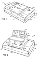
- the camera 10 includes a first or main housing 12 having a loading door 14 in a bottom wall thereof.
- the first housing 12 also includes front and rear walls 18 and 20, respectively, and end walls 22 and 24.
- the door 14 is pivotally connected to the end wall 22 of the main housing 12 by a hinge (not shown) which is generally parallel with the axis of the camera's objective lens 28 and perpendicular to the forward and rear walls 18 and 20.
- the main housing 12 further includes a top wall 30 having a pair of spaced flanges 32 and 34 extending upwardly therefrom so as to define a recess 36.
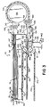
- the camera 10 further includes a second housing 38 which is pivotally coupled to the first housing 12 about an axis (not shown) which is generally parallel with the rear wall 20 for movement between an inoperative position (see Fig. 1), wherein it is nested within the recess 36, and its operative position, as shown in Fig. 2.
- the second housing 38 supports the aforementioned objective lens 28, a shutter assembly, and a photocell window 40.
- a top wall 42 of the second housing includes a recess 44 which is adapted to receive a third housing 46 of the camera 10 when the camera is being collapsed or folded.
- the third housing 46 is pivotally coupled to the rear wall 20 of the first housing 12 about a horizontal axis (not shown) which is generally parallel with the rear wall 20.
- the third housing 46 is provided with a recess 50 for pivotally receiving therein a fourth housings 52.
- the fourth housing 52 supports a source of artificial illumination such as a strobe 54 and a ranging window 56.
- the fourth housing 52 as well as the second and third housings 38 and 46, is biased into the erect position shown in Fig. 2. Further, the fourth section 52 is adapted to be nested within the recess 50 prior to the third housing 46 being moved into the recess 44.
- actuation of an exposure cycle initiation button 58 located within a recess in the top wall 30 of the first housing 12 is effective to cause image bearing light rays to enter the camera 10 via the lens 28 and be reflected downwardly by a mirror (not shown) onto a film unit.
- the camera 10 includes a film chamber 60 which is accessible via the loading door 14.
- the film chamber 60 is adapted to receive a film assemblage 70.
- the film chamber 60 is defined in part by a wall 62 which functions to locate a film cassette 72 of the assemblage 70 in position for the sequential exposure of a plurality of film units 74 stacked therein.
- the film assemblage 70 includes, in addition to the film cassette 72 and the film units 74, biasing means (not shown) for resiliently urging the stack of film units 74 toward a forward wall 76 of the film cassette 72.
- the forward wall 76 is provided with a generally rectangular shaped exposure aperture 78 which is adapted to be located in alignment with a correspondingly shaped aperture 64 located in the wall 62.
- the forward wall 76 cooperates with a pair of side walls 80 and 82, leading and trailing end walls 84 and 86, and a bottom wall 88, to define a chamber for receiving the stack of film units 74.
- the aforementioned biasing means is located between the bottom wall 88 and an adjacent endmost film unit 74 so as to urge the opposite endmost film unit 74 in the stack against the interior surface of the forward wall 76 with 1) its photosensitive layer 90 (see Fig. 5) located in alignment with the exposure aperture 78, 2) its leading end located in position to be moved through an elongate egress 92 in the cassette's leading end wall 84, and 3) its trailing end located adjacent the trailing end wall 86.
- the leading end of each film unit 74 is provided with a pod or container 94 of processing liquid 96 (see Fig. 5) and the trailing end of each film unit is formed with a trap 98 for receiving any excess processing liquid 96.
- a protuberance 100 Extending downwardly from the bottom wall 88 and integrally formed therewith is a protuberance 100 which functions to control the distribution of the processing liquid to be spread between layers of an exposed film unit.
- the protuberance 100 slopes downwardly and rearwardly as it extends from the leading end wall 84 to its left terminus 102 (as viewed in Fig. 3) to define a surface 104 having upwardly sloping lateral ends 106 and 108 (see Fig. 5).
- the side wall 84 of the film cassette 72 has a tab 110 which extends outwardly therefrom.
- the tab 110 is adapted to cooperate with camera structure to adjust the location of a pressure-generating gap relative to a path of travel of an exposed film unit as the latter enters the gap so as to increase or decrease the thickness of a layer of processing liquid to be spread between layers or elements of the film unit.
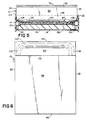
- the camera 10 includes a structure 112 for supporting 1) a first pressure-applying means in the form of elongate spread rollers 114 and 116, and 2) a second pressure-applying means in the form of a laterally extending plate 118.
- the opposite ends of the spread rollers 114 and 116 are rotatably supported in one end of a pair of laterally spaced arms 120 and 122 so as to define a pressure generating gap 124 therebetween.
- the roller 116 is mounted for movement toward and away from the roller 114.
- the opposite ends of the arms 120 and 122 are rotatably supported on a cylindrical rod 126.
- the arm 120 is shown in phantom lines so as to provide a better view of the camera's first and second pressure-applying means and the surfaces 104 and 106 of the protuberance 100.
- the pressure generating gap 124 is shown as being located in alignment with a path of travel that an exposed film unit 74 would take as it moves from the film cassette 72 to a film storage chamber 128, said path of travel being indicated by the line 130.
- the plate 118 extends between the ends of another pair of arms 132 and 134, the opposite ends of which are also rotatably supported by the rod 126.
- the second pressure-applying means is adapted to be independently rotated about the rod 126 without affecting the movement of the first pressure-applying means.
- Suitable means such as a spring schematically shown in Fig. 3 at 136, is provided for resiliently biasing the arm(s) 134 and 136 in a clockwise direction against a stop (not shown).
- a separate spring 138 is provided for resiliently biasing the arm(s) 132 and 134 in a clockwise direction into engagement with a stop 140. The force of the spring 138 may be increased or decreased by moving an adjusting cam 142 to the left or right, respectively, as shown in Fig. 3.
- the tab 110 engages an upwardly extending portion 144 of the arm 120 and causes the first pressure-applying means (arms 118, 120 and rollers 116 and 112) to be rotated in a counterclockwise direction about the rod 126 until the film cassette 72 is in the position shown in Fig. 3 and the gap 124 properly located relative to the path of travel 130; the degree of such rotation being a function of the thickness of the tab 110 or its location on the side wall of the film cassette 72, which in turn is a function of a predetermined desired thickness for a layer of processing liquid 96 to be spread between layers of the particular film units located in the film cassette 72.
- a second relationship is being established, namely, the juxtapositioning of the protuberance 100 on the bottom wall 88 of the film cassette 72 and the second pressure-applying means (the plate 118).
- this latter relationship is established by the protuberance 100 lightly engaging the top surface of the plate 118 such that the sloping surface 104 of the protuberance cooperates with a curved surface 146 on the plate 118 to define a converging passage to facilitate the introduction of a film unit between the protuberance 100 and the plate 118.
- the stop 140 may also function to provide for some initial gap between the two members.
- actuation of the button 58 is effective to initiate an exposure cycle.
- a battery energized motor (not shown) is used to drive a film advancing member 144 (first advancing means) in a reciprocating manner such that it enters an ingress 146 (see Fig.
- the film unit's leading end emerges from the passageway 152, it enters the bite of another set of laterally spaced pairs of edge rollers 158 and 160 (only one pair shown) which continue the advancement of the endmost film unit 74 in the second direction as its trailing end leaves the bite of the first set of edge rollers 148 and 150.
- the pairs of edge rollers 148, 150 and 158, 160 are adapted to engage only the lateral margins 162 and 164 of the endmost film unit 74.
- the two sets of edge rollers and the means defining the curved passageway 152 define a second means for continuing the movement of the endmost film unit in the first direction and then in a second direction generally opposite to the first direction.
- the second set of pairs of edge rollers 158 and 160 continue to drive the film unit in the second direction between the protuberance 100 and the second pressure applying means (plate 118) and into the bite of the spread rollers 114 and 116, at least one of which is driven in a direction to continue the advancement of the film unit.
- the rollers 114 and 116 function to rupture the container 94 of processing liquid and spread its contents 96 in a layer between elements of the film unit, e.g., the photosensitive sheet 90 and an image-receiving sheet 162, so as to initiate the formation of a visible image within the sheet 162 while simultaneously advancing the film unit into the lighttight storage chamber 128.
- an opaque shade 170 may be moved from covering relation to a window 172 in the door 14 to allow viewing of the image within the film unit 74.
- the film unit may then be removed from the film chamber 128 via an exit (not shown) or left in place and the shade 170 returned to its lighttight position relative to the window 172 in preparation for a second exposure.
- Each subsequent film unit 74 entering the storage chamber 128 will automatically assume thelowermost position because of the placement of the ramps 166, thus assuring that the last film unit to be exposed will be available for viewing while in the storage chamber.
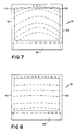
- the processing liquid 96 emerges therefrom as a wave whose front is controlled by the specific shape of the protuberance 100.
- the intermediate portion 104 of the protuberance 100 retards the adjacent portion of the wave front of the processing liquid 96 while the upwardly tapering or sloping lateral ends 106 and 108 gradually offer less and less resistance to the adjacent portions of the wave front.
- the net effect of the protuberance 100 on the wave front is to straighten out its normally tongue shape configuration, as shown in Fig. 7 where opposite end corners 174 and 176 of the film unit may receive too little or none of the processing liquid, to one where the wave front is generally perpendicular to the direction of movement of the film unit 74 thereby providing a more uniform distribution of the processing liquid 96.
- protuberance 100 has been shown as a unitary member having a specific configuration, it could be comprised of a plurality of separate smaller members whose configurations and spacial relation to each other would be a function of the specific control to be applied to the wave front of the processing liquid.
Landscapes
- Physics & Mathematics (AREA)
- General Physics & Mathematics (AREA)
- Cameras Adapted For Combination With Other Photographic Or Optical Apparatuses (AREA)
- Photographic Developing Apparatuses (AREA)
Claims (12)
- Photographischer Apparat der Selbstentwicklerbauart zur Benutzung in Verbindung mit einer Filmkassette (72), die eine Kammer besitzt, welche durch eine Vorderwand (76) und eine Rückwand (88) und zwei diese Wände verbindende Seitenwände (80 und 82) sowie eine vordere Stirnwand (84) und eine hintere Stirnwand (86) definiert ist, wobei die Vorderwand (76) eine Belichtungsöffnung (78) und die vordere Stirnwand (84) einen Filmvorschubschlitz (92) aufweist; wobei mehrere Filmeinheiten (74) in der Kammer gestapelt angeordnet sind, und die vorderste Filmeinheit im Stapel gegen die Belichtungsöffnung (78) gedrückt wird und auf den Vorschubschlitz (92) mit ihrem Vorderrand ausgerichtet ist, und wobei jede der Filmeinheiten (74) einen Behälter (94) mit Behandlungsflüssigkeit (96) am Vorlaufrand aufweist und ein Vorsprung (100) von der Bodenwand der Kassette (72) nach unten vorsteht und sich von der vorderen Stirnwand (84) nach hinten und unten abgeschrägt erstreckt, wobei der Apparat folgende Merkmale aufweist:- eine Filmkammer (60) zur Aufnahme der Filmkassette (72) in Bereitschaftsstellung zur Durchführung aufeinander-folgender Belichtungen der Filmeinheiten (74);- erste Filmfördermittel (144), um die oberste Filmeinheit nach ihrer Belichtung in einer ersten Richtung aus der Filmkassette (72) nach außen vorzuschieben;- zweite Filmfördermittel (148, 150; 154; 158, 160), um die Bewegung der obersten Filmeinheit in der ersten Richtung fortzusetzen und sie dann in einer zweiten Richtung weiterzuführen, die der ersten Richtung im wesentlichen entgegengesetzt ist;- erste druckausübende Organe (114, 116), die im Bewegungspfad der in der zweiten Richtung vorgeschobenen obersten Filmeinheit liegen und die Behandlungsflüssigkeit (96) als Schicht in der obersten Filmeinheit ausbreiten, um die Erzeugung eines sichtbaren Bildes innerhalb der obersten Filmeinheit einzuleiten;- eine sich seitlich erstreckende Druckplatte (118), die innerhalb des Apparates gelagert ist;- der Träger für die Filmkassette stützt die Kassette in einer solchen Lage innerhalb des photographischen Apparates ab, daß ein Spalt zwischen dem Vorsprung (100) der Kassette (72) und der Platte (118) des Apparates derart gebildet wird, daß zweite druckausübende Organe (104, 106, 108; 118) in der zweiten Richtung des Bewegungspfades stromauf der ersten druckausübenden Organe (114, 116) gebildet werden, um die Flüssigkeitsverteilung zu steuern;- der photographische Apparat weist Vorspannmittel auf, um die Druckplatte (118) nach dem Vorsprung (100) der eingesetzten Kassette hin vorzuspannen;- die ersten druckausübenden Organe (114, 116) liegen im Bewegungspfad der Filmeinheit auf der stromabwärtigen Seite des Spaltes der zweiten druckausübenden Organe;- die zweiten druckausübenden Organe sind derart gelagert, daß im Betrieb die Platte (118) auf eine Hauptoberfläche der obersten Filmeinheit einwirkt, während die Behandlungsflüssigkeit (96) ausgebreitet wird, und daß die der Platte (118) gegenüberliegende Oberfläche in Eingriff mit einer Behandlungsflüssigkeits-Ausbreitungs-Steueroberfläche (104, 106, 108) des Vorsprungs derart erfaßt wird, daß die Verteilung der Behandlungsflüssigkeit gesteuert wird, die durch die ersten druckausübenden Organe (114, 116) ausgebreitet wird.
- Photographischer Apparat nach Anspruch 1, bei welchem die ersten druckausübenden Organe aus Quetschwalzen (114, 116) bestehen, die einen Quetschspalt (124) bilden, durch den die oberste Filmeinheit bewegt wird, wobei der photographische Apparat außerdem einen gemeinsamen Träger (112) für die Quetschwalzen (114, 116) aufweist, der schwenkbar durch eine Stange (126) des photographischen Apparates gelagert ist.
- Photographischer Apparat nach Anspruch 2, bei welchem die Filmkassette außerdem einen Ansatz (110) an einer Seitenwand (80) aufweist, und der Träger (112) an diesen Ansatz (110) anstößt, um den Quetschspalt (124) der Quetschwalzen (114, 116) relativ zu dem Bewegungspfad der obersten Filmeinheit in der zweiten Richtung einzustellen.
- Photographischer Apparat nach Anspruch 3, bei welchem der Träger (112) drehbar die druckausübende Platte (118) zur Bewegung nach der Oberfläche (104, 106, 108) und von dieser weg lagert.
- Photographischer Apparat nach Anspruch 4, bei welchem die Druckplatte (118) zwischen zwei Armen (132, 134) verläuft, die schwenkbar auf der Stange (126) gelagert sind.
- Photographischer Apparat nach Anspruch 1, welcher außerdem eine Feder (138) aufweist, um die Platte (118) der zweiten druckausübenden Organe nach der Ausbreitungssteueroberfläche (104, 106, 108) für die Behandlungsflüssigkeit vorzuspannen.
- Photographischer Apparat nach Anspruch 6, welcher außerdem Mittel (142) aufweist, um die Kraft der Feder (142) anzustellen.
- Photographischer Apparat nach Anspruch 7, bei welchem die Einstellmittel einen Nocken (142) aufweisen.
- Photographische Filmkassette (72) zur Benutzung in Verbindung mit einer Kamera der Selbstentwicklerbauart, die erste druckausübende Organe (114, 116) aufweist, die einen Quetschspalt (124) bilden, um eine Behandlungsflüssigkeit über einer Schicht einer belichteten Filmeinheit auszubreiten und die Erzeugung eines sichtbaren Bildes darin einzuleiten, wobei erste und zweite Filmfördermittel vorgesehen sind, um die Filmeinheit in einer ersten und einer zweiten, hierzu entgegengesetzt verlaufenden Richtung zu bewegen, wobei die Bewegung in der zweiten Richtung in einem Pfad unter der Bodenwand der Kassette erfolgt; wobei die Kassette (72) ein erstes Teil (100) einer zweiten druckausübenden Einrichtung aufweist, um gleichzeitig die belichtete Filmeinheit in Eingriff mit einer weiteren Oberfläche zu bringen, wobei die Filmkassette (72) folgende Merkmale umfaßt:- eine Kammer wird durch eine Vorderwand (76), eine Rückwand (88), zwei im seitlichen Abstand angeordnete Seitenwände (80, 82), eine vordere Stirnwand (84) und eine hintere Stirnwand (86) gebildet, wobei die Vorderwand (76) eine Belichtungsöffnung (78) aufweist, und die vordere Stirnwand (84) eine Austrittsöffnung (92) aufweist, durch die eine Filmeinheit aus der Kammer herausbewegt werden kann;- mehrere Filmeinheiten (74) sind in der Kammer gestapelt, wobei die oberste Filmeinheit des Stapels an die Belichtungsöffnung gedrückt wird, wobei der Vorlaufrand der obersten Filmeinheit in einer Lage befindlich ist, in der die Filmeinheit durch die Austrittsöffnung bewegt werden kann und jede der Filmeinheiten einen Vorrat an Behandlungsflüssigkeit enthält , und jede Filmeinheit aus der Filmkassette über die Austrittsöffnung und längs eines Bewegungspfades im photographischen Apparat nach der Belichtung bewegt wird, wobei die Bewegung einen Durchtritt durch den Quetschspalt (124) einschießt;wobei das erste Teil (100) der zweiten druckausübenden Organe von einer Ausbreitungssteueroberfläche (104, 106, 108) für die Behandlungsflüssigkeit definiert ist, die sich von der Bodenwand der Kassette erstreckt, und wobei die Ausbreitungssteueroberfläche für die Behandlungsflüssigkeit mit einem zweiten Teil (118) der zweiten druckausübenden Organe zusammenwirkt, das von dem photographischen Apparat definiert ist, um die Ausbreitung der Behandlungsflüssigkeit durch die ersten druckausübenden Organe (114, 116) zu steuern.
- Photographische Filmkassette nach Anspruch 9, bei welcher die Ausbreitungssteueroberfläche für die Behandlungsflüssigkeit einstückig in einer äußeren Oberfläche der Bodenwand ausgebildet ist.
- Photographische Filmkassette nach Anspruch 9, bei welcher die Filmkassette außerdem einen Ansatz (110) aufweist, der von einer äußeren Oberfläche (80) der Kassette vorsteht und auf die ersten druckausübenden Organe des photographischen Apparates einwirkt, um die Lage des Quetschspaltes (124) relativ zum Bewegungspfad einer Filmeinheit nach deren photographischer Belichtung einzustellen.
- Photographische Filmkassette nach Anspruch 11, bei welcher der Ansatz (110) integral an einer (80) der Seitenwände ausgebildet ist.
Applications Claiming Priority (2)
| Application Number | Priority Date | Filing Date | Title |
|---|---|---|---|
| US07/188,970 US4839676A (en) | 1988-05-02 | 1988-05-02 | Film cassette-liquid spread roller assembly interface |
| US188970 | 1994-01-28 |
Publications (2)
| Publication Number | Publication Date |
|---|---|
| EP0340682A1 EP0340682A1 (de) | 1989-11-08 |
| EP0340682B1 true EP0340682B1 (de) | 1994-05-25 |
Family
ID=22695336
Family Applications (1)
| Application Number | Title | Priority Date | Filing Date |
|---|---|---|---|
| EP89107805A Expired - Lifetime EP0340682B1 (de) | 1988-05-02 | 1989-04-28 | Photografische Kamera und Filmkassette mit einer Verteilervorrichtung für eine Flüssigkeit |
Country Status (5)
| Country | Link |
|---|---|
| US (1) | US4839676A (de) |
| EP (1) | EP0340682B1 (de) |
| JP (1) | JP2725833B2 (de) |
| CA (1) | CA1305623C (de) |
| DE (1) | DE68915475T2 (de) |
Families Citing this family (9)
| Publication number | Priority date | Publication date | Assignee | Title |
|---|---|---|---|---|
| JPH02287527A (ja) * | 1989-04-28 | 1990-11-27 | Fuji Photo Film Co Ltd | ビデオプリンタ |
| US5019842A (en) * | 1989-12-29 | 1991-05-28 | Polaroid Corporation | Extendable shade in instant camera for protecting film unit from ambient light |
| US5049907A (en) * | 1990-11-08 | 1991-09-17 | Polaroid Corporation | Camera having chamber for storing exposed film units during their development |
| US5619292A (en) * | 1994-05-24 | 1997-04-08 | Olympus Optical Co., Ltd. | Camera |
| EP1065558B1 (de) * | 1999-07-02 | 2008-02-27 | FUJIFILM Corporation | Verfahren und Gerät zur Herstellung von Sofortfilmeinheit |
| US6330397B1 (en) | 2000-01-31 | 2001-12-11 | Polaroid Corporation | Film unit drive assembly for an electronic photographic printer and camera and related method thereof |
| US6417911B1 (en) | 2000-01-31 | 2002-07-09 | Polaroid Corporation | Processing fluid spread system for an electronic photographic printer and camera and related method thereof |
| US6795114B1 (en) | 2000-01-31 | 2004-09-21 | Polaroid Corporation | Film unit drive assembly for a detachable electronic photographic printer and camera |
| US6317561B1 (en) | 2000-01-31 | 2001-11-13 | Polaroid Corporation | Processing fluid spread system for a detachable electronic photographic printer and camera |
Family Cites Families (13)
| Publication number | Priority date | Publication date | Assignee | Title |
|---|---|---|---|---|
| US3460452A (en) * | 1967-09-18 | 1969-08-12 | Polaroid Corp | Self-developing camera and process performed therein |
| US3421468A (en) * | 1968-04-16 | 1969-01-14 | Bobby G Newsom | Hydrofoil craft |
| US3722383A (en) * | 1970-06-30 | 1973-03-27 | Polaroid Corp | Unique waste-free camera system of the self-developing type |
| US3779770A (en) * | 1972-04-24 | 1973-12-18 | Polaroid Corp | A photographic film assemblage for a diffusion transfer film |
| US3810211A (en) * | 1972-04-24 | 1974-05-07 | Polaroid Corp | Self-developing camera system |
| US3777647A (en) * | 1972-05-23 | 1973-12-11 | Polaroid Corp | Photographic apparatus and method for treating photographic materials with a liquid |
| US3832731A (en) * | 1973-04-26 | 1974-08-27 | Polaroid Corp | Photographic film assemblage |
| US4104669A (en) * | 1977-04-15 | 1978-08-01 | Polaroid Corporation | Thermally responsive photographic processing apparatus for use with self-processable film units |
| US4226519A (en) * | 1979-04-02 | 1980-10-07 | Polaroid Corporation | Self-developing film pack with improved spread control structure |
| US4545663A (en) * | 1982-12-27 | 1985-10-08 | Polaroid Corporation | Integral self-developing film unit and system for use thereof |
| US4693963A (en) * | 1986-04-01 | 1987-09-15 | Polaroid Corporation | Self-developing integral film unit |
| US4664497A (en) * | 1986-07-02 | 1987-05-12 | Polaroid Corporation | Camera having chamber for storing exposed film units during their development |
| US4688912A (en) * | 1986-11-20 | 1987-08-25 | Polaroid Corporation | Photographic apparatus having a film advancing and processing assembly |
-
1988
- 1988-05-02 US US07/188,970 patent/US4839676A/en not_active Expired - Lifetime
-
1989
- 1989-04-12 CA CA000596418A patent/CA1305623C/en not_active Expired - Fee Related
- 1989-04-27 JP JP1106134A patent/JP2725833B2/ja not_active Expired - Lifetime
- 1989-04-28 EP EP89107805A patent/EP0340682B1/de not_active Expired - Lifetime
- 1989-04-28 DE DE68915475T patent/DE68915475T2/de not_active Expired - Fee Related
Non-Patent Citations (1)
| Title |
|---|
| RESEARCH DISCLOSURE, no. 191, March 1980, pp. 107,108, London, GB ; H. ETTISCHER : "Film unit deflecting means for instant picture camera". * |
Also Published As
| Publication number | Publication date |
|---|---|
| JP2725833B2 (ja) | 1998-03-11 |
| EP0340682A1 (de) | 1989-11-08 |
| US4839676A (en) | 1989-06-13 |
| CA1305623C (en) | 1992-07-28 |
| DE68915475D1 (de) | 1994-06-30 |
| JPH02146029A (ja) | 1990-06-05 |
| DE68915475T2 (de) | 1994-09-08 |
Similar Documents
| Publication | Publication Date | Title |
|---|---|---|
| US3948662A (en) | Method of processing film unit with processing solution wave front modifying means | |
| US4723140A (en) | Compact folding camera construction | |
| EP0340682B1 (de) | Photografische Kamera und Filmkassette mit einer Verteilervorrichtung für eine Flüssigkeit | |
| US4389110A (en) | Folding camera | |
| US4226519A (en) | Self-developing film pack with improved spread control structure | |
| US3537370A (en) | Camera structure | |
| US3405619A (en) | Camera and film useful therein | |
| US4392732A (en) | Folding camera with viewfinder having independently mounted optical elements | |
| US4387978A (en) | Folding camera with pivotally mounted viewfinder | |
| US4064518A (en) | Compact self-developing camera with folded optical image path | |
| US4104669A (en) | Thermally responsive photographic processing apparatus for use with self-processable film units | |
| US4174164A (en) | Photographic processing apparatus | |
| EP0487508B1 (de) | Photographische Kamera | |
| US4087831A (en) | Bearing block mount for a photographic fluid spreading apparatus | |
| US3994002A (en) | Self-developing camera with film unit deflecting structure | |
| EP0268132B1 (de) | Photographisches Gerät mit Filmförder- und Behandlungsvorrichtung | |
| JPS607772B2 (ja) | 写真装置 | |
| US3820137A (en) | Photographic apparatus | |
| US3460452A (en) | Self-developing camera and process performed therein | |
| US3270643A (en) | Photographic apparatus | |
| US4395102A (en) | Bellows for folding camera | |
| US4755839A (en) | Pivotally mounted spread roller assembly | |
| US5946502A (en) | Photographic apparatus | |
| US3952835A (en) | Flat torque rate drive system | |
| CA2047832A1 (en) | Camera having chamber for storing exposed film units during their development |
Legal Events
| Date | Code | Title | Description |
|---|---|---|---|
| PUAI | Public reference made under article 153(3) epc to a published international application that has entered the european phase |
Free format text: ORIGINAL CODE: 0009012 |
|
| AK | Designated contracting states |
Kind code of ref document: A1 Designated state(s): DE FR GB |
|
| 17P | Request for examination filed |
Effective date: 19900425 |
|
| 17Q | First examination report despatched |
Effective date: 19920602 |
|
| GRAA | (expected) grant |
Free format text: ORIGINAL CODE: 0009210 |
|
| AK | Designated contracting states |
Kind code of ref document: B1 Designated state(s): DE FR GB |
|
| ET | Fr: translation filed | ||
| REF | Corresponds to: |
Ref document number: 68915475 Country of ref document: DE Date of ref document: 19940630 |
|
| PLBE | No opposition filed within time limit |
Free format text: ORIGINAL CODE: 0009261 |
|
| STAA | Information on the status of an ep patent application or granted ep patent |
Free format text: STATUS: NO OPPOSITION FILED WITHIN TIME LIMIT |
|
| 26N | No opposition filed | ||
| PGFP | Annual fee paid to national office [announced via postgrant information from national office to epo] |
Ref country code: FR Payment date: 20000313 Year of fee payment: 12 |
|
| PGFP | Annual fee paid to national office [announced via postgrant information from national office to epo] |
Ref country code: GB Payment date: 20000321 Year of fee payment: 12 |
|
| PGFP | Annual fee paid to national office [announced via postgrant information from national office to epo] |
Ref country code: DE Payment date: 20000324 Year of fee payment: 12 |
|
| PG25 | Lapsed in a contracting state [announced via postgrant information from national office to epo] |
Ref country code: GB Free format text: LAPSE BECAUSE OF NON-PAYMENT OF DUE FEES Effective date: 20010428 |
|
| PG25 | Lapsed in a contracting state [announced via postgrant information from national office to epo] |
Ref country code: FR Free format text: THE PATENT HAS BEEN ANNULLED BY A DECISION OF A NATIONAL AUTHORITY Effective date: 20010430 |
|
| GBPC | Gb: european patent ceased through non-payment of renewal fee |
Effective date: 20010428 |
|
| PG25 | Lapsed in a contracting state [announced via postgrant information from national office to epo] |
Ref country code: DE Free format text: LAPSE BECAUSE OF NON-PAYMENT OF DUE FEES Effective date: 20020201 |
|
| REG | Reference to a national code |
Ref country code: FR Ref legal event code: ST |