EP0340437A2 - Appareil et méthode pour mesurer des réflexions sombres et brillantes d'un matériau en feuilles - Google Patents
Appareil et méthode pour mesurer des réflexions sombres et brillantes d'un matériau en feuilles Download PDFInfo
- Publication number
- EP0340437A2 EP0340437A2 EP89105033A EP89105033A EP0340437A2 EP 0340437 A2 EP0340437 A2 EP 0340437A2 EP 89105033 A EP89105033 A EP 89105033A EP 89105033 A EP89105033 A EP 89105033A EP 0340437 A2 EP0340437 A2 EP 0340437A2
- Authority
- EP
- European Patent Office
- Prior art keywords
- radiation
- bright
- liquid crystal
- dark
- optical
- Prior art date
- Legal status (The legal status is an assumption and is not a legal conclusion. Google has not performed a legal analysis and makes no representation as to the accuracy of the status listed.)
- Withdrawn
Links
Images


Classifications
-
- G—PHYSICS
- G01—MEASURING; TESTING
- G01N—INVESTIGATING OR ANALYSING MATERIALS BY DETERMINING THEIR CHEMICAL OR PHYSICAL PROPERTIES
- G01N21/00—Investigating or analysing materials by the use of optical means, i.e. using sub-millimetre waves, infrared, visible or ultraviolet light
- G01N21/17—Systems in which incident light is modified in accordance with the properties of the material investigated
- G01N21/47—Scattering, i.e. diffuse reflection
- G01N21/4738—Diffuse reflection, e.g. also for testing fluids, fibrous materials
- G01N2021/4764—Special kinds of physical applications
- G01N2021/4773—Partly or totally translucent samples
-
- G—PHYSICS
- G01—MEASURING; TESTING
- G01N—INVESTIGATING OR ANALYSING MATERIALS BY DETERMINING THEIR CHEMICAL OR PHYSICAL PROPERTIES
- G01N21/00—Investigating or analysing materials by the use of optical means, i.e. using sub-millimetre waves, infrared, visible or ultraviolet light
- G01N21/84—Systems specially adapted for particular applications
- G01N21/86—Investigating moving sheets
- G01N2021/8663—Paper, e.g. gloss, moisture content
-
- G—PHYSICS
- G01—MEASURING; TESTING
- G01N—INVESTIGATING OR ANALYSING MATERIALS BY DETERMINING THEIR CHEMICAL OR PHYSICAL PROPERTIES
- G01N2201/00—Features of devices classified in G01N21/00
- G01N2201/06—Illumination; Optics
- G01N2201/067—Electro-optic, magneto-optic, acousto-optic elements
-
- G—PHYSICS
- G01—MEASURING; TESTING
- G01N—INVESTIGATING OR ANALYSING MATERIALS BY DETERMINING THEIR CHEMICAL OR PHYSICAL PROPERTIES
- G01N2201/00—Features of devices classified in G01N21/00
- G01N2201/08—Optical fibres; light guides
- G01N2201/0833—Fibre array at detector, resolving
-
- G—PHYSICS
- G01—MEASURING; TESTING
- G01N—INVESTIGATING OR ANALYSING MATERIALS BY DETERMINING THEIR CHEMICAL OR PHYSICAL PROPERTIES
- G01N2201/00—Features of devices classified in G01N21/00
- G01N2201/12—Circuits of general importance; Signal processing
- G01N2201/128—Alternating sample and standard or reference part in one path
Definitions
- the present invention relates generally to process automation for systems which manufacture sheet materials, and more particularly to apparatus and methods for on-line measurement of various quality attributes of such materials, wherein measurement is based on reflectance.
- this invention pertains to apparatus and methods for use in providing measurements of quality attributes wherein the measurements require that two separate determinations of reflectance be made as the sheet material is alternately positioned against dark and light backgrounds.
- the reflectance may be indicative of a variety of quality attributes including gloss, smoothness, opacity, and color to mention a few.
- the color of the material can be ascertained by illuminating the material with white light and measuring the reflectance therefrom for each of a plurality of wavelength bands in the visible region of the electromagnetic spectrum. Such measurements can be accomplished by using a spectrophotometer such as that disclosed in U.S. Patent No. 4,076,421 Kishner, for example.
- a spectrophotometer such as that disclosed in U.S. Patent No. 4,076,421 Kishner, for example.
- the manufacturer is concerned with the color of the material as it appears to a consumer who observes the material in the form of a wound-up roll or a stack of individual layers as in a book or a napkin.
- a spectrophotometer or other instrument remains in one location on one side of the moving sheet material while a mechanical device shuttles the dark and light backgrounds successively into the radiation path and against the other side of the sheet so that sequential measurements are made. This arrangement is undesirable for a number of reasons including differential dust buildup on the dark and light backgrounds, and the need to manufacture and maintain cumbersome mechanical devices.
- the present invention provides apparatus and methods for measuring dark and bright reflectances for translucent sheet material in accordance with the above-stated need.
- the apparatus comprises first optical means for illuminating one side of the sheet material with a source of optical electromagnetic radiation of substantially uniform intensity so that a portion of the radiation is transmitted through the sheet material and another portion of the radiation is reflected by the sheet material.
- the apparatus also comprises optical gating means positioned adjacent the other side of the sheet material in fixed position relative to the source.
- the optical gating means absorbs substantially all of the transmitted portion of the radiation when switched to a dark state and reflects substantially all of the transmitted portion of the radiation back into the sheet material when switched to a bright state.
- the apparatus further comprises second optical means for collecting the reflected portion of the radiation and the portion of the transmitted portion of the radiation reflected by the optical gate means and retransmitted through the sheet material to provide a total reflectance.
- the total reflectance has a dark reflectance intensity when the optical gate means is in the dark state and a bright reflectance intensity when the optical gate means is in the bright state.
- the apparatus also comprises sensing means, responsive to the radiation collected by the second optical means, for providing a dark signal having a magnitude corresponding to the dark reflectance intensity and a bright signal having a magnitude corresponding to the bright reflectance intensity.
- the dark and bright signals can be used to compute the reflective opacity of the sheet material.
- the apparatus can also be used so that the first optical means directly illuminates the optical gating means when switched to the bright state so that a portion of the radiation is reflected by the optical gating means.
- the second optical means collects the portion reflected by optical gating means to provide a reference reflectance and the sensing means provides a reference signal having a magnitude corresponding to the intensity of the reference reflectance.
- a standardized reflective opacity of the sheet material can be computed from the bright and dark signals and the reference signal.
- the optical gating means comprises a liquid crystal device and a backing plate.
- the liquid crystal is positioned between the sheet material and the backing plate and has an input for connecting and disconnecting a voltage source to switch the liquid crystal between the dark and bright states.
- the liquid crystal is a field-effect liquid crystal and the backing plate has a reflective surface facing the liquid crystal.
- the liquid crystal absorbs the transmitted portion of the source in the dark state when the voltage source is connected to the input thereof and the backing plate reflects the transmitted portion of the source in the bright state when the voltage source is disconnected from the input thereof making the liquid crystal transparent.
- the liquid crystal is a dynamic-scattering liquid crystal and the backing plate has an absorptive surface facing the liquid crystal. As a result, the liquid crystal reflects the transmitted portion of the radiation in the bright state when the voltage source is connected to the input thereof and the backing plate absorbs the transmitted portion of the radiation in the dark state when the voltage source is disconnected from the input thereof making the liquid crystal transparent.
- the present invention also meets the stated need by providing a method for measuring the dark and bright reflectances of translucent sheet material.
- the method comprises the steps of illuminating one side of the sheet material with a source of optical electromagnetic radiation of substantially uniform intensity. A portion of the radiation is transmitted through the sheet material and another portion of the radiation is reflected by the sheet material.
- the method also comprises the step of positioning an optical gate adjacent the other side of the sheet material in a fixed position relative to the source. The optical gate absorbs substantially all of the transmitted portion of the radiation when the optical gate is switched to a dark state and reflects substantially all of the transmitted portion of the radiation back through the sheet material when the optical gate is switched to a bright state.
- the method further comprises the step of collecting the reflected portion of the radiation and the portion of the transmitted portion of the radiation reflected by the optical gate and retransmitted through the sheet to provide a total reflectance.
- the total reflectance has a dark reflectance intensity when the optical gate is in the dark state and a bright reflectance intensity when the optical gate is in the bright state.
- the method also comprises the step of providing a dark signal having a magnitude corresponding to the dark reflectance intensity and a bright signal having a magnitude corresponding to the bright reflectance intensity.
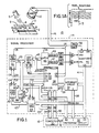
- An apparatus for measuring dark and bright reflectances of translucent sheet material 2 is indicated generally at 10 in Fig. 1 and comprises first optical means, optical gating means, second optical means and sensing means.
- the first optical means comprises a source 12 which provides optical electromagnetic radiation of substantially uniform intensity through a diffusing screen 13 and an optical system 14 which includes a cylindrical reflector 16 and a pair of annular baffles 18 supported on a cylindrical frame 20 between two glass annuli 22 and an annular baffle 24 supported on a central housing 26. Central housing 26 is axially supported within cylindrical frame 20 between glass annuli 22.
- source 12 provides a source of monochromatic radiation or light to measure the opacity at one wavelength.
- signal processor 50 might be used to amplify the signals or to convert the signals to digital signals for subsequent processing.
- the signal processor forms no part of the present invention.
- a reference photodetector 52 is located adjacent source 12 in order to monitor the intensity of the radiation. The signal produced by photodetector 52 is also provided to signal processor 50 to properly bias the dark and bright signals provided by photodetector 48.
- source 12 provides visible white light and is preferably a pulsed xenon flashtube.
- the xenon flashtube can provide a short, intense pulse of broad spectrum illumination.
- the second optical means separates the total reflectance R(t) into its component wavelengths, so that there is a dark reflectance intensity R(d) and a bright reflectance intensity R(b) for each component wavelength.
- the second optical means further comprises a lens 54, a filter 55, a collimating lens 56, a dispersive element 57, and a lens 58.
- Fiber optic bundle 44 does not transmit light via bundle 46 to a photodetector, but rather to lens 54 which focuses the light through a pinhole in filter 55 that restricts the angular spread of the light.
- the light passing through the pinhole is collimated by lens 56 onto dispersive element 57, which may be a prism or a diffraction grating as shown in Fig. 1. which is circularly symmetrical, and follow a path defined by annular baffles 18 and 24 and reflector 16.
- Reflector 16 which is preferably a mirror, directs the rays inward toward sheet material 2 at angles of approximately 45 degrees from the normal of sheet material 2.
- the rays from reflector 16 converge toward sheet material 2 and form a circular spot 28 of illumination of uniform intensity on sheet material 2.
- the uniformity of spot 28 is controlled by the degree to which screen 13 diffuses the light.
- a portion of the light rays is transmitted through sheet material 2 and another portion of the light rays is reflected by sheet material 2.
- the portion of light transmitted through sheet material 2 impinges upon optical gating means 30, which is positioned adjacent the other side of sheet material 2 in a fixed position relative to the first optical means or optical system 14.
- Optical gating means 30 comprises a liquid crystal 32 and a backing plate 34.
- Liquid crystal 32 is positioned between sheet material 2 and backing plate 34 and has an input 36 for connecting and disconnecting a voltage source (not shown) to switch liquid crystal 32 between a dark state and a bright state.
- Optical gate means 30 absorbs substantially all of the transmitted portion of the light when switched to the dark state and reflects substantially all of the transmitted portion of the light back through sheet material 2 when switched to the bright state. This will be discussed below in more detail.
- Apparatus 10 also comprises second optical means for collecting the portion of light reflected by sheet material 2, and the portion of the light transmitted through sheet material 2 that is reflected by optical gate means 30 and retransmitted through the sheet material, to provide a total reflectance R(t).
- the total reflectance has a dark reflectance intensity R(d) when optical gate means 30 is in the dark state and a bright reflectance intensity R(b) when optical gate means 30 is in the bright state.
- the second optical means comprises a lens 42 and a fiber optics bundle 44, both of which are mounted in central housing 26. Lens 42 collects the light (R(t)) and focuses it onto fiber optics bundle 44 which transmits the light as indicated by dashed line 46 to a photodetector 48.
- the single photodetector 48 constitutes the sensing means.
- the sensing means is responsive to the second optical means and provides a dark signal having a magnitude corresponding to the dark reflectance intensity and a bright signal having a magnitude corresponding to the bright reflectance intensity.
- the dark and bright signals produced by photodetector 48 are provided to a signal processor 50 which processes the signals in a manner that depends upon the specific application.
- Grating 57 separates the incident white light into its component wavelengths by a unique angle.
- the red light rays follow a path defined within dashed lines R and the violet rays follow a path defined within dashed lines V.
- Lens 58 focuses the separated light onto a linear array 60 of discrete photodetectors, similar to photodetector 48, so that the light in the red path is focused at point 60(r) on one of the photodetectors and the light in the violet path is focused at point 60(v) on another photodetector at the other end of array 60.
- the light at all intermediate wavelengths is focused at different points along array 60 between points 60(r) and 60(v).
- Each photodetector measures only a narrow band of wavelengths.
- each band depends upon the diameter of the pinhole and the width of the corresponding photodetector.
- the sensing means comprises the array 60 of photodetectors and provides a dark signal and a bright signal for each component wavelength of light measured by a photodetector in array 60. This embodiment is described in more detail in U.S. Patent No. 4,076,421, the disclosure of which is incorporated herein by reference.
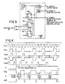
- liquid crystal 32 is a field-effect liquid crystal and backing plate 34 has a reflective surface facing the liquid crystal.
- a field-effect liquid crystal 72 comprises a liquid crystal envelope 73 between transparent electrodes 74 and front and back filters 75 and 76. Front and back filters 75 and 76 are polarized in directions orthogonal to each other. Electrodes 74 are connected to a voltage source 77 via a switch 78 which is opened and closed by a signal provided by signal processor 50 along wire 36. When no field is applied by voltage source 77 as shown in Fig.
- liquid crystal 72 is transparent so that the reflective surface of backing plate 34 reflects the transmitted portion of the source radiation, rays A , B and C , in the bright state. However, when a field is applied by voltage source 77 as shown in Fig. 4, liquid crystal 72 absorbs the transmitted portion of the source radiation in the dark state.
- liquid crystal 32 is a dynamic-scattering liquid crystal and backing plate 34 has an absorptive surface facing the liquid crystal.
- a dynamic-scattering liquid crystal 82 comprises a liquid crystal envelope 83 between transparent electrodes 84 and front and back glass plates 85 and 86. Electrodes 84 are connected to a voltage source 87 via a switch 88 which is opened and closed by a signal provided by signal processor 50 along wire 36.
- voltage source 87 When a field is applied by voltage source 87 as shown in Fig. 5, liquid crystal 82 becomes opaque and frosty so that it reflects the transmitted portion of source 12, rays A(t), B(t) and C(t), in the bright state.
- liquid crystal 82 becomes transparent so that the surface of backing plate 34 absorbs the transmitted portion of source radiation in the dark state.
- the monochromatic embodiment is used to provide the dark and bright signals, V(d) and V(b), respectively, as described above so that the reflective opacity of sheet material 2 can be computed.
- the monochromatic embodiment of apparatus 10 is first used to provide a reference signal V(r) necessary for such computation. This is accomplished by using source 12 to directly illuminate (i.e. in the absence of the sheet material 2) optical gating means 30 when switched to the bright state. A portion of source 12 is reflected by optical gating means 30 and the second optical means collects the portion reflected by optical gating means 30 to provide a reference reflectance.
- the sensing means, photodetector 38 provides the reference signal V(r) which has a magnitude corresponding to the intensity of the reference reflectance.
- the polychromatic embodiment is used in a similar fashion to provide the same signals but for each component wavelength as described above so that the reflectance of the sheet material 2 can be computed for each component wavelength using the above equation. From the resulting plurality of reflectance measurements the color of the sheet material 2 can be computed by known formulae.
Landscapes
- Physics & Mathematics (AREA)
- Health & Medical Sciences (AREA)
- Life Sciences & Earth Sciences (AREA)
- Chemical & Material Sciences (AREA)
- Analytical Chemistry (AREA)
- Biochemistry (AREA)
- General Health & Medical Sciences (AREA)
- General Physics & Mathematics (AREA)
- Immunology (AREA)
- Pathology (AREA)
- Investigating Or Analysing Materials By Optical Means (AREA)
Applications Claiming Priority (2)
| Application Number | Priority Date | Filing Date | Title |
|---|---|---|---|
| US07/187,204 US4944594A (en) | 1988-04-28 | 1988-04-28 | Apparatus and method for measuring dark and bright reflectances of sheet material |
| US187204 | 2002-06-27 |
Publications (2)
| Publication Number | Publication Date |
|---|---|
| EP0340437A2 true EP0340437A2 (fr) | 1989-11-08 |
| EP0340437A3 EP0340437A3 (fr) | 1991-03-20 |
Family
ID=22688012
Family Applications (1)
| Application Number | Title | Priority Date | Filing Date |
|---|---|---|---|
| EP19890105033 Withdrawn EP0340437A3 (fr) | 1988-04-28 | 1989-03-21 | Appareil et méthode pour mesurer des réflexions sombres et brillantes d'un matériau en feuilles |
Country Status (4)
| Country | Link |
|---|---|
| US (1) | US4944594A (fr) |
| EP (1) | EP0340437A3 (fr) |
| CA (1) | CA1315124C (fr) |
| FI (1) | FI892024A (fr) |
Families Citing this family (13)
| Publication number | Priority date | Publication date | Assignee | Title |
|---|---|---|---|---|
| US5094695A (en) * | 1990-12-03 | 1992-03-10 | The Babcock & Wilcox Company | Furnace cleanliness monitor for high reflectivity ash |
| US5642189A (en) * | 1995-06-12 | 1997-06-24 | Measurex Corporation | Color sensor simulating standard source illuminant |
| DE19633557A1 (de) * | 1996-08-21 | 1998-03-05 | Techkon Elektronik Gmbh | Spektrales Handmeßgerät |
| US6198536B1 (en) | 1998-09-01 | 2001-03-06 | X-Rite, Incorporated | Portable scanning spectrophotometer |
| CA2279928A1 (fr) * | 1998-09-01 | 2000-03-01 | X-Rite, Incorporated | Spectrophotometre portatif a balayage |
| US6332573B1 (en) | 1998-11-10 | 2001-12-25 | Ncr Corporation | Produce data collector and produce recognition system |
| US6155489A (en) * | 1998-11-10 | 2000-12-05 | Ncr Corporation | Item checkout device including a bar code data collector and a produce data collector |
| US6285452B1 (en) | 2000-11-01 | 2001-09-04 | X-Rite Incorporated | Portable scanning spectrophotometer |
| US6431446B1 (en) | 1999-07-28 | 2002-08-13 | Ncr Corporation | Produce recognition system and method |
| FI20001970A (fi) * | 2000-09-06 | 2002-04-15 | Metso Paper Automation Oy | Paperin tai kartongin mittaus |
| FI118828B (fi) * | 2004-12-31 | 2008-03-31 | Metso Automation Oy | Menetelmä ja laitteisto liikkuvan rainan värin mittaamiseksi |
| US7573575B2 (en) | 2005-12-29 | 2009-08-11 | Honeywell International Inc. | System and method for color measurements or other spectral measurements of a material |
| US7688447B2 (en) | 2005-12-29 | 2010-03-30 | Honeywell International Inc. | Color sensor |
Citations (6)
| Publication number | Priority date | Publication date | Assignee | Title |
|---|---|---|---|---|
| US3455637A (en) * | 1964-08-07 | 1969-07-15 | Giannini Controls Corp | Method and apparatus for measuring the opacity of sheet material |
| US3476482A (en) * | 1967-09-27 | 1969-11-04 | Conrac Corp | Opacimeter for comparing light from different areas of sample sheet |
| US4076421A (en) * | 1976-03-23 | 1978-02-28 | Kollmorgen Technologies Corporation | Spectrophotometer with parallel sensing |
| US4364639A (en) * | 1980-08-25 | 1982-12-21 | Northern Telecom Limited | Variable attenuation electro-optic device |
| EP0181155A2 (fr) * | 1984-11-06 | 1986-05-14 | Measurex Corporation | Système pour mesurer la couleur d'une matière |
| US4678325A (en) * | 1983-05-05 | 1987-07-07 | Olavi Lehtikoski | Apparatus for measuring optical properties of paper |
Family Cites Families (6)
| Publication number | Priority date | Publication date | Assignee | Title |
|---|---|---|---|---|
| US1950975A (en) * | 1932-11-19 | 1934-03-13 | Paper Patents Co | Opacimeter and method of measuring opacity |
| US3936189A (en) * | 1974-03-13 | 1976-02-03 | Sentrol Systems Ltd. | On-line system for monitoring the color, opacity and brightness of a moving web |
| US4224513A (en) * | 1978-04-06 | 1980-09-23 | Measurex Corporation | Apparatus for the on-line measurement of the opacity of a paper sheet |
| US4624572A (en) * | 1982-02-05 | 1986-11-25 | Den Bosch Francois J G Van | Non-invasive reflectance spectrophotometric apparatus |
| EP0106636B1 (fr) * | 1982-10-20 | 1989-01-25 | The Secretary of State for Defence in Her Britannic Majesty's Government of the United Kingdom of Great Britain and | Miroir comportant une cellule à cristal liquide |
| US4715715A (en) * | 1984-11-06 | 1987-12-29 | Measurex Corporation | System for measuring the color of a material |
-
1988
- 1988-04-28 US US07/187,204 patent/US4944594A/en not_active Expired - Lifetime
-
1989
- 1989-03-21 EP EP19890105033 patent/EP0340437A3/fr not_active Withdrawn
- 1989-04-19 CA CA000597091A patent/CA1315124C/fr not_active Expired - Fee Related
- 1989-04-27 FI FI892024A patent/FI892024A/fi not_active Application Discontinuation
Patent Citations (6)
| Publication number | Priority date | Publication date | Assignee | Title |
|---|---|---|---|---|
| US3455637A (en) * | 1964-08-07 | 1969-07-15 | Giannini Controls Corp | Method and apparatus for measuring the opacity of sheet material |
| US3476482A (en) * | 1967-09-27 | 1969-11-04 | Conrac Corp | Opacimeter for comparing light from different areas of sample sheet |
| US4076421A (en) * | 1976-03-23 | 1978-02-28 | Kollmorgen Technologies Corporation | Spectrophotometer with parallel sensing |
| US4364639A (en) * | 1980-08-25 | 1982-12-21 | Northern Telecom Limited | Variable attenuation electro-optic device |
| US4678325A (en) * | 1983-05-05 | 1987-07-07 | Olavi Lehtikoski | Apparatus for measuring optical properties of paper |
| EP0181155A2 (fr) * | 1984-11-06 | 1986-05-14 | Measurex Corporation | Système pour mesurer la couleur d'une matière |
Also Published As
| Publication number | Publication date |
|---|---|
| FI892024A0 (fi) | 1989-04-27 |
| US4944594A (en) | 1990-07-31 |
| EP0340437A3 (fr) | 1991-03-20 |
| CA1315124C (fr) | 1993-03-30 |
| FI892024A (fi) | 1989-10-29 |
Similar Documents
| Publication | Publication Date | Title |
|---|---|---|
| US4944594A (en) | Apparatus and method for measuring dark and bright reflectances of sheet material | |
| US5764352A (en) | Process and apparatus for spectral reflectance and transmission measurements | |
| JP3406944B2 (ja) | レンズ測定装置 | |
| KR900018643A (ko) | 삼각형법 광센서 및 그장치 | |
| US4801212A (en) | Optical system for radiation thermometer | |
| US5880845A (en) | Apparatus for measuring the photometric and colorimetrics characteristics of an object | |
| EP0132342B1 (fr) | Procédé et appareil pour le réglage du spectre d'un faisceau lumineux | |
| EP0168960B1 (fr) | Détecteur optique de déplacements | |
| EP0169664B1 (fr) | Dispositif pour la détermination du degré d'oxydation d'une couche oxydée | |
| US4222064A (en) | Optical property measurement system and method | |
| US5933243A (en) | Device for color measuring | |
| KR910001840B1 (ko) | 변위 탐지 | |
| US4937637A (en) | Dual reading head transmission/reflection densitometer | |
| GB2086572A (en) | Differential pressure measuring apparatus | |
| US5084628A (en) | Sheet inspection method and apparatus having retroreflecting means | |
| US4519704A (en) | Measurement of optical refractive index profiles | |
| JPH01188816A (ja) | 分光型走査顕微鏡 | |
| GB2249389A (en) | Densitometers | |
| NL8900070A (nl) | Inrichting voor het inspekteren van een interferentiefilter voor een projektie-televisiebeeldbuis. | |
| CN216051344U (zh) | 多功能便携式玻璃表面应力仪 | |
| US20070195312A1 (en) | Refractometer | |
| JPH05203495A (ja) | 色彩計及び色彩計の測色方法 | |
| JPS617446A (ja) | 線状体表面測定装置 | |
| JP3568631B2 (ja) | 宝石の色鑑定装置 | |
| JPS642888B2 (fr) |
Legal Events
| Date | Code | Title | Description |
|---|---|---|---|
| PUAI | Public reference made under article 153(3) epc to a published international application that has entered the european phase |
Free format text: ORIGINAL CODE: 0009012 |
|
| AK | Designated contracting states |
Kind code of ref document: A2 Designated state(s): DE FR GB IT SE |
|
| RAP1 | Party data changed (applicant data changed or rights of an application transferred) |
Owner name: ABB PROCESS AUTOMATION, INC. |
|
| PUAL | Search report despatched |
Free format text: ORIGINAL CODE: 0009013 |
|
| AK | Designated contracting states |
Kind code of ref document: A3 Designated state(s): DE FR GB IT SE |
|
| 17P | Request for examination filed |
Effective date: 19910812 |
|
| RAP1 | Party data changed (applicant data changed or rights of an application transferred) |
Owner name: ABB PROCESS AUTOMATION INC. |
|
| 17Q | First examination report despatched |
Effective date: 19930208 |
|
| STAA | Information on the status of an ep patent application or granted ep patent |
Free format text: STATUS: THE APPLICATION IS DEEMED TO BE WITHDRAWN |
|
| 18D | Application deemed to be withdrawn |
Effective date: 19931207 |