EP0339938B1 - Méthode et système de compression de données vidéo couleur codées - Google Patents
Méthode et système de compression de données vidéo couleur codées Download PDFInfo
- Publication number
- EP0339938B1 EP0339938B1 EP89304115A EP89304115A EP0339938B1 EP 0339938 B1 EP0339938 B1 EP 0339938B1 EP 89304115 A EP89304115 A EP 89304115A EP 89304115 A EP89304115 A EP 89304115A EP 0339938 B1 EP0339938 B1 EP 0339938B1
- Authority
- EP
- European Patent Office
- Prior art keywords
- pixel
- decision
- change
- rate
- determining
- Prior art date
- Legal status (The legal status is an assumption and is not a legal conclusion. Google has not performed a legal analysis and makes no representation as to the accuracy of the status listed.)
- Expired - Lifetime
Links
Images


Classifications
-
- H—ELECTRICITY
- H04—ELECTRIC COMMUNICATION TECHNIQUE
- H04N—PICTORIAL COMMUNICATION, e.g. TELEVISION
- H04N11/00—Colour television systems
- H04N11/04—Colour television systems using pulse code modulation
-
- H—ELECTRICITY
- H04—ELECTRIC COMMUNICATION TECHNIQUE
- H04N—PICTORIAL COMMUNICATION, e.g. TELEVISION
- H04N11/00—Colour television systems
- H04N11/04—Colour television systems using pulse code modulation
- H04N11/042—Codec means
-
- G—PHYSICS
- G06—COMPUTING; CALCULATING OR COUNTING
- G06T—IMAGE DATA PROCESSING OR GENERATION, IN GENERAL
- G06T9/00—Image coding
- G06T9/005—Statistical coding, e.g. Huffman, run length coding
Definitions
- This invention relates generally to information signal processing, and in particular to the field of processing time sequential information signals, such as video signals, for the purpose of compressing the amount of information to be transferred from an encoding site to a decoding site.
- a particular use of the invention is in the communication of color video data over telephone lines.
- Encoding of digital television signals ordinarily requires a transmission rate of approximately 200 Mbits/s. Recent developments in coding systems have permitted the transmission rate to be cut to less than 2 Mbits/s. Coding systems using block oriented analysis of video picture frames and processing by a conventional hybrid discrete cosine transform (DCT) coefficient permit transmission at rates of between 64 Kbits/s and 384 Kbits/s. Such a system is described in Gerken and Schiller, "A Low Bit-Rate Image Sequence Coder Combining A Progressive DPCM On Interleaved Rasters With A Hybrid DCT Technique", IEEE Journal on Selected Areas in Communications, Vol. SAC-5, No. 7, August, 1987.
- DCT discrete cosine transform
- Adaptive coding techniques applied to such DCT processing have allowed video data transmission at rates as low as one to two bits per pixel, as is described in Chen and Smith, "Adaptive Coding of Monochrome and Color Images", IEEE Transactions on Communications, Vol. COM-25, No. 11, November 19, 1977.
- information transmitted at such low data rates seriously affects the ability to reconstruct a sufficient number of frames per second so that a real time picture is acceptable to a viewer.
- High capacity telephone lines are available which will carry transmission at a rate of up to 1.544 Mbits/s, but such lines are extremely expensive at a dedicated use rate, and are still quite expensive at a scheduled use rate.
- Lower capacity telephone lines are available which permit transmission at rates of up to 56 Kbits/s and 64 Kbits/s.
- Relatively expensive video digital and coding devices are commercially available which will transmit a video signal at 56,000 bits per second, so that it is necessary to utilize a combination of a device of this nature with the high capacity 1.544 Mbits/s telephone line to allow a framing speed much faster than about one frame per second.
- the current transmission rate limit of ordinary telephone lines approaches 18,000 bits per second, so that transmission of real time sequencing of video pictures over ordinary telephone lines has been viewed in the prior art as not being feasible.
- One technique is to utilize a slow scan camera; and another technique is to transmit every nth scanning line for each frame.
- Another technique involves the sending of only those parts of a picture frame which are deemed to be important or to have changed in some significant manner, by dividing the picture frame into a number of segments or blocks which are typically 3X3 or 4X4 groups of pixels, and analyzing the content of the blocks. These techniques tend to also reduce the resolution of the video picture.
- run length encoding Another technique in the reduction of transmission time which does not decrease the resolution of a picture transmitted is run length encoding.
- run length encoding the scan lines of a picture frame are encoded as a value of the color content of a series of pixels and the length of the sequence of pixels having that value or range of values.
- the values may be a measure of the amplitude of a video signal, or other properties of such video signals, such as luminance or chrominance.
- An example of a system which utilizes run length coding of amplitude of video signals is U. S. Patent US-A-3,609,244 (Mounts).
- a frame memory also determines frame to frame differences, so that only those differences from one frame to the next are to be transmitted.
- Another example of a method for transmitting video signals as compressed run length values which also utilizes statistical coding of frequent values to reduce the number of bits required to represent data is U. S. Patent US-A-4,420,771 (Pirsch).
- compression of color video information to allow real time sequencing of picture frames at a rate of up to 15 frames per second, and at bit rates as low as 11,500 bits per second would be desirable, to allow the communication of color video data over ordinary telephone lines.
- a video data compression system able to achieve equivalent data transmission rates as systems using higher quality telephone lines with more efficient and less costly equipment than is currently available would also be desirable.
- a technique for compressing video data is disclosed in FR-A-2524740.
- video data is coded by segments in two dimensions to form blocks.
- the three color components, the luminance value Y, and the two chrominance values B-Y and R-Y are coded separately.
- the present invention provides a method of compressing color video data for a plurality of video picture frames, with each picture frame comprising a plurality of scan lines composed of a plurality of pixels, each scan line having a starting pixel and an ending pixel, and each pixel in said picture frame comprising three digital color component signals of first, second and third digital word sizes, respectively, said method comprising the steps of, for each pixel of at least a substantial portion of each of a plurality of scan lines:
- the present invention further provides a system for compressing color video data for a plurality of video picture frames, with each picture frame comprising a plurality of scan lines composed of a plurality of pixels, each scan line having a starting pixel and an ending pixel and each pixel in said frame comprising three digital color component signals of first, second and third digital word sizes, respectively, said system comprising:
- the absolute value of the decision parameters is utilized; in an alternative preferred embodiment, the rate of change of the decision parameters is utilized.
- the digital color component signals are RGB, and the color component word sizes are equal.
- the digital word size of the digital color components is preferably initially six bits per each component color, and the luminance function is determined with an accuracy based upon the six bit digital color values. Thereafter the word size of the digital color components is reduced to four bits each, and the run length and color components are coded together as a bit stream of combined run length and color information in sixteen bit digital words.
- the invention is embodied in a method and system for compressing color video data in a video communication system having means for producing a color video signal for a plurality of picture frames, with each picture frame comprising a plurality of scan lines composed of a plurality of pixels, each scan line having a starting pixel and an ending pixel, and each pixel in each frame comprising three digital color component signals of first, second and third digital word sizes.
- a luminance function is determined, based upon at least one of the three digital color component signals for at least a substantial portion of the pixels in the scan lines of the picture frame, and one or more decision parameters based upon the difference of the luminance function between pixels at least one predetermined distance from another pixel on the scan line is determined for at least a substantial portion of the pixels in the scan lines of the picture frame.
- the absolute value of change of at least one of the decision parameters for each of the pixels is determined, and the amounts of change are compared with a corresponding threshold value to determine which of the pixels in the scan lines are loci for significant decision points in the decision parameter from pixel to pixel.
- the word size of at least one of the three digital color component signals is reduced to provide three digitally reduced digital color component signals of fourth, fifth, and sixth digital word sizes, respectively, for each pixel, and these reduced digital color component signals are coded for each scan line as a plurality of combinations of pixel run lengths and the reduced color component signals for each run length, with the run lengths being determined between a starting point for each scan line, intermediate points which are decision points or points intermediate the decision points, and an ending pixel, with each run length being of a seventh digital word size.
- the conversion of the color video information to run lengths representing transitions of the color video information from one locus of change to the next allows for shading and other gradual transitions of color information which would otherwise require a pixel by pixel coding to avoid reduced resolution.
- the coding of the digital color components reduced in their overall digital word size reduces the amount of information which is to be transmitted, without any significantly perceptible reduction in the color information received.
- the implementation of the invention permits the compression of color video data to levels which permit real time telecommunication and other applications of color video data compression without significant losses of perceptible information.
- the video communication system is capable of producing a color video picture using an RGB video camera, generating an analog RGB signal at the normal 60 fields per second, with each field representing half of the picture in an interlaced mode.
- the signal for the video picture frames generated by the camera 10 is received by an analog to digital converter 12, which converts the red, green and blue (RGB) analog components into digital RGB components, which are each digitized as six bit digital words, forming packets of bits for the RGB components for each pixel of the color video picture of eighteen bits.
- RGB red, green and blue
- the type of the device used to generate the source color video picture is not crucial to the invention, as a camera generating a standard NTSC composite signal which is converted to an RGB digital output would also be suitable as would a field rate differing from the standard 60 fields per second.
- the output of the camera also does not need to be strictly RGB, since other three color component groups may be used to create and transmit color video pictures.
- the three digital color component signals may be cyan, magenta, and yellow; hue, saturation, and intensity; or even two distinct colors and a third parameter based upon the entire video signal, such as hue, saturation or intensity of an original analog video signal, so that there would be some automatic weighting of the color information generated by the camera.
- the three color components be represented by the same number of bits, since it is known in the television industry that certain ranges of colors are not as easily perceived by the human eye.
- Such a weighting of information could involve a reduction in the number of bits used for the red component in an RGB scheme, for example, thus permitting transmission of more gradations of other color information that is actually perceptible.
- the source of the color video pictures to be compressed may be a storage means, such as a video disk, a computer file storage media, a video tape, or the like from which the color video information can be processed for introduction into the color video data compression system of the invention.
- the digitized RGB signal is received by the transition engine portion 14 of the image capture engine 16, which preferably includes integrated circuit means and associated memory means.
- the first major part of the image capture engine is the transition engine which includes circuitry for determining a luminance function based upon the three color component video signal for each picture element, or pixel, of each scan line in the sequence of video picture frames generated by the analog front end of the system.
- the luminance converter 18 sums the bits from each of the three digital color components for each pixel in the scan lines of the video picture frame to get a luminance (or intensity) value and performs further processing of the data obtained.
- each scan line preferably contains 480 pixels, which matches the resolution of the camera and which provides for better resolution than is typically available in the prior art, in which generally only 256 pixels are utilized per scan line.
- the luminance of the three color components may be weighted to give greater significance to one color or two colors to provide the luminance function, and may also be based in part upon an original source analog video signal.
- the luminance function is preferably based in part at least upon the sum of the three digital color components.
- the luminance function derived from the sum of the three six bit color components therefore has a digital word size of eight bits.
- This luminance function for each pixel is utilized in the input capture engine for evaluating one or more decision parameters based upon the luminance function for determination of those pixels which operate as decision points about which tne one or more of the decision parameters are found to vary from a prestored set of threshold values.
- the luminance function is an excellent indicator of color changes in the picture, or movements of objects in the picture.
- the one or more decision parameters based upon the luminance function may also be used as the basis for determination of differences from line to line, and of distinctive sequences of pixels which define edges of objects which can be determined to be moving from frame to frame.
- the luminance, or other combination of color components which comprise the luminance function undergoes significant changes where there are changes in the characteristics of the picture.
- the camera also introduces anomalies or artifacts into the video picture due to noise in the color sampling resolution which ideally should be eliminated to reduce the amount of data to be transmitted since they contribute nothing beneficial to the picture.
- the effect of such anomalies is averaged out by the human eye. Areas having a smooth appearance and little actual detail upon close observation seem to "crawl". This appearance is also known as the "mosquito effect".
- the picture takes on a grainy, speckled appearance.
- the impact of the noise on the luminance data is in the form of tiny variations in the computed luminance.
- the digitizing process also converts all of these artifacts to digital representations, even though they do not actually represent picture detail.
- the processing of luminance in the image capture engine operates to eliminate such meaningless details.
- One preferred method eliminating the non-essential details caused by noise in the luminance data is to determine the points of change based at least in part on the luminance function for pixels in the scan lines by comparing differences in one or more decision parameters with corresponding adaptive thresholds.
- the decision parameters are preferably comprised of differences of the luminance function between pixels, determined between proximate pixels (Diff-1) in a scan line, n plus one n plus two, or even a further distance away, where n represents the position on a scan line of the pixel being examined for changes in luminance; between adjacent first differences (Diff-2), and a cumulative parameter (Cum-diff) which is a sum of the individual difference functions Diff-1, and Diff-2.
- Each decision parameter has its own corresponding adaptive threshold, having a default value which is subject to modification by the system in response to operator settings.
- the adaptive threshold preferably has a default value which may be adjusted by the input capture engine responsive to operator or processor selections for resolution.
- the selecting of the threshold parameters for determining either the feature or transition decision points is quite subjective. The selection of the parameters determines the number of data points required to define the picture and it also determines the overall perceptual quality of the picture.
- Diff2 the cumulative change in luminance since the last decision point
- Diff2 the sum of two adjacent difference values
- NDIFF2 (luminance (i+2) - luminance (i) )/2 INITS is the value of NDIFF2 immediately after the decision point.
- TRIGVAL (i) NDIFF2 (i) - INITS
- the threshold for TRIGVAL is usually set in the range of 4 to 10 and will trigger a decision point any time the absolute value reaches or exceeds the set value and the run length is at least 2 pixels. Other techniques may be used but these seem to give good quality pictures with an acceptable number of data points.
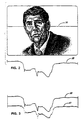
- FIG. 2 A graphic representation of a typical plot of luminance across a line of a video picture is shown in Figure 2.
- the luminance function of the pixels intersected by the scan line 36 is graphically represented by line 38.
- a graph of the decision points based upon comparison of one of the decision parameters with the corresponding adaptive difference threshold in a feature encoding technique results in stepped line 40, a sequence of horizontal straight lines across the luminance pattern. Each horizontal line represents a separate length of a specific color.
- a second approach which may be used to eliminate the non-essential details is a transition or slope encoding technique, which is illustrated in Figure 4.
- this technique the rate of change of the differences in the decision parameter between pixels is determined, and the rates of change of these differences are compared with an adaptive, prestored difference rate of change threshold to determine decision points or apex points. These change points or decision points are indicated as X's on line 39. They indicate the location of the next apex. "Run length" is defined as being the pixel distance between decision points, for both the feature encoding and slope encoding techniques.
- the luminance data results in a line 42 representing a series of apexes or slope decision points, which may be used for controlling the color segments between decision points.
- a drawing engine can produce a smooth transition of color values for the run length between decision points when the encoded information is to be retrieved.
- an initial color is transmitted, followed by as many sequences of run length and color values as are necessary to represent the picture frame content.
- the decision point detector 26 for determining decision points may alternatively be able to utilize either one of these methods for fixing the decision points in the color of the pixels in the picture, as each method has its respective advantages and disadvantages.
- the feature coding technique is typically more appropriate for pictures with a complexity of objects with distinctive edges or lines.
- the slope encoding technique is most suitable for encoding gradual transitions in shading or gradual color changes, but may require additional coding to represent complex pictures with images having many edges and lines.
- a sequence of thresholds will be compared with decision parameters, and the cumulative parameter (cum-diff) and an adaptive cumulative threshold will also be utilized in determining decision points, to account for those slow, gradual rates of change of luminance which would still result in an accumulated luminance change which is significant enough to merit identification of a decision point.
- the three component color codes are also operated on in the run length processor 28 to drop the two least significant bits from the six bit values for the color components, reducing each of the color components in the preferred mode to four bit digital words.
- the transition engine may also contain a predetermined color map representation of three-component colors, with an n-bit code corresponding to a particular color combination.
- the colors of the image are matched as closely as possible with the colors in the color map.
- the color codes could also be rounded.
- the preferred bit size for the reduced color components is four bits, just as the input digital word size for the color components from the analog front end can be of different sizes to vary the informational content, the reduced digital color components may also be of different sizes.
- a particular combination of digital word sizes for color components may include a reduced size for the red component, due to the recognition in the industry of the reduced perceptibility of this component.
- the second major portion of the image capture engine is the capture buffer memory (CBM) 29, which receives the encoded run lengths and reduced color components representing some 200 lines of data from the picture frame.
- CBM capture buffer memory
- lesser numbers of scan lines can be stored, such as 150 or 100 lines.
- the run length and color component information in the capture buffer memory is then transmitted to the video data processor 30, which accesses the run length and color data in the capture buffer memory by an access control 35, and operates as an interface to transform and transmit the video information in a further suitable for transmission by the modem 32, connected to the telephone 34, and which may include means for further compressing the video data, at 33.
- the video data may also be compared with a previous picture frame stored in an old picture memory 31.
- a simplification processor 33 of the video data processor 30 it is possible in a simplification processor 33 of the video data processor 30 to further analyze the difference between color values of pixels after the color codes have been truncated to provide the reduced color component codes, and to concatenate run lengths of such reduced color component codes which vary less than a given threshold value, or to further concatenate run lengths of the reduced color codes based upon variance of one or more of the decision parameters with respect to a corresponding threshold.
- the run length code is typically at a maximum of four bits to be compatible with run length and color code combinations of 16 bits, with 6 bit computer buses in the current implementation, concatentation of a sequence of pixels for each run length would be expected to permit coding of up to sixteen pixels per run length.
- the values 0 to 15 are used to represent run lengths of from 2 to 17 pixels, since run lengths of 0 and 1 are not meaningful.
- longer run lengths may be determined initially as well, as may be compatible with different capacity computer buses, to permit run lengths of greater than 4 bits and run length color code combinations greater than 16 bits.
- the limits of compression required for adequate smoothing of information in a real time sequencing of video pictures in telecommunication would be about 15 frames per second for transmission over conventional telephone lines. It would be possible to use a modem at 1200 bps (bits per second), but this would considerably slow the number of frames per second possible in the communication system. Ideally, the system is configured for half duplex mode, and a full duplex mode of configuration would be expected to require two telephone lines. Ideally the modem that is to be used is one which would utilize the largest bandwidth possible, and may be conventional 2400 bps or 9600 bps modem or special modems providing higher bit rates may be used.
- the invention may be also be adapted for use in compressing color video data on magnetic media, such as magnetic floppy discs which may be used in storing and communicating such data via computer systems, magnetic hard disks for image storage or short video movie sequences, or on video discs for video disc players which could transmit the information in the form of a full length movie.
- magnetic media such as magnetic floppy discs which may be used in storing and communicating such data via computer systems, magnetic hard disks for image storage or short video movie sequences, or on video discs for video disc players which could transmit the information in the form of a full length movie.
- the method and system for compressing color video data can achieve a significant elimination of extraneous noise introduced by a video camera, and can result in a significant improvement in coding of the minimum amount of information necessary to reconstruct color video picture frames in a real time sequencing of video pictures.
- the method and system for compressing color video data in a video communication system reduces the digital word sizes of data encoded, and codes only the minimum necessary decision points in scan lines in video color pictures for reception, storage, and/or retrieval by a system for decompressing and decoding the color video information.
Claims (17)
- Procédé de compression de données vidéo couleur pour plusieurs trames d'images vidéo, chaque trame d'image comprenant plusieurs lignes de balayage composées de plusieurs pixels, chaque ligne de balayage comprenant un pixel de début et un pixel de fin, et chaque pixel de ladite trame d'image comprenant trois signaux de composante de couleur numérique, respectivement, d'une première, deuxième, et troisième taille de mot numérique, ledit procédé comprenant, pour chaque pixel d'au moins une partie substantielle de chacune de plusieurs des lignes de balayage, les étapes :a) de détermination d'une valeur de luminance pour ledit pixel en fonction d'au moins l'un desdits signaux de composante de couleur numérique ;b) de détermination d'au moins un paramètre de décision représentant la variation de luminance pour ledit pixel, sous forme de la différence entre ladite valeur de luminance pour ledit pixel et ladite valeur de luminance pour au moins un autre pixel de la même ligne de balayage ;c) de comparaison de la valeur dudit au moins un paramètre de décision avec au moins un seuil réglable correspondant, pour déterminer si la valeur dudit au moins un paramètre de décision dépasse ledit au moins un seuil réglable correspondant, et de détermination, sur la base de ladite comparaison, si ledit pixel représente un point de décision représentant une variation prédéterminée de la luminance ;d) si le pixel représente un point de décision, de réduction de la taille de mot d'au moins l'un desdits trois signaux de composante de couleur numérique pour donner des signaux de composante de couleur numérique réduits correspondants pour ledit pixel ; ete) de codage dudit pixel comme l'un d'une séquence de pixels définie par une combinaison d'une séquence de pixels et desdits signaux de composante de couleur numérique correspondants, chacune desdites séquences de pixels commençant soit à un pixel de début de la ligne de balayage, soit à un pixel représentant un point de décision et se terminant soit à un pixel situé immédiatement avant un pixel représentant un point de décision soit à un pixel de fin de la ligne de balayage.
- Procédé selon la revendication 1, dans lequel ladite étape (c) de détermination du fait que ledit pixel représente un point de décision comprend, en outre, les étapes :de comparaison de la valeur dudit au moins un paramètre de décision avec la valeur dudit au moins un paramètre de décision pour un pixel adjacent ; etsi la valeur dudit au moins un paramètre de décision change de signe entre les pixels adjacents, de définition dudit pixel comme un point de décision.
- Procédé selon la revendication 1, dans lequel ladite étape (c) de détermination du fait que ledit pixel représente un point de décision comprend, en outre, les étapes :de détermination du taux de variation dudit au moins un paramètre de décision entre ledit pixel et au moins un autre pixel de la même ligne de balayage ;de comparaison dudit taux de variation avec un taux réglable de seuil de variation et ;de détermination du fait que ledit taux de variation excède ledit taux réglable correspondant de seuil de variation et de définition dudit pixel comme un point de décision si le taux de variation a une relation prédéterminée avec le taux réglable correspondant de seuil de variation.
- Procédé selon la revendication 3, dans lequel l'étape de détermination du taux de variation dudit au moins un paramètre de décision comprend, en outre, les étapes :de détermination d'un taux incrémentiel de variation dudit au moins un paramètre de décision entre ledit pixel et un autre pixel ; etde cumul dudit taux incrémentiel de variation avec le taux incrémentiel de variation de chaque pixel antérieur qui se trouve entre un point de décision déterminé antérieurement et ledit pixel, pour produire un paramètre de différence cumulée (CUMDIFF(i)) ;dans lequel l'étape de comparaison comprend, en outre, l'étape de comparaison dudit paramètre de différence cumulée avec un seuil de différence cumulée variable ; etdans lequel ladite étape de détermination du fait que ledit taux de variation dépasse ledit taux réglable correspondant de seuil de variation comprend, en outre, l'étape de détermination du fait que ledit paramètre de différence cumulée dépasse ledit seuil de différence cumulée réglable.
- Procédé selon la revendication 1, dans lequel l'étape de détermination de ladite valeur de luminance comprend la sommation de chacun desdits trois signaux de composante de couleur numérique.
- Procédé selon la revendication 5, dans lequel l'étape de détermination de ladite valeur de luminance comprend l'étape de calcul d'une somme pondérée desdits trois signaux de composante de couleur numérique.
- Procédé selon la revendication 1, dans lequel ledit un autre pixel est écarté dudit pixel de la distance d'un pixel.
- Procédé selon la revendication 1, dans lequel ledit un autre pixel est écarté dudit pixel de la distance de deux pixels.
- Procédé selon les revendications 7 ou 8, dans lequel on détermine un paramètre de décision cumulé en additionnant les valeurs de l'un dudit au moins un paramètre de décision pour ledit pixel et pour un autre pixel.
- Procédé selon les revendications 7 ou 8, dans lequel on détermine un paramètre de décision différence à partir de la différence entre les valeurs de l'un dudit au moins un paramètre de décision pour ledit pixel et pour un autre pixel.
- Procédé selon la revendication 1, comprenant, en outre, l'étape de concaténation de ladite séquence de pixels avec une seconde séquence de pixels, si lesdits signaux de composante de couleur numérique correspondants desdites séquences différent l'un de l'autre de moins qu'une valeur prédéterminée.
- Système pour comprimer des données vidéo couleur pour plusieurs trames d'images vidéo, chaque trame d'image comprenant plusieurs lignes de balayage composées de plusieurs pixels, chaque ligne de balayage comprenant un pixel de début et un pixel de fin, et chaque pixel de ladite trame d'image comprenant trois signaux de composante de couleur numérique, respectivement, d'une première, deuxième, et troisième taille de mot numérique, ledit système comprenant :a) un moyen de détermination (18) pour déterminer une valeur de luminance pour chaque pixel, d'au moins une partie substantielle de chacune de plusieurs des lignes de balayage, en fonction d'au moins l'un desdits signaux de composante de couleur numérique ;b) un moyen de détermination (24) pour déterminer au moins un paramètre de décision représentant la variation de luminance pour ledit pixel, sous forme de la différence entre ladite valeur de luminance pour ledit pixel et ladite valeur de luminance pour au moins un autre pixel de la même ligne de balayage ;c) un moyen de comparaison (26) pour comparer la valeur dudit au moins un paramètre de décision avec au moins un seuil réglable correspondant, pour déterminer si la valeur dudit au moins un paramètre de décision dépasse ledit au moins un seuil réglable correspondant, et pour déterminer, sur la base de ladite comparaison, si chaque dit pixel représente un point de décision représentant une variation prédéterminée de la luminance ;d) un moyen de réduction (28) pour réduire la taille de mot d'au moins l'un desdits trois signaux de composante de couleur numérique, pour chaque dit pixel qui représente un point de décision, pour donner des signaux de composante de couleur numérique réduits correspondants pour chaque dit pixel ; ete) un moyen de codage (26) pour coder chaque dit pixel comme l'un d'une séquence de pixels définie par une combinaison d'une séquence de pixels et desdits signaux de composante de couleur numérique correspondants, chacune desdites séquences de pixels commençant soit à un pixel de début de la ligne de balayage, soit à un pixel représentant un point de décision et se terminant soit à un pixel situé immédiatement avant un pixel représentant un point de décision soit à un pixel de fin de la ligne de balayage.
- Système selon la revendication 12, dans lequel ledit moyen (26) pour déterminer si ledit pixel représente un point de décision comprend, en outre,:a) un moyen de comparaison pour comparer la valeur dudit au moins un paramètre de décision avec la valeur dudit au moins un paramètre de décision pour un pixel adjacent ; et ;b) un moyen de détermination pour déterminer si la valeur dudit au moins un paramètre de décision change de signe entre des pixels adjacents, et pour définir ledit pixel comme un point de décision si la valeur dudit au moins un paramètre de décision change de signe.
- Système selon la revendication 12, dans lequel ledit moyen (26) pour déterminer si ledit pixel représente un point de décision comprend, en outre :a) un moyen de détermination pour déterminer le taux de variation dudit au moins un paramètre de décision entre chaque dit pixel et au moins un autre pixel de la même ligne de balayage ;b) un moyen de comparaison pour comparer chaque dit taux de variation avec un taux réglable de seuil de variation et ;c) un moyen de détermination pour déterminer si ledit taux de variation excède ledit taux réglable correspondant de seuil de variation et pour définir dudit pixel comme un point de décision si le taux de variation a une relation prédéterminée avec le taux réglable correspondant de seuil de variation.
- Système selon la revendication 12, dans lequel ledit moyen (18) de détermination de ladite valeur de luminance comprend un moyen pour additionner chacun desdits trois signaux de composante de couleur numérique.
- Système selon la revendication 15, dans lequel ledit moyen (18) de détermination de ladite valeur de luminance comprend un moyen pour calculer une somme pondérée desdits trois signaux de composante de couleur numérique.
- Système selon la revendication 12, comprenant, en outre, un moyen (33) pour concaténer ladite séquence de pixels avec une seconde séquence de pixels, si lesdits signaux de composante de couleur numérique correspondants desdites séquences différent les uns des autres de moins qu'un seuil de différence de couleur prédéterminé.
Applications Claiming Priority (4)
| Application Number | Priority Date | Filing Date | Title |
|---|---|---|---|
| US07/186,573 US4849807A (en) | 1988-04-27 | 1988-04-27 | Method and system for compressing color video feature encoded data |
| US07/186,569 US4816901A (en) | 1988-04-27 | 1988-04-27 | Method and system for compressing color video data |
| US186573 | 1988-04-27 | ||
| US186569 | 1988-04-27 |
Publications (3)
| Publication Number | Publication Date |
|---|---|
| EP0339938A2 EP0339938A2 (fr) | 1989-11-02 |
| EP0339938A3 EP0339938A3 (fr) | 1991-07-10 |
| EP0339938B1 true EP0339938B1 (fr) | 1996-07-03 |
Family
ID=26882225
Family Applications (1)
| Application Number | Title | Priority Date | Filing Date |
|---|---|---|---|
| EP89304115A Expired - Lifetime EP0339938B1 (fr) | 1988-04-27 | 1989-04-25 | Méthode et système de compression de données vidéo couleur codées |
Country Status (13)
| Country | Link |
|---|---|
| EP (1) | EP0339938B1 (fr) |
| JP (1) | JP2583628B2 (fr) |
| KR (1) | KR950009459B1 (fr) |
| AT (1) | ATE140114T1 (fr) |
| AU (1) | AU616262B2 (fr) |
| BR (1) | BR8906932A (fr) |
| CA (1) | CA1324654C (fr) |
| DE (1) | DE68926760T2 (fr) |
| FI (1) | FI896257A0 (fr) |
| IL (1) | IL90023A0 (fr) |
| NZ (1) | NZ228807A (fr) |
| PT (1) | PT90388B (fr) |
| WO (1) | WO1989010675A1 (fr) |
Cited By (1)
| Publication number | Priority date | Publication date | Assignee | Title |
|---|---|---|---|---|
| US7085424B2 (en) | 2000-06-06 | 2006-08-01 | Kobushiki Kaisha Office Noa | Method and system for compressing motion image information |
Families Citing this family (3)
| Publication number | Priority date | Publication date | Assignee | Title |
|---|---|---|---|---|
| US6453067B1 (en) * | 1997-10-20 | 2002-09-17 | Texas Instruments Incorporated | Brightness gain using white segment with hue and gain correction |
| USD843680S1 (en) | 2018-02-21 | 2019-03-26 | Towerstar Pets, Llc | Pet chew toy |
| US10888069B2 (en) | 2017-11-07 | 2021-01-12 | Towerstar Pets, Llc | Pet toy including apertures for receiving treats |
Family Cites Families (8)
| Publication number | Priority date | Publication date | Assignee | Title |
|---|---|---|---|---|
| FR2524740B1 (fr) * | 1981-06-02 | 1986-09-19 | Thomson Csf | Procede de compression d'une image numerisee |
| FR2529044B1 (fr) * | 1982-06-18 | 1986-06-20 | Inst Nat Rech Inf Automat | Procedes et dispositifs de telecommunications visuelles, notamment a l'usage des sourds |
| DE3236281A1 (de) * | 1982-09-30 | 1984-04-05 | Siemens AG, 1000 Berlin und 8000 München | Verfahren zur farbraumcodierung von digitalen farb-videosignalen und system zur durchfuehrung des verfahrens |
| US4743959A (en) * | 1986-09-17 | 1988-05-10 | Frederiksen Jeffrey E | High resolution color video image acquisition and compression system |
| US4772956A (en) * | 1987-06-02 | 1988-09-20 | Eastman Kodak Company | Dual block still video compander processor |
| US4774587A (en) * | 1987-06-02 | 1988-09-27 | Eastman Kodak Company | Still video transceiver processor |
| AU616006B2 (en) * | 1988-04-27 | 1991-10-17 | Bil (Far East Holdings) Limited | Method and system for compressing and decompressing digital color video statistically encoded data |
| CA1326898C (fr) * | 1988-04-27 | 1994-02-08 | John Music | Methode et systeme de decompression de donnees d'imagerie video couleur codees |
-
1989
- 1989-03-23 JP JP1503914A patent/JP2583628B2/ja not_active Expired - Lifetime
- 1989-03-23 AU AU33561/89A patent/AU616262B2/en not_active Ceased
- 1989-03-23 CA CA000594741A patent/CA1324654C/fr not_active Expired - Fee Related
- 1989-03-23 KR KR1019890702455A patent/KR950009459B1/ko not_active IP Right Cessation
- 1989-03-23 BR BR898906932A patent/BR8906932A/pt unknown
- 1989-03-23 WO PCT/US1989/001198 patent/WO1989010675A1/fr active Application Filing
- 1989-04-19 NZ NZ228807A patent/NZ228807A/xx unknown
- 1989-04-19 IL IL90023A patent/IL90023A0/xx unknown
- 1989-04-25 EP EP89304115A patent/EP0339938B1/fr not_active Expired - Lifetime
- 1989-04-25 DE DE68926760T patent/DE68926760T2/de not_active Expired - Fee Related
- 1989-04-25 AT AT89304115T patent/ATE140114T1/de not_active IP Right Cessation
- 1989-04-27 PT PT90388A patent/PT90388B/pt not_active IP Right Cessation
- 1989-12-22 FI FI896257A patent/FI896257A0/fi not_active IP Right Cessation
Cited By (1)
| Publication number | Priority date | Publication date | Assignee | Title |
|---|---|---|---|---|
| US7085424B2 (en) | 2000-06-06 | 2006-08-01 | Kobushiki Kaisha Office Noa | Method and system for compressing motion image information |
Also Published As
| Publication number | Publication date |
|---|---|
| FI896257A0 (fi) | 1989-12-22 |
| EP0339938A2 (fr) | 1989-11-02 |
| KR950009459B1 (ko) | 1995-08-22 |
| DE68926760D1 (de) | 1996-08-08 |
| EP0339938A3 (fr) | 1991-07-10 |
| PT90388B (pt) | 1994-04-29 |
| IL90023A0 (en) | 1989-12-15 |
| CA1324654C (fr) | 1993-11-23 |
| BR8906932A (pt) | 1990-12-11 |
| PT90388A (pt) | 1989-11-10 |
| AU616262B2 (en) | 1991-10-24 |
| JP2583628B2 (ja) | 1997-02-19 |
| KR900701130A (ko) | 1990-08-17 |
| NZ228807A (en) | 1991-02-26 |
| WO1989010675A1 (fr) | 1989-11-02 |
| ATE140114T1 (de) | 1996-07-15 |
| JPH02504099A (ja) | 1990-11-22 |
| DE68926760T2 (de) | 1996-10-31 |
| AU3356189A (en) | 1989-11-24 |
Similar Documents
| Publication | Publication Date | Title |
|---|---|---|
| US4816901A (en) | Method and system for compressing color video data | |
| EP0343790B1 (fr) | Système et méthode de télécommunication vidéo de compression et de décompression de données vidéo couleur numériques | |
| US4914508A (en) | Method and system for compressing and statistically encoding color video data | |
| US4857993A (en) | Method and system for decompressing digital color video statistically encoded data | |
| US4857991A (en) | Method and system for decompressing color video feature encoded data | |
| US4541012A (en) | Video bandwidth reduction system employing interframe block differencing and transform domain coding | |
| US7023915B2 (en) | Adaptive rate control for digital video compression | |
| EP0899959A2 (fr) | Méthode et dispositif de codage et de restauration de données d'image | |
| US5686961A (en) | Automatic video image data reduction and prioritization system and method | |
| US4843466A (en) | Method and system for decompressing color video slope encoded data | |
| US4849807A (en) | Method and system for compressing color video feature encoded data | |
| EP0339948B1 (fr) | Compression et décompression des données numériques de vidéo couleur codées statistiquement | |
| EP0339947B1 (fr) | Méthode et système de décompression de données vidéo couleur codées | |
| EP0339938B1 (fr) | Méthode et système de compression de données vidéo couleur codées | |
| JPH07284101A (ja) | 画像圧縮符号化装置 |
Legal Events
| Date | Code | Title | Description |
|---|---|---|---|
| PUAI | Public reference made under article 153(3) epc to a published international application that has entered the european phase |
Free format text: ORIGINAL CODE: 0009012 |
|
| AK | Designated contracting states |
Kind code of ref document: A2 Designated state(s): AT BE CH DE ES FR GB GR IT LI LU NL SE |
|
| PUAL | Search report despatched |
Free format text: ORIGINAL CODE: 0009013 |
|
| AK | Designated contracting states |
Kind code of ref document: A3 Designated state(s): AT BE CH DE ES FR GB GR IT LI LU NL SE |
|
| 17P | Request for examination filed |
Effective date: 19911224 |
|
| 17Q | First examination report despatched |
Effective date: 19931210 |
|
| RAP1 | Party data changed (applicant data changed or rights of an application transferred) |
Owner name: BIL (FAR EAST HOLDINGS) LIMITED (A HONG KONG CORPO |
|
| RAP3 | Party data changed (applicant data changed or rights of an application transferred) |
Owner name: BIL (FAR EAST HOLDINGS) LIMITED (A HONG KONG CORPO |
|
| GRAH | Despatch of communication of intention to grant a patent |
Free format text: ORIGINAL CODE: EPIDOS IGRA |
|
| GRAH | Despatch of communication of intention to grant a patent |
Free format text: ORIGINAL CODE: EPIDOS IGRA |
|
| GRAA | (expected) grant |
Free format text: ORIGINAL CODE: 0009210 |
|
| ITF | It: translation for a ep patent filed |
Owner name: BARZANO' E ZANARDO ROMA S.P.A. |
|
| AK | Designated contracting states |
Kind code of ref document: B1 Designated state(s): AT BE CH DE ES FR GB GR IT LI LU NL SE |
|
| PG25 | Lapsed in a contracting state [announced via postgrant information from national office to epo] |
Ref country code: LI Effective date: 19960703 Ref country code: GR Free format text: LAPSE BECAUSE OF FAILURE TO SUBMIT A TRANSLATION OF THE DESCRIPTION OR TO PAY THE FEE WITHIN THE PRESCRIBED TIME-LIMIT Effective date: 19960703 Ref country code: AT Effective date: 19960703 Ref country code: CH Effective date: 19960703 Ref country code: BE Effective date: 19960703 Ref country code: ES Free format text: THE PATENT HAS BEEN ANNULLED BY A DECISION OF A NATIONAL AUTHORITY Effective date: 19960703 |
|
| REF | Corresponds to: |
Ref document number: 140114 Country of ref document: AT Date of ref document: 19960715 Kind code of ref document: T |
|
| REF | Corresponds to: |
Ref document number: 68926760 Country of ref document: DE Date of ref document: 19960808 |
|
| ET | Fr: translation filed | ||
| PG25 | Lapsed in a contracting state [announced via postgrant information from national office to epo] |
Ref country code: SE Effective date: 19961003 |
|
| REG | Reference to a national code |
Ref country code: CH Ref legal event code: PL |
|
| PGFP | Annual fee paid to national office [announced via postgrant information from national office to epo] |
Ref country code: GB Payment date: 19970425 Year of fee payment: 9 |
|
| PG25 | Lapsed in a contracting state [announced via postgrant information from national office to epo] |
Ref country code: LU Free format text: LAPSE BECAUSE OF NON-PAYMENT OF DUE FEES Effective date: 19970430 |
|
| PLBE | No opposition filed within time limit |
Free format text: ORIGINAL CODE: 0009261 |
|
| STAA | Information on the status of an ep patent application or granted ep patent |
Free format text: STATUS: NO OPPOSITION FILED WITHIN TIME LIMIT |
|
| PGFP | Annual fee paid to national office [announced via postgrant information from national office to epo] |
Ref country code: NL Payment date: 19970529 Year of fee payment: 9 |
|
| 26N | No opposition filed | ||
| PG25 | Lapsed in a contracting state [announced via postgrant information from national office to epo] |
Ref country code: GB Free format text: LAPSE BECAUSE OF NON-PAYMENT OF DUE FEES Effective date: 19980425 |
|
| PG25 | Lapsed in a contracting state [announced via postgrant information from national office to epo] |
Ref country code: NL Free format text: LAPSE BECAUSE OF NON-PAYMENT OF DUE FEES Effective date: 19981101 |
|
| GBPC | Gb: european patent ceased through non-payment of renewal fee |
Effective date: 19980425 |
|
| NLV4 | Nl: lapsed or anulled due to non-payment of the annual fee |
Effective date: 19981101 |
|
| REG | Reference to a national code |
Ref country code: FR Ref legal event code: ST |
|
| REG | Reference to a national code |
Ref country code: FR Ref legal event code: RN |
|
| REG | Reference to a national code |
Ref country code: GB Ref legal event code: 728V |
|
| REG | Reference to a national code |
Ref country code: FR Ref legal event code: FC |
|
| PGFP | Annual fee paid to national office [announced via postgrant information from national office to epo] |
Ref country code: FR Payment date: 20000330 Year of fee payment: 12 |
|
| PGFP | Annual fee paid to national office [announced via postgrant information from national office to epo] |
Ref country code: DE Payment date: 20000331 Year of fee payment: 12 |
|
| PG25 | Lapsed in a contracting state [announced via postgrant information from national office to epo] |
Ref country code: FR Free format text: THE PATENT HAS BEEN ANNULLED BY A DECISION OF A NATIONAL AUTHORITY Effective date: 20010430 |
|
| PG25 | Lapsed in a contracting state [announced via postgrant information from national office to epo] |
Ref country code: DE Free format text: LAPSE BECAUSE OF NON-PAYMENT OF DUE FEES Effective date: 20020201 |
|
| REG | Reference to a national code |
Ref country code: FR Ref legal event code: ST |
|
| REG | Reference to a national code |
Ref country code: GB Ref legal event code: 7281 |
|
| PG25 | Lapsed in a contracting state [announced via postgrant information from national office to epo] |
Ref country code: IT Free format text: LAPSE BECAUSE OF NON-PAYMENT OF DUE FEES;WARNING: LAPSES OF ITALIAN PATENTS WITH EFFECTIVE DATE BEFORE 2007 MAY HAVE OCCURRED AT ANY TIME BEFORE 2007. THE CORRECT EFFECTIVE DATE MAY BE DIFFERENT FROM THE ONE RECORDED. Effective date: 20050425 |
|
| PGFP | Annual fee paid to national office [announced via postgrant information from national office to epo] |
Ref country code: IT Payment date: 20070616 Year of fee payment: 19 |
|
| PGRI | Patent reinstated in contracting state [announced from national office to epo] |
Ref country code: IT Effective date: 20091201 |
|
| PGRI | Patent reinstated in contracting state [announced from national office to epo] |
Ref country code: IT Effective date: 20091201 |