EP0339892B1 - Ignition coil-incorporated distributor for internal combustion engines - Google Patents
Ignition coil-incorporated distributor for internal combustion engines Download PDFInfo
- Publication number
- EP0339892B1 EP0339892B1 EP89304023A EP89304023A EP0339892B1 EP 0339892 B1 EP0339892 B1 EP 0339892B1 EP 89304023 A EP89304023 A EP 89304023A EP 89304023 A EP89304023 A EP 89304023A EP 0339892 B1 EP0339892 B1 EP 0339892B1
- Authority
- EP
- European Patent Office
- Prior art keywords
- housing
- core
- distributor
- shaft
- ignition coil
- Prior art date
- Legal status (The legal status is an assumption and is not a legal conclusion. Google has not performed a legal analysis and makes no representation as to the accuracy of the status listed.)
- Expired - Lifetime
Links
Images


Classifications
-
- F—MECHANICAL ENGINEERING; LIGHTING; HEATING; WEAPONS; BLASTING
- F02—COMBUSTION ENGINES; HOT-GAS OR COMBUSTION-PRODUCT ENGINE PLANTS
- F02P—IGNITION, OTHER THAN COMPRESSION IGNITION, FOR INTERNAL-COMBUSTION ENGINES; TESTING OF IGNITION TIMING IN COMPRESSION-IGNITION ENGINES
- F02P7/00—Arrangements of distributors, circuit-makers or -breakers, e.g. of distributor and circuit-breaker combinations or pick-up devices
- F02P7/02—Arrangements of distributors, circuit-makers or -breakers, e.g. of distributor and circuit-breaker combinations or pick-up devices of distributors
- F02P7/021—Mechanical distributors
- F02P7/026—Distributors combined with other ignition devices, e.g. coils, fuel-injectors
-
- H—ELECTRICITY
- H01—ELECTRIC ELEMENTS
- H01F—MAGNETS; INDUCTANCES; TRANSFORMERS; SELECTION OF MATERIALS FOR THEIR MAGNETIC PROPERTIES
- H01F38/00—Adaptations of transformers or inductances for specific applications or functions
- H01F38/12—Ignition, e.g. for IC engines
-
- F—MECHANICAL ENGINEERING; LIGHTING; HEATING; WEAPONS; BLASTING
- F02—COMBUSTION ENGINES; HOT-GAS OR COMBUSTION-PRODUCT ENGINE PLANTS
- F02B—INTERNAL-COMBUSTION PISTON ENGINES; COMBUSTION ENGINES IN GENERAL
- F02B1/00—Engines characterised by fuel-air mixture compression
- F02B1/02—Engines characterised by fuel-air mixture compression with positive ignition
- F02B1/04—Engines characterised by fuel-air mixture compression with positive ignition with fuel-air mixture admission into cylinder
Landscapes
- Engineering & Computer Science (AREA)
- Power Engineering (AREA)
- Chemical & Material Sciences (AREA)
- Combustion & Propulsion (AREA)
- Mechanical Engineering (AREA)
- General Engineering & Computer Science (AREA)
- Ignition Installations For Internal Combustion Engines (AREA)
Description
- This invention relates to a distributor for internal combustion engines, in which an ignition coil for internal combustion engines is incorporated in the distributor.
- An example of distributor for internal combustion engines is disclosed in Japanese Examined Patent Application Publication No. 60-18834/1985 corresponding to US-A-4 365 609, wherein the ignition coil-incorporated distributor comprises a housing, a rotor shaft rotatably supported by the housing, a cap fitted to the housing, a distributor part including a rotor electrode mounted on.a rotor top end of the rotor shaft and a side electrode mounted on the cap to face the rotor electrode with a gap therebetween, an ignition coil secured to the housing, a signal rotor secured to the rotor shaft, a magnetic pickup for picking up signals and interrupting current flowing in a primary coil of the ignition coil according to the signal to cause a secondary coil of the ignition coil to induce a high voltage, etc..
- In this ignition coil-incorporated distributor, the ignition coil is mounted on the housing at a position separated from the rotor shaft on one side a distance sufficient by means of screw passing through a hole formed in a core of the ignition coil in a direction perpendicular to the axis of the rotor shaft.
- In the distributor, a portion of the distributor in which the ignition coil is provided projects sideways to increase the dimensions of the distributor. Further, the weight of the ignition coil having a winding wound around an iron core thereof and provided at a side portion of the housing has a considerable percentage of a total weight of the distributor, so that the distributor becomes unstable with respect to the longitudinal axis thereof, and may give rise to troubles when it is mounted on a vehicle.
- Furthermore, the ignition coil is fixed by screw means at right angles to the direction of the longitudinal axis of the distributor. Consequently, parts of the distributor are screwed in various directions. This causes the distributor assembling operation to become complicated, and the assembling efficiency to decrease.
- Another example of the ignition coil-incorporated distributor is disclosed in Japanese Patent Laid-Open No. JP-A-61-231708, wherein an ignition coil comprises an iron core constructed of various parts, that is, a cylindrical core axially elongated, a pair of cruciform cores disposed on upper and lower sides of the cylindrical core, respectively, and having four arm portions radially extending, and plate-like cores at the tips of the arm portions of the cruciform cores to magnetically connect the upper and lower cruciform cores; and windings wound around the cylindrical core through which a rotor shaft of the distributor passes, the ignition coil being mounted on the upper side of a bearing for supporting the rotor shaft.
- In this distributor, the construction of the iron core is very complicated. Further, since the ignition coil is disposed at the upper side of the bearing for the rotor shaft, the size of the distributor increases in the direction of the longitudinal axis thereof by the height of the ignition coil. When the shaft is connected directly to a cam shaft in an engine, the distance between the bearings for the shaft decreases, so that the shaft shakes during the rotation thereof. This would cause interference of parts secured to the shaft with other parts facing the parts and generation of an unstable output signal.
- When the distributor is disposed laterally in an engine, that is, the longitudinal axis of the distributor is disposed horizontal, the center of gravity thereof in the direction of the longitudinal axis thereof separates from the position in which the distributor is fixed to the engine. Therefore, the distributor is readily vibrated, and the reliability of the strength thereof lowers.
- JP-A-55 072657 discloses a distributor having a core formed by a pipe and a winding is wound around the periphery of the pipe. As a result, the magnetic flux flows in an open circuit including an air path such that the magnetic flux flows around opposed ends of the pipe core and traverses both inside the pipe and outside the pipe. This reference forms the preamble of the
subject claim 1. - An object of the present invention is to provide a distributor for internal combustion engines, which is simple in construction, small-sized, mechanically stable. and capable of being easily assembled.
- According to this invention there is provided a distributor for internal combustion engines as claimed in
claim 1 herein. - Various features of the invention are defined in the dependent claims.
- It is preferable to incorporate the ignition coil in the housing so that the core of the ignition coil surrounds the outer side of a hollow shaft support portion upstanding from a bottom portion of the housing.
- In the present invention, the rotor shaft of the distributor is inserted through the annularly formed core of an ignition coil. Accordingly, the distributor as a whole is reduced in size and the center of gravity of the distributor in the radial direction can be set at a position very close to the longitudinal axis thereof. Moreover, the center of gravity of the distributor on its longitudinal axis can be set at a position in the vicinity of the position in which the distributor is fixed to the engine.
- The ignition coil is incorporated into the housing by fixing the core thereof to the housing by screw means in the direction in which the rotor shaft of the distributor extends, in the same manner as other parts.
- Therefore, in the present invention, the dimensions of the distributor as a whole decrease, and the distance between bearings for supporting the shaft can be set long, whereby the shaking of the shaft during the rotation thereof does not occur. The ignition coil is incorporated into the housing by a simple assembling operation with the stability and strength of the distributor kept sufficiently high.
-
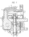
- Fig. 1 is a longitudinally sectional view showing the construction of an embodiment of distributor according to the present invention;
- Fig. 2 is a plan view showing the construction of the distributor in the embodiment;
- Fig. 3 is a perspective view showing the construction of an iron core of an ignition coil of the distributor in the embodiment;
- Fig. 4 is a perspective view showing the construction of winding in the ignition coil of the distributor in the embodiment;
- Fig. 5 is a perspective view showing the construction of the ignition coil in the embodiment;
- Fig. 6 is a sectional view of the ignition coil taken along a line VI-VI of Fig. 5;
- Fig. 7 is a perspective view showing the construction of a housing of the distributor in the embodiment;
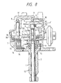
- Fig. 8 is a longitudinally sectional view of another embodiment of a distributor according to the present invention;
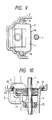
- Fig. 9 is a partial horizontally sectional view of another embodiment of a distributor according to the present invention; and
- Fig. 10 is a longitudinally sectional view of another embodiment of a distributor according to the present invention.
- An embodiment of a distributor for internal combustion engines according to the present invention will now be described in detail with reference to Figs. 1-7.
- The distributor has function of generating a crank angle position signal according to rotation of an internal combustion engine, generating a high voltage according to ignition timing signals generated, for example, in a control unit (not shown) based on the crank angle position signal and distributing it to an ignition plug of each cylinder of the engine. The distributor, as shown in Fig. 1, comprises a
housing 2, anignition coil 7 incorporated in thehousing 2, arotor shaft 1 rotatably supported by thehousing 2, asignal rotor 3 secured to theshaft 1 and having a plurality of projections extending radially, the number of which projections corresponds to the number of cylinders of the engine (not shown), asignal pickup device 5 for picking up a signal in corporation with thesignal rotor 3 as a crank angle position signal which is inputted into a control unit (not shown) to generate an ignition timing signal employing the crank angle position signal, etc. electric current flowing in a primary coil or winding of theignition coil 7 being interrupted according to the ignition timing signal to induce a high voltage in a secondary coil or winding of theignition coil 7, that is, at an output terminal of theignition coil 7, a rotor head 4 mounted on the top of theshaft 1, and acap 6, fitted to thehousing 2 so as to enclose thepickup device 5 andignition coil 7, and having acentral electrode 9 positioned at the central portion of the rotor head 4 and aside electrode 10 fixed thereto and positioned at one side of the rotor head 4 with a gas therebetween. - The
housing 2, as shown in Figs. 1 and 7, includes abottom portion 21, aside wall portion 22 upstanding from the periphery of thebottom portion 21, and ashaft support portion 23 projecting from thebottom portion 21 into the interior of thehousing 2, whereby anannular recess 24 is defined for accommodating theignition coil 7. Theshaft support portion 23 has a throughhole 25 formed therein in which, as shown in Fig. 1, a ball bearing 15 and a journal bearing 13 are fitted with an axial distance therebetween. Therotor shaft 1 is rotatably supported by thehousing 2 through thebearings - The
ignition coil 7, as shown in Figs. 3 to 6, comprises an iron core orcore 11 made of a plurality of core plates, and shaped annularly, a winding 12 including primary and secondary windings wound around a part of thecore 11, and acore electrode 8. Thecore 11 is inserted into the winding 12 as shown in Fig. 4 by inserting repeatedly each several plates of thecore 11 into the winding 12. - The
ignition coil 7 is set in therecess 24 in thehousing 2 in a manner that theshaft support portion 23 is inserted in or surrounded by the annular core 11of theignition coil 7. Theignition coil 7 hasfixing bores 16 formed in theiron core 11 thereof so as to extend in the direction which theshaft 1 extends, and theiron core 11 is fixed unitarily to thehousing 2 by setscrews 14 passing through thebores 16 and engaged withscrew bores 26 formed in thehousing 2. Theshaft 1 passes through and is surrounded by theiron core 11 of theignition coil 7. - As is shown in Fig. 1, the upper surface of the
core 11 of theignition coil 7 is in substantially the same level of the upper end of theshaft support portion 23 of thehousing 2, so that the axial length of the distributor is reduced and the distance between thebearings - The
ignition coil 7 has thecoil electrode 8 upstanding from the windings. Thecoil electrode 8 is inserted in a hole formed in thecap 6 at one side, and electrically connected with anelectrode member 91 embedded in thehousing 2 and connected to thecentral electrode 9. Aspace 18 is formed between thecoil electrode 8 and an inside wall of the hole for accommodating thecoil electrode 8, and is made labyrinthic whereby the length of the labyrinthic space from the winding portion to a contact portion with theelectrode member 91 is made long, so that atmosphere outside the distributor is unlikely to be influenced. - The operation of the embodiment of the above-described construction will now be described.
- When the
shaft 1 is rotated synchronously with the rotation of the engine (not shown), the rotation of thesignal rotor 3 is detected as a crank angle position signal of the engine, by thesignal pickup device 5 or signal detector, and this crank angle position signal is inputted into the control unit (not shown). This control unit outputs an ignition timing signal for the engine into the distributor, and this ignition timing signal causes a high voltage to be induced at the output terminal of the ignition coil. - The high voltage thus induced in the
ignition coil 7 is applied from thecoil electrode 8 to anelectrode 41 of the rotor head 4 through theelectrode member 91 and thecentral electrode 9 on thecap 6 and discharged from the rotor head 4 to theside electrodes 10 on thecap 6. Owing to this discharge, the high voltage is applied to the ignition plug in each cylinder of the engine (not shown). - According to this embodiment, the distributor as a whole can be formed to smaller dimensions or compact since the
shaft support portion 23 of thehousing 2 is positioned on the inner side of theannular iron core 11 of theignition coil 7. The center of gravity of the distributor is set in the substantially central portion of theshaft 1 in the radial direction, and in a position in the vicinity of the position in which the distributor is set in the engine, in the direction in which theshaft 1 extends. Accordingly, the distributor can be set in the engine stable and operated without being vibrated, and the strength of the distributor is improved. - Moreover, the distance between the
bearings shaft 1 can be set long, and this enables the shaking of theshaft 1, rotor head 4 and signalrotor 3 to be minimized, and stable crank angle position signal and discharge output signal to be supplied. - Since the
ignition coil 7 is fixed at itsiron core 11 to the housing by theset screws 14 in the direction in which theshaft 1 extends, the assembling efficiency is very high, and the manufacturing cost can be reduced. - The distributor is of the type wherein the distributor is directly connected to an engine cam.
- Next, another embodiment of the ignition coil-incorporated distributor according to the present invention is described referring to Fig. 8.
- In Fig. 8, a
shaft 1 is inserted at its one end portion into ahousing 2 and supported rotatably on aball bearing 15, theshaft 1 being rotated synchronously with a crankshaft (not shown) of a gasoline engine at a speed half as high as that of this crankshaft. - A
signal rotor 3 is secured to theshaft 1 and has a plurality of projections radially projecting the number of which is equal to the number of engine cylinders. - An
electromagnetic pickup device 5 comprising acoil 52 and afield magnet 51 is provided in opposition to and in a spaced state from thesignal rotor 3, and fixed to thehousing 2. - A voltage induced in the
electromagnetic pickup coil 52 in accordance with the rotation of thesignal rotor 3 is used to control the interruption of current flowing in a primary winding of theignition coil 7 through anignition amplifier 53. - When the current flowing in the primary winding is discontinued, a high voltage is induced in a secondary winding of the
ignition coil 7 and is distributed to ignition plugs (not shown) through anelectrode 41 of a rotor head 4 and anelectrode 10 provided on acap 6. - A
core 71 of theignition coil 7 is held between a pair ofcore holders core 71. - These two
core holders core holders housing 2. - When a
hook 77 is provided on thecore holder 75, thepresent ignition coil 7 can be hooked up conveniently when it is taken out. Also, when theignition coil 7 is installed in thehousing 2, it can be gripped at thehook 77 and placed properly. - A box type core holder (not shown) may be formed in place of the
core holders core 71 of the ignition coil held between the core holder andhousing 2. When the core holder is formed in this manner, a one piece core holder can be obtained. - If set screw holes are made along a chain line A in the
core 71, and, if thecore 71 is fastened to thehousing 2 with set screws (not shown), a hollow is formed in thecore 71, so that the magnetic flux passage is blocked. Moreover, the efficiency of operations for inserting and tightening set screws in this direction becomes very low. - It is very difficult to provide screw holes, which extend in the direction of the chain line A, in the
housing 2. - On the other hand, the
set screws 79 in this embodiment extend in parallel with theshaft 1. Accordingly, the forming of screw holes and the inserting and tightening of the set screws can be done easily, and this distributor is suitable to be produced automatically. The reason why the positions in which the set screws are arranged and the direction in which these screws are extended can be determined favorably resides in that thecore 71 is set via thecore holder - Fig. 9 shows another embodiment of the present invention, and is a partial sectional view taken along a plane extending at right angles to the
shaft 1. - A
core holder 78 in this embodiment is welded to acore 71 of anignition coil 7. Even in such a structure, the same effect as in the previous embodiment of Fig. 8 can be obtained. - Fig. 10 shows still another embodiment of the present invention. A
core 71 of anignition coil 7 and acore holder 74 are provided with through holes at which thecore 71 andcore holder 74 are fitted loosely around ashaft 1. The through holes allow theshaft 1 to be passed therethrough. According to this embodiment, the core 72 can be held in a miniaturized housing by effectively utilizing a space around theshaft 1 in thehousing 2. The core 72 in this embodiment is fitted in a recessedseat 27 provided in thehousing 2, and it is fixed by being pressed by thecore holder 74 consisting of a holding metal type flat plate. According to this embodiment, thecore holder 74 can be formed in a simple shape, and the manufacturing cost is low. - According to the present invention, the distributor can be made compact and set in the engine so that the distributor can be operated stably. This distributor has a high assembling efficiency, and is suitable to be produced automatically. Moreover, the construction of the constituent parts is simple.
Claims (8)
- A distributor for internal combustion engines, said distributor comprising a housing (2) including a support portion (23) for supporting a bearing (15) for rotatably supporting a shaft in said housing, said support portion (23) being in said housing (2), a shaft (1) synchronously rotatable with the rotation of the engine, an ignition coil (7) including a core (11) and a winding (12) wound around said core, for generating a high voltage for firing an ignition plug in each cylinder of the engine, said core (11) having an annular configuration and being disposed in said housing (2) so as to surround said shaft (1) and means (9, 10, 41) for distributing the high voltage to the ignition plug of each cylinder, characterised in that said core (11) is generally toroidally shaped, and said winding (12) is wound around a part of the generally toroidally configured core (11) thereby forming a toroidal magnetic flux flow path of similar shape to said core.
- A distributor according to claim 1, wherein said support portion (23) projects into the interior of said housing (2) from an interior wall of said housing and is surrounded by said core (11), and the bearing (15) is provided on an inner side of said annular core (11).
- A distributor according to claim 1 or 2, wherein screw means (14, 79) for fixing said ignition coil (7) to said housing are provided, said screw means including screws (14, 79) screwed in a direction parallel to said shaft for fastening said annular core to said housing.
- A distributor according to any preceding claim, wherein said housing (2) comprises a bottom portion (21), a side wall portion (22) upstanding from the periphery of said bottom portion, a hollow shaft support portion projecting from said bottom portion into the interior of said housing and having therein bearings (13) for rotatably supporting said shaft (1), and said annular core (11) of said ignition coil surrounds said shaft support portion of said housing.
- A distributor according to any preceding claim, wherein upper surfaces of said annular core (11) and said shaft support portion (23) are in substantially the same plane.
- A distributor according to any preceding claim, wherein said housing (2) has an annular recess (24) formed around said shaft support portion (23), and said annular core (11) of said ignition coil is fitted in said recess of said housing.
- A distributor according to any preceding claim, wherein said ignition coil (7) further comprises a coil electrode (8) upstanding from said winding portion, said ignition coil being set in an annular recess (24) of said housing (2) so that said coil electrode is upstanding.
- A distributor according to claim 7, wherein a labyrinthic space (18) is provided between an elongated hole formed in a cap (6) arranged to be fitted to said housing and said upstanding coil electrode (8) is inserted in said elongated hole to electrically contact with a rotor head electrode (41) mounted on said shaft (1).
Applications Claiming Priority (4)
| Application Number | Priority Date | Filing Date | Title |
|---|---|---|---|
| JP101227/88 | 1988-04-26 | ||
| JP10122788A JPH0633760B2 (en) | 1988-04-26 | 1988-04-26 | Distributor with integrated ignition coil for internal combustion engine |
| JP190644/88 | 1988-08-01 | ||
| JP63190644A JP2628703B2 (en) | 1988-08-01 | 1988-08-01 | Ignition coil integrated type distributor |
Related Child Applications (2)
| Application Number | Title | Priority Date | Filing Date |
|---|---|---|---|
| EP92120484.8 Division-Into | 1989-04-24 | ||
| EP19920120484 Division EP0536811A3 (en) | 1988-04-26 | 1989-04-24 | Ignition coil-incorporated distributor for internal combustion engines |
Publications (3)
| Publication Number | Publication Date |
|---|---|
| EP0339892A2 EP0339892A2 (en) | 1989-11-02 |
| EP0339892A3 EP0339892A3 (en) | 1990-04-18 |
| EP0339892B1 true EP0339892B1 (en) | 1997-03-05 |
Family
ID=26442130
Family Applications (2)
| Application Number | Title | Priority Date | Filing Date |
|---|---|---|---|
| EP19920120484 Withdrawn EP0536811A3 (en) | 1988-04-26 | 1989-04-24 | Ignition coil-incorporated distributor for internal combustion engines |
| EP89304023A Expired - Lifetime EP0339892B1 (en) | 1988-04-26 | 1989-04-24 | Ignition coil-incorporated distributor for internal combustion engines |
Family Applications Before (1)
| Application Number | Title | Priority Date | Filing Date |
|---|---|---|---|
| EP19920120484 Withdrawn EP0536811A3 (en) | 1988-04-26 | 1989-04-24 | Ignition coil-incorporated distributor for internal combustion engines |
Country Status (4)
| Country | Link |
|---|---|
| US (2) | US4979486A (en) |
| EP (2) | EP0536811A3 (en) |
| KR (1) | KR900016610A (en) |
| DE (1) | DE68927807T2 (en) |
Families Citing this family (12)
| Publication number | Priority date | Publication date | Assignee | Title |
|---|---|---|---|---|
| JPH03160154A (en) * | 1989-11-15 | 1991-07-10 | Hitachi Ltd | Ignition coil integral type distribution and method for integrally mounting ignition coil supporting member and ignition coil used therein to distributor |
| KR950000233B1 (en) * | 1990-09-28 | 1995-01-12 | 미쓰비시덴키 가부시키가이샤 | Distributor assembly for internal combustion engine |
| US5351670A (en) * | 1991-11-21 | 1994-10-04 | Nippondenso Co., Ltd. | Ignition distributor for an internal combustion engine |
| KR970003158B1 (en) * | 1992-06-15 | 1997-03-14 | 미쓰비시덴키 가부시키가이샤 | Ignitor for an internal combustion engine |
| US5285761A (en) * | 1992-09-03 | 1994-02-15 | Ford Motor Company | Ignition coil |
| US5335642A (en) * | 1992-09-03 | 1994-08-09 | Ford Motor Company | Ignition coil |
| US5241941A (en) * | 1992-09-03 | 1993-09-07 | Ford Motor Company | Ignition coil |
| JPH06325955A (en) * | 1993-05-13 | 1994-11-25 | Hitachi Ltd | Ignition device for internal combustion engine, and ignition device mounting type distributor |
| JP3207076B2 (en) * | 1995-04-24 | 2001-09-10 | 三菱電機株式会社 | Ignition device for internal combustion engine |
| US5692483A (en) * | 1995-06-30 | 1997-12-02 | Nippondenso Co., Ltd. | Ignition coil used for an internal combustion engine |
| IL128083A (en) | 1999-01-17 | 2001-09-13 | Diuk Energy | Adjustable height concrete expansion joints |
| US20110132339A1 (en) * | 2009-12-04 | 2011-06-09 | Jerry Hoffmann | Multiple Coil Distributor and Method of Use Thereof |
Family Cites Families (18)
| Publication number | Priority date | Publication date | Assignee | Title |
|---|---|---|---|---|
| US2885458A (en) * | 1959-05-05 | Combination ignition coil and ignition distributor | ||
| US1277388A (en) * | 1918-03-06 | 1918-09-03 | Westinghouse Electric & Mfg Co | Ignition mechanism. |
| US1458548A (en) * | 1920-05-01 | 1923-06-12 | Simplex Ignition Corp | Igniter |
| US2057240A (en) * | 1934-09-10 | 1936-10-13 | Mallory Marion | Ignition coil and distributor |
| CH190242A (en) * | 1936-06-06 | 1937-04-15 | Scintilla Ag | Magnetic electric igniter with attached power distributor. |
| US2224744A (en) * | 1940-02-10 | 1940-12-10 | Piffath Peter | Ignition device |
| US2346094A (en) * | 1941-05-07 | 1944-04-04 | Fairbanks Morse & Co | Ignition device |
| US2377353A (en) * | 1943-08-25 | 1945-06-05 | Messerschmidt Charles | Ignition apparatus |
| US2426784A (en) * | 1945-06-02 | 1947-09-02 | Messerschmidt Charles | Ignition apparatus |
| US2552212A (en) * | 1949-08-13 | 1951-05-08 | Gen Electric | High-frequency ignition system |
| FR2432096A1 (en) * | 1978-07-26 | 1980-02-22 | Abg Semca | Electronic ignition system for vehicle IC engine - has power amplifier Darlington pair associated with Hall effect sensor determining shaft position |
| JPS5572657A (en) * | 1978-11-29 | 1980-05-31 | Hitachi Ltd | Distributor |
| FR2511184A1 (en) * | 1981-08-06 | 1983-02-11 | Ducellier & Cie | PROCESS FOR OBTAINING A COIL WITH A CLOSED MAGNETIC CIRCUIT AND A PERMANENT MAGNET FOR THE IGNITION OF AN INTERNAL COMBUSTION ENGINE |
| JPS5825580A (en) * | 1981-08-07 | 1983-02-15 | Nippon Denso Co Ltd | Ignition system with ignition coil integrating type ignition distributor |
| JPS6018834A (en) * | 1983-07-13 | 1985-01-30 | Hitachi Ltd | Tape drive switch of tape recorder |
| JPS61231708A (en) * | 1985-04-05 | 1986-10-16 | Mitsubishi Electric Corp | Ignition coil |
| JPS62258172A (en) * | 1986-05-06 | 1987-11-10 | Hitachi Ltd | Ignition coil housing type distributor |
| JPS62294774A (en) * | 1986-06-13 | 1987-12-22 | Mitsubishi Electric Corp | Distributor for ignition of internal combustion engine |
-
1989
- 1989-04-19 KR KR1019890005161A patent/KR900016610A/en not_active Application Discontinuation
- 1989-04-21 US US07/341,762 patent/US4979486A/en not_active Expired - Lifetime
- 1989-04-24 EP EP19920120484 patent/EP0536811A3/en not_active Withdrawn
- 1989-04-24 DE DE68927807T patent/DE68927807T2/en not_active Expired - Fee Related
- 1989-04-24 EP EP89304023A patent/EP0339892B1/en not_active Expired - Lifetime
-
1990
- 1990-04-30 US US07/516,312 patent/US5036827A/en not_active Expired - Lifetime
Also Published As
| Publication number | Publication date |
|---|---|
| DE68927807T2 (en) | 1997-08-21 |
| US4979486A (en) | 1990-12-25 |
| EP0339892A2 (en) | 1989-11-02 |
| KR900016610A (en) | 1990-11-14 |
| EP0339892A3 (en) | 1990-04-18 |
| EP0536811A3 (en) | 1993-09-15 |
| DE68927807D1 (en) | 1997-04-10 |
| EP0536811A2 (en) | 1993-04-14 |
| US5036827A (en) | 1991-08-06 |
Similar Documents
| Publication | Publication Date | Title |
|---|---|---|
| EP0339892B1 (en) | Ignition coil-incorporated distributor for internal combustion engines | |
| US7709982B2 (en) | Brushless motor | |
| US6294973B1 (en) | Ignition coil for internal combustion engine | |
| EP1688617A1 (en) | Twin spark pencil coil | |
| JPH03154311A (en) | Ignition coil | |
| US7095306B2 (en) | Ignition coil having rigid mounting structure | |
| US4453526A (en) | Ignition system including ignition distributor integrated with ignition coil | |
| EP0033136B1 (en) | Distributor assembly having an ignition coil therein | |
| US6192873B1 (en) | Ignition coil having spring for connecting the same to spark plug | |
| EP2770619A2 (en) | Rotating electric machine, engine, and vehicle | |
| JP2003297654A (en) | Internal combustion engine igniter | |
| JPH08232825A (en) | Ignition device integral with combustion pressure sensor | |
| US7236074B2 (en) | Ignition coil | |
| JP2013115075A (en) | Ignition coil for internal combustion engine | |
| JPH059501Y2 (en) | ||
| JPH09246074A (en) | Ignition coil for internal combustion engine | |
| US20220099062A1 (en) | Crankshaft driven flywheel magneto generator with circular winding for power supply in handheld batteryless combustion engines | |
| JP4494296B2 (en) | Ignition device for internal combustion engine | |
| JP3795639B2 (en) | Ignition coil for internal combustion engine | |
| JPS5916537Y2 (en) | Ignition distributor | |
| JPH0510543Y2 (en) | ||
| JPH0450461Y2 (en) | ||
| JP2522226B2 (en) | Electromagnetic rotation sensor | |
| JPH036871Y2 (en) | ||
| JP2628703B2 (en) | Ignition coil integrated type distributor |
Legal Events
| Date | Code | Title | Description |
|---|---|---|---|
| PUAI | Public reference made under article 153(3) epc to a published international application that has entered the european phase |
Free format text: ORIGINAL CODE: 0009012 |
|
| 17P | Request for examination filed |
Effective date: 19890518 |
|
| AK | Designated contracting states |
Kind code of ref document: A2 Designated state(s): DE FR GB |
|
| PUAL | Search report despatched |
Free format text: ORIGINAL CODE: 0009013 |
|
| AK | Designated contracting states |
Kind code of ref document: A3 Designated state(s): DE FR GB |
|
| 17Q | First examination report despatched |
Effective date: 19920702 |
|
| GRAG | Despatch of communication of intention to grant |
Free format text: ORIGINAL CODE: EPIDOS AGRA |
|
| GRAH | Despatch of communication of intention to grant a patent |
Free format text: ORIGINAL CODE: EPIDOS IGRA |
|
| GRAH | Despatch of communication of intention to grant a patent |
Free format text: ORIGINAL CODE: EPIDOS IGRA |
|
| RHK1 | Main classification (correction) |
Ipc: F02P 7/02 |
|
| GRAH | Despatch of communication of intention to grant a patent |
Free format text: ORIGINAL CODE: EPIDOS IGRA |
|
| GRAA | (expected) grant |
Free format text: ORIGINAL CODE: 0009210 |
|
| AK | Designated contracting states |
Kind code of ref document: B1 Designated state(s): DE FR GB |
|
| XX | Miscellaneous (additional remarks) |
Free format text: TEILANMELDUNG 92120484.8 EINGEREICHT AM 24/04/89. |
|
| REF | Corresponds to: |
Ref document number: 68927807 Country of ref document: DE Date of ref document: 19970410 |
|
| ET | Fr: translation filed | ||
| PLBE | No opposition filed within time limit |
Free format text: ORIGINAL CODE: 0009261 |
|
| STAA | Information on the status of an ep patent application or granted ep patent |
Free format text: STATUS: NO OPPOSITION FILED WITHIN TIME LIMIT |
|
| 26N | No opposition filed | ||
| REG | Reference to a national code |
Ref country code: GB Ref legal event code: IF02 |
|
| PGFP | Annual fee paid to national office [announced via postgrant information from national office to epo] |
Ref country code: FR Payment date: 20020327 Year of fee payment: 14 |
|
| PGFP | Annual fee paid to national office [announced via postgrant information from national office to epo] |
Ref country code: GB Payment date: 20020402 Year of fee payment: 14 |
|
| PGFP | Annual fee paid to national office [announced via postgrant information from national office to epo] |
Ref country code: DE Payment date: 20020628 Year of fee payment: 14 |
|
| PG25 | Lapsed in a contracting state [announced via postgrant information from national office to epo] |
Ref country code: GB Free format text: LAPSE BECAUSE OF NON-PAYMENT OF DUE FEES Effective date: 20030424 |
|
| PG25 | Lapsed in a contracting state [announced via postgrant information from national office to epo] |
Ref country code: DE Free format text: LAPSE BECAUSE OF NON-PAYMENT OF DUE FEES Effective date: 20031101 |
|
| GBPC | Gb: european patent ceased through non-payment of renewal fee | ||
| PG25 | Lapsed in a contracting state [announced via postgrant information from national office to epo] |
Ref country code: FR Free format text: LAPSE BECAUSE OF NON-PAYMENT OF DUE FEES Effective date: 20031231 |
|
| REG | Reference to a national code |
Ref country code: FR Ref legal event code: ST |