EP0339714A1 - Electron tube device and electron tube - Google Patents
Electron tube device and electron tube Download PDFInfo
- Publication number
- EP0339714A1 EP0339714A1 EP89200953A EP89200953A EP0339714A1 EP 0339714 A1 EP0339714 A1 EP 0339714A1 EP 89200953 A EP89200953 A EP 89200953A EP 89200953 A EP89200953 A EP 89200953A EP 0339714 A1 EP0339714 A1 EP 0339714A1
- Authority
- EP
- European Patent Office
- Prior art keywords
- electron tube
- line cathode
- tube device
- temperature
- line
- Prior art date
- Legal status (The legal status is an assumption and is not a legal conclusion. Google has not performed a legal analysis and makes no representation as to the accuracy of the status listed.)
- Granted
Links
Images


Classifications
-
- H—ELECTRICITY
- H01—ELECTRIC ELEMENTS
- H01J—ELECTRIC DISCHARGE TUBES OR DISCHARGE LAMPS
- H01J1/00—Details of electrodes, of magnetic control means, of screens, or of the mounting or spacing thereof, common to two or more basic types of discharge tubes or lamps
-
- H—ELECTRICITY
- H01—ELECTRIC ELEMENTS
- H01J—ELECTRIC DISCHARGE TUBES OR DISCHARGE LAMPS
- H01J1/00—Details of electrodes, of magnetic control means, of screens, or of the mounting or spacing thereof, common to two or more basic types of discharge tubes or lamps
- H01J1/02—Main electrodes
- H01J1/13—Solid thermionic cathodes
- H01J1/135—Circuit arrangements therefor, e.g. for temperature control
Definitions
- the invention relates to an electron tube device comprising an electron tube having at least one line cathode, and an electric power source for the supply of power pulses to the line cathode.
- Such an electron tube device is known from United States Patent Specification 4,167,690, in which a description is given of a display device having a line cathode which is heated by means of power pulses. Between each consecutive pair of pulses there is an interval. During this interval an electron flow is extracted from the line cathode. This electron flow is modulated by a modulation system and an image is displayed on a display screen.
- an electron tube device of the type described in the opening paragraph is characterized in that the electron tube device comprises determination means for determining a value of a physical quantity depending on the temperature of the line cathode during a power pulse, comparison means for comparing the value with a reference value and for supplying a control signal, and termination means for ending the relevant power pulse in dependence on the control signal.
- the invention is based on the insight that the temperature of the line cathode does not only depend on the power supplied to the line cathode but also on the heat dissipated by the line cathode and other factors such as the mass of the line cathode.
- the line cathode dissipates heat by, inter alia , radiation and conduction.
- the amount of radiation heat depends, amongst others, on the temperatur, the emissivity and the size of the surface of the line cathode and the ambient temperature, i.e., the temperature of the surroundings on the line cathode.
- the amount of heat which is conducted away depends, inter alia , on the manner in which the line cathode is arranged in the electron tube, the temperature of the line cathode and the ambient temperature. If the power supplied remains constant, changes in, for example, the ambient temperature or the emissivity of the surface of the line cathode lead to changes in the temperature of the line cathode and, thus, to changes in the number of electrons emitted.
- the power supplied to the line cathode is constant.
- the temperature of the line cathode is subject to changes during operation.
- the temperature of the line cathode cannot be accurately predicted.
- the value of a temperature-dependent physical quantity is determined during a power pulse, and the power pulse is ended if a comparison of this value with a reference value shows that the temperature of the line cathode exceeds a temperature which corresponds to the reference value.
- the power supplied to the line cathode depends on the value of the physical quantity and, hence, on the temperature of the line cathode, as a result of which an improved adjustment of the number of electrons emitted by the line cathode is achieved and the transient time, i.e. the time during which important intitial variations in the number of electrons emitted occur, is reduced.
- a preferred embodiment of the line-cathode arrangement in accordance with the invention is characterized in that the determination means can suitably be used for determining a physical quantity of the line cathode.
- the temperature of the line cathode is determined in a direct manner.
- the temperature of the line cathode can be determined indirectly, for example via the ambient temperature of the line cathode; the disadvantage of indirect temperature control relative to direct temperature determination is that both the possibility and the extent of the changes in the temperature of the line cathode are increased.
- Temperature-dependent properties of the line cathode may be, amongst others, the tensile load on the wire, the length of the wire, the electromagnetic radiation emitted, of which both the intensity and the frequency distribution are temperature-dependent, the number of electrons emitted per unit of time by the line cathode and the velocity distribution among these electrons, and the electrical resistance.
- a further embodiment of an electron tube device in accordance with the invention is characterized in that the determination means are at least partly present in the electron tube and are suitable for determining the number of electrons emitted per unit of time by the line cathode.
- the number of electrons emitted per unit of time is determined during a pulse and compared with a reference quantity; if the number is larger than the reference quantity the power pulse is ended.
- the number of electrons emitted per unit of time substantially corresponds to the desired number.
- This is a simple and direct manner of controlling the number of electrons emitted per unit of time.
- a disadvantage is that additional elements are accommodated in the electron tube, which are provided with connections. Consequently, the construction of the electron tube becomes more complicated and, moreover, there is a risk that the determination means or their connections may break. Since these means are present in the electron tube, it is difficult, or even impossible, to repair them.
- An alternative embodiment of an electron tube device in accordance with the invention is characterized in that the determination means comprise means for determining the resistance.
- an electron tube device in which the power source can suitably be used to apply a voltage drop across the line cathode within power pulses having a substantially constant current value, is characterized in that the means for determining the resistance comprise an arrangement for determining the voltage drop across the line cathode.
- a further embodiment of an electron tube device in accordance with the invention is characterized in that the electron tube device comprises calibration means for determining a calibration value of the physical quantity, at a calibration temperature, and means for determining the reference value in dependence on the calibration value. If the calibration value has been determined at a known calibration temperature, the dependence of the physical quantity on the temperature is known. The reference value can be determined more accurately and compensated for changes in the calibration value during the life cycle of the electron tube device.
- the invention can advantageously be used, in particular, in an electron tube device in which the electron tube is provided with a system of line cathodes.
- the number of electrons emitted per unit of time by the different line cathodes is equal to the extent possible so that there are no differences in intensity.
- FIG. 1 shows an electron tube device known from the present state of the art.
- An electron tube device 1 comprises an electron tube 2 containing a line cathode 3, and a power source 4.
- Power pulses generated by the power source 4 are supplied to the line cathode 3.
- the pulse duration is approximately 10 ⁇ s, the interval, i.e. the time between the end of a power pulse and the beginning of the next power pulse is approximately 50 ⁇ s.
- no voltage drop is applied across the line cathode.
- the disadvantage of this known method is that the temperature of the line cathode cannot be accurately controlled and is subject to changes because the temperature does not only depend on the power supplied.
- a further disadvantage of the known state-of-the-art method is that if use is made of power pulses having a constant current value there is the risk of an excessive increase of the temperature of the line cathode. This disadvantage will be described hereinbelow by means of Fig. 7.
- Fig. 2 shows an electron tube device in accordance with the invention.
- Power pulses generated by power source 4 are supplied to the line cathode 3.
- the value of a physical quantity which depends on the temperature of the line cathode is determined by menas of a determination means 5.
- a comparison means 6 the value is compared with a reference value G.
- a control signal T is generated by the comparison means 6 and is supplied to a termination means B. If the control signal indicates that the temperature of the line cathode exceeds a reference temperature corresponding to the reference value, the power pulse is ended, i.e. the voltage drop across the line cathode 3 is reduced to substantially nil.
- the termination means B may be contained in the power source 4.
- Fig. 3 is a diagrammatic view of an embodiment of an electron tube device in accordance with the invention.
- Determination means 5 comprise a portion 5 a in the electron tube. This portion is used to measure the number of electrons emitted per unit of time.
- the comparison means 6 the number is compared with a reference number. If the number exceeds the reference number, the power pulse is ended.
- Fig. 4 is an alternative embodiment of an electron tube device in accordance with the invention.
- Power pulses having a constant current are supplied to a line cathode 7 by a current source 8.
- a current source 8 supplies the voltage drop across the line cathode 7 by a current source 8.
- This voltage drop is compared with a calibration value V G in a comparison means 10.
- the resistance changes as the temperature of the line cathode increases, in general the resistance will increase.
- the voltage drop across the line cathode increases. If the voltage drop exceeds the calibration value V G the current through the line cathode is reduced to nil by means of a control signal T, and the power pulse is ended.
- Fig. 5 shows an alternative embodiment of the electron tube device in accordance with the invention.
- Power pulses having a constant voltage are applied to a line cathode 11 by a voltage source 12.
- the current passing through the line cathode is measured by means of a current meter 13.
- This current is compared with a reference value I G in a comparison means 14.
- the resistance changes as the temperature of the line cathode increases, in general the resistance value will increase.
- the current passing through the line cathode will decrease. If this voltage drop becomes smaller than the reference value I G the voltage drop across the wire is reduced to nil by means of a control signal T.
- Fig. 6 is a graphic representation, as a function of time, of the voltage drop across, the current passing through and the temperature of the line cathode for the known electron tube device, in which power pulses having a constant value of the voltage drop are supplied to the line cathode.
- the horizontal axis represents the time in arbitrary units, the vertical axis represents the voltage drop across the line cathode (V, represented by means of a continuous line), the current passing through the line cathode (I, represented by an interrupted line) and the temperature of the line cathode (T, represented by a chain line).
- the temperature of the line cathode increases and, consequently, the resistance of the line cathode increases, and the current decreases.
- t2-t1 no power is supplied to the line cathode and the temperature of the line cathode decreases.
- an equilibrium is established such that the average power supplied to the line cathode equals the heat dissipated by the line cathode. Both the power supplied and the dissipated heat depend themselves on the temperature of the line cathode.
- the average power supplied to the line cathode decreases, and the dissipated heat by the line cathode increases.
- the heat dissipated depends on the ambient temperature and on the thermal coupling between the line cathode and its environment.
- the temperature of the line cathode is stable only if the ambient temperature is stable.
- the time necessary to obtain a stable ambient temperture generally exceeds by far the warming-up time of a line cathode.
- the thermal coupling between the line cathode and its environment may change during the life cycle of the line cathode.
- the individual line cathodes have different ambient temperatures, even if the ambient temperature is stable for each line cathode, so that temperature differences between line cathodes occur and, hence, for example, differences in intensity in the image displayed are obtained.
- Fig. 7 is a graphic representation, as a function of time, of the voltage drop across, the current passing through and the temperature of the line cathode for the known electron tube device, power pulses having a constant current being supplied to the line cathode.
- United States Patent Specification 4, 167, 690 advises against supplying power pulses having a constant current intensity to the line cathode because the power supply to the line cathode increases as the temperature of the line cathode increases and, consequently, the line cathode may be heated to an intolerably high temperature.
- Fig. 8 is a graphic representation, as a function of time, of the voltage drop across, the current passing through and the temperature of the line cathode for the electron tube device in accordance with the invention, power pulses having a constant current intensity being supplied to the line cathode. On the horizontal and vertical axes the same quantities are plotted as in Figs. 6 and 7. Power pulses having a constant current intensity are supplied to the line cathode. During a power pulse the temperature of the line cathode increases, the resistance of the line cathode increases as a consequence thereof and, hence, the voltage drop across the line cathode increases. If this voltage drop exceeds a reference value V G the power supplied to the line cathode is reduced to nil. It has been found that in this way a quicker and more accurate temperature stabilization of the line cathode is obtained because the equilibrium temperture is independent of factors outside the line cathode.
- Fig. 9 graphically shows a comparison between the temperatures of a line cathode in an electron tube device in accordance with the present state of the art and the temperatures of a line cathode in an electron tube device in accordance with the invention.
- the time after the switching-on of the electron tube device is plotted on the horizontal axis and the temperature is plooted on the vertical axis.
- a curve 15 shows the temperature of a line cathode in an electron tube device known from the present state of the art
- a curve 16 shows a line cathode in an electron tube device in accordance with the invention.
- the temperature of a line cathode in an electron tube device in accordance with the invention rises very rapidly to the desired value, after which it remains substantially constant; during the transient time, t1, the line cathode is warmed up very quickly.
- the temperature of a line cathode in an electron tube device in accordance with the present state of the art depends on the ambient temperature of the line cathode. This ambient temperature is represented by a curve 17.
- the temperature of the line cathode in a line cathode arrangement in accordance with the present state of the art initially rises just as quickly as in the case of the invention, but subsequently it rises slowly asymptotically, in a time t1, to an equilibrium value. This equilibrium value is not known a priori, it will be different for different line cathodes and it depends on the ambient temperature. A change in the ambient temperature influences this equilibrium temperature.
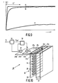
- Fig. 10 is a partly perspective view of a display device 18 in accordance with the invention, in this case it is provided with a flat cathode ray tube 19 having a rear plate 20, a glass front plate 21 which is provided on the inside with a pattern of phosphors 22, a system of selection electrodes 23 and a system of parallel line cathodes 24.
- These line cathodes 24 are connected at both ends to at least two electrically conductive connection means; in the present example all line cathodes are provided with connections 24 a up to and including 24 d .
- Deflection electrodes 25 are present between the line cathodes 24.
- the electrons emitted by the line cathodes 24 are deflected by deflection electrodes 25, they are selected by selection electrodes 23 and are incident on the phosphor pattern 22 at the location of front plate 21. An image is formed on the phosphor pattern by a suitable selection of the potentials at the deflection electrodes and selection electrodes.
- the connections 24 c and 24 d are connected to a voltmeter 27 by means of lines 25 c and 25 d .
- the reading of this voltmeter is compared with a reference voltage V ref in a comparison apparatus 28. This apparatus supplies a control signal to the current source 26.
- the drawing also schematically shows how a further improvement of the temperature control can be obtained.
- the line cathodes in a flat display tube are made so as to be as identical as possible. However, there is no certainty as to whether the resistance values are indeed indentical and will remain so during the life cycle of the tube. In order to reduce any differences in temperature occurring as a result hereof, the resistance of each line cathode is determined at room temperature.
- each line cathode is determined at room temperature.
- Dependent upon this V ref is determined for each line cathode in part 29. If, for example, the resistance at room temperature of three line cathodes is 95, 100 and 105 ⁇ , respectively, and the reference voltage drop corresponding to the desired temperature and the constant current intensity is 100 V for the line cathode having a resistance of 100 ⁇ , the reference voltage drop of the other line cathodes is 95 and 105 V, respectively. In this way, differences in temperature between the line cathodes are reduced.
Landscapes
- Control Of Indicators Other Than Cathode Ray Tubes (AREA)
- Electron Sources, Ion Sources (AREA)
- Details Of Television Scanning (AREA)
- Control Of Gas Discharge Display Tubes (AREA)
- Manufacture Of Electron Tubes, Discharge Lamp Vessels, Lead-In Wires, And The Like (AREA)
- Cathode-Ray Tubes And Fluorescent Screens For Display (AREA)
Abstract
Description
- The invention relates to an electron tube device comprising an electron tube having at least one line cathode, and an electric power source for the supply of power pulses to the line cathode.
- Such an electron tube device is known from United States Patent Specification 4,167,690, in which a description is given of a display device having a line cathode which is heated by means of power pulses. Between each consecutive pair of pulses there is an interval. During this interval an electron flow is extracted from the line cathode. This electron flow is modulated by a modulation system and an image is displayed on a display screen.
- It has been found that after such an electron tube device is switched on, relatively rapidly varying initial changes occur during the transient time in the number of electrons emitted per unit of time by the line cathode. Also during the life cycle of the electron tube device slowly varying temporal changes occur in the number of electrons emitted. In a display device these changes reveal themselves as changes in the intensity of the image displayed, which is undesired.
- It is an object of the invention to provide an electron tube device in which the changes in the number of electrons emitted per unit of time by the line cathode are reduced.
- To this end, an electron tube device of the type described in the opening paragraph is characterized in that the electron tube device comprises determination means for determining a value of a physical quantity depending on the temperature of the line cathode during a power pulse, comparison means for comparing the value with a reference value and for supplying a control signal, and termination means for ending the relevant power pulse in dependence on the control signal.
- It has been found that in an electron tube device in accordance with the invention the transient time and the temporal changes in the number of electrons emitted are reduced.
- The invention is based on the insight that the temperature of the line cathode does not only depend on the power supplied to the line cathode but also on the heat dissipated by the line cathode and other factors such as the mass of the line cathode.
- The line cathode dissipates heat by, inter alia, radiation and conduction. The amount of radiation heat depends, amongst others, on the temperatur, the emissivity and the size of the surface of the line cathode and the ambient temperature, i.e., the temperature of the surroundings on the line cathode. The amount of heat which is conducted away depends, inter alia, on the manner in which the line cathode is arranged in the electron tube, the temperature of the line cathode and the ambient temperature. If the power supplied remains constant, changes in, for example, the ambient temperature or the emissivity of the surface of the line cathode lead to changes in the temperature of the line cathode and, thus, to changes in the number of electrons emitted.
- In the prior-art method, the power supplied to the line cathode is constant. As a result hereof, the temperature of the line cathode is subject to changes during operation. Moreover, at a predetermined power supply the temperature of the line cathode cannot be accurately predicted.
- In an operational electron tub device in accordance with the invention, the value of a temperature-dependent physical quantity is determined during a power pulse, and the power pulse is ended if a comparison of this value with a reference value shows that the temperature of the line cathode exceeds a temperature which corresponds to the reference value.
- Thus, the power supplied to the line cathode depends on the value of the physical quantity and, hence, on the temperature of the line cathode, as a result of which an improved adjustment of the number of electrons emitted by the line cathode is achieved and the transient time, i.e. the time during which important intitial variations in the number of electrons emitted occur, is reduced.
- A preferred embodiment of the line-cathode arrangement in accordance with the invention is characterized in that the determination means can suitably be used for determining a physical quantity of the line cathode.
- In this case, the temperature of the line cathode is determined in a direct manner. The temperature of the line cathode can be determined indirectly, for example via the ambient temperature of the line cathode; the disadvantage of indirect temperature control relative to direct temperature determination is that both the possibility and the extent of the changes in the temperature of the line cathode are increased.
- Temperature-dependent properties of the line cathode may be, amongst others, the tensile load on the wire, the length of the wire, the electromagnetic radiation emitted, of which both the intensity and the frequency distribution are temperature-dependent, the number of electrons emitted per unit of time by the line cathode and the velocity distribution among these electrons, and the electrical resistance.
- A further embodiment of an electron tube device in accordance with the invention is characterized in that the determination means are at least partly present in the electron tube and are suitable for determining the number of electrons emitted per unit of time by the line cathode. During operation, the number of electrons emitted per unit of time is determined during a pulse and compared with a reference quantity; if the number is larger than the reference quantity the power pulse is ended. Thus, the number of electrons emitted per unit of time substantially corresponds to the desired number. This is a simple and direct manner of controlling the number of electrons emitted per unit of time. A disadvantage is that additional elements are accommodated in the electron tube, which are provided with connections. Consequently, the construction of the electron tube becomes more complicated and, moreover, there is a risk that the determination means or their connections may break. Since these means are present in the electron tube, it is difficult, or even impossible, to repair them.
- An alternative embodiment of an electron tube device in accordance with the invention is characterized in that the determination means comprise means for determining the resistance.
- This permits a simple way of controlling the temperature without the necessity of additional elements in the electron tube and with only a minimum number of additional connections being required.
- Yet a further embodiment of an electron tube device, in which the power source can suitably be used to apply a voltage drop across the line cathode within power pulses having a substantially constant current value, is characterized in that the means for determining the resistance comprise an arrangement for determining the voltage drop across the line cathode.
- This is a simple way of determining the resistance, which has little influence on the temperature of the line cathode.
- A further embodiment of an electron tube device in accordance with the invention is characterized in that the electron tube device comprises calibration means for determining a calibration value of the physical quantity, at a calibration temperature, and means for determining the reference value in dependence on the calibration value. If the calibration value has been determined at a known calibration temperature, the dependence of the physical quantity on the temperature is known. The reference value can be determined more accurately and compensated for changes in the calibration value during the life cycle of the electron tube device.
- The invention can advantageously be used, in particular, in an electron tube device in which the electron tube is provided with a system of line cathodes. In the case of electron tube devices having a number of line cathodes it is important that the number of electrons emitted per unit of time by the different line cathodes is equal to the extent possible so that there are no differences in intensity.
- This is important for, in particular, flat picture tubes.
- A few exemplary embodiments of the invention will now be described in more detail with reference to the drawing, in which
- Fig. 1 is a diagrammatic, sectional view of an electron tube device in accordance with the present state of the art;
- Fig. 2 is a diagrammatic sectional view of an electron tube device in accordance with the invention;
- Figs. 3, 4 and 5 are sectional views of further examples of electron tube devices in accordance with the invention;
- Fig. 6 graphically represents, as a function of time, the voltage drop across, the current through and the temperature of the line cathode for the known electron tube device if power pulses having a constant voltage drop value are supplied to the line cathode;
- Fig. 7 graphically represents, as a function of time, the voltage drop across, the current through and the temperature of the line cathode for the known electron tube device, if power pulses having a constant current value are supplied to the line cathode;
- Fig. 8 graphically represents, as a function of time, the voltage drop across, the current through and the temperature of the line cathode for the electron tube device in accordance with the invention, if power pulses having a constant current value are supplied to the line cathode;
- Fig. 9 graphically represents a comparison between the temperatures of a line cathode in an electron tube device known from the present state of the art and the temperature of a line cathode in an electron tube device in accordance with the invention;
- Fig. 10 is a partly perspective view of a further example of an electron tube device in accordance with the invention.
- The Figures are diagrammatic representations and are not drawn to scale, corresponding parts in the different embodiments generally bearing the same reference numerals.
- Fig. 1 shows an electron tube device known from the present state of the art. An
electron tube device 1 comprises anelectron tube 2 containing aline cathode 3, and apower source 4. Power pulses generated by thepower source 4 are supplied to theline cathode 3. The pulse duration is approximately 10µs, the interval, i.e. the time between the end of a power pulse and the beginning of the next power pulse is approximately 50µs. During the interval no voltage drop is applied across the line cathode. As has been described hereinbefore, the disadvantage of this known method is that the temperature of the line cathode cannot be accurately controlled and is subject to changes because the temperature does not only depend on the power supplied. A further disadvantage of the known state-of-the-art method is that if use is made of power pulses having a constant current value there is the risk of an excessive increase of the temperature of the line cathode. This disadvantage will be described hereinbelow by means of Fig. 7. - Fig. 2 shows an electron tube device in accordance with the invention. Power pulses generated by
power source 4 are supplied to theline cathode 3. During a power pulse the value of a physical quantity which depends on the temperature of the line cathode is determined by menas of a determination means 5. In a comparison means 6 the value is compared with a reference value G. A control signal T is generated by the comparison means 6 and is supplied to a termination means B. If the control signal indicates that the temperature of the line cathode exceeds a reference temperature corresponding to the reference value, the power pulse is ended, i.e. the voltage drop across theline cathode 3 is reduced to substantially nil. The termination means B may be contained in thepower source 4. - Fig. 3 is a diagrammatic view of an embodiment of an electron tube device in accordance with the invention. Determination means 5 comprise a
portion 5a in the electron tube. This portion is used to measure the number of electrons emitted per unit of time. In the comparison means 6 the number is compared with a reference number. If the number exceeds the reference number, the power pulse is ended. - Fig. 4 is an alternative embodiment of an electron tube device in accordance with the invention. Power pulses having a constant current are supplied to a
line cathode 7 by a current source 8. During a power pulse the voltage drop across the line cathode is measured by means of a voltmeter 9. This voltage drop is compared with a calibration value VG in a comparison means 10. The resistance changes as the temperature of the line cathode increases, in general the resistance will increase. The voltage drop across the line cathode increases. If the voltage drop exceeds the calibration value VG the current through the line cathode is reduced to nil by means of a control signal T, and the power pulse is ended. - Fig. 5 shows an alternative embodiment of the electron tube device in accordance with the invention. Power pulses having a constant voltage are applied to a
line cathode 11 by avoltage source 12. During a power pulse the current passing through the line cathode is measured by means of acurrent meter 13. This current is compared with a reference value IG in a comparison means 14. The resistance changes as the temperature of the line cathode increases, in general the resistance value will increase. The current passing through the line cathode will decrease. If this voltage drop becomes smaller than the reference value IG the voltage drop across the wire is reduced to nil by means of a control signal T. - Fig. 6 is a graphic representation, as a function of time, of the voltage drop across, the current passing through and the temperature of the line cathode for the known electron tube device, in which power pulses having a constant value of the voltage drop are supplied to the line cathode. The horizontal axis represents the time in arbitrary units, the vertical axis represents the voltage drop across the line cathode (V, represented by means of a continuous line), the current passing through the line cathode (I, represented by an interrupted line) and the temperature of the line cathode (T, represented by a chain line). During a power pulse duration t₁ a power pulse having a constant voltage is supplied to the line cathode. The temperature of the line cathode increases and, consequently, the resistance of the line cathode increases, and the current decreases. During the interval between two power pulses, t₂-t₁, no power is supplied to the line cathode and the temperature of the line cathode decreases. After a number of power pulses an equilibrium is established such that the average power supplied to the line cathode equals the heat dissipated by the line cathode. Both the power supplied and the dissipated heat depend themselves on the temperature of the line cathode. As the temperature of the line cathode increases, the average power supplied to the line cathode decreases, and the dissipated heat by the line cathode increases. The heat dissipated depends on the ambient temperature and on the thermal coupling between the line cathode and its environment. The temperature of the line cathode is stable only if the ambient temperature is stable. The time necessary to obtain a stable ambient temperture generally exceeds by far the warming-up time of a line cathode. Moreover, the thermal coupling between the line cathode and its environment may change during the life cycle of the line cathode. Moreover, in the case of a display device comprising more than one line cathode, the individual line cathodes have different ambient temperatures, even if the ambient temperature is stable for each line cathode, so that temperature differences between line cathodes occur and, hence, for example, differences in intensity in the image displayed are obtained.
- Fig. 7 is a graphic representation, as a function of time, of the voltage drop across, the current passing through and the temperature of the line cathode for the known electron tube device, power pulses having a constant current being supplied to the line cathode. On the horizontal and vertical axes the same quantities are plotted as in Fig. 6. United
States Patent Specification 4, 167, 690 advises against supplying power pulses having a constant current intensity to the line cathode because the power supply to the line cathode increases as the temperature of the line cathode increases and, consequently, the line cathode may be heated to an intolerably high temperature. - Fig. 8 is a graphic representation, as a function of time, of the voltage drop across, the current passing through and the temperature of the line cathode for the electron tube device in accordance with the invention, power pulses having a constant current intensity being supplied to the line cathode. On the horizontal and vertical axes the same quantities are plotted as in Figs. 6 and 7. Power pulses having a constant current intensity are supplied to the line cathode. During a power pulse the temperature of the line cathode increases, the resistance of the line cathode increases as a consequence thereof and, hence, the voltage drop across the line cathode increases. If this voltage drop exceeds a reference value VG the power supplied to the line cathode is reduced to nil. It has been found that in this way a quicker and more accurate temperature stabilization of the line cathode is obtained because the equilibrium temperture is independent of factors outside the line cathode.
- Fig. 9 graphically shows a comparison between the temperatures of a line cathode in an electron tube device in accordance with the present state of the art and the temperatures of a line cathode in an electron tube device in accordance with the invention. The time after the switching-on of the electron tube device is plotted on the horizontal axis and the temperature is plooted on the vertical axis. A
curve 15 shows the temperature of a line cathode in an electron tube device known from the present state of the art, acurve 16 shows a line cathode in an electron tube device in accordance with the invention. The temperature of a line cathode in an electron tube device in accordance with the invention rises very rapidly to the desired value, after which it remains substantially constant; during the transient time, t₁, the line cathode is warmed up very quickly. The temperature of a line cathode in an electron tube device in accordance with the present state of the art depends on the ambient temperature of the line cathode. This ambient temperature is represented by acurve 17. The temperature of the line cathode in a line cathode arrangement in accordance with the present state of the art initially rises just as quickly as in the case of the invention, but subsequently it rises slowly asymptotically, in a time t₁, to an equilibrium value. This equilibrium value is not known a priori, it will be different for different line cathodes and it depends on the ambient temperature. A change in the ambient temperature influences this equilibrium temperature. - Fig. 10 is a partly perspective view of a
display device 18 in accordance with the invention, in this case it is provided with a flatcathode ray tube 19 having arear plate 20, aglass front plate 21 which is provided on the inside with a pattern ofphosphors 22, a system ofselection electrodes 23 and a system ofparallel line cathodes 24. These line cathodes 24 are connected at both ends to at least two electrically conductive connection means; in the present example all line cathodes are provided withconnections 24a up to and including 24d. For the sake of clarity a part of the envelope has been left out.Deflection electrodes 25 are present between the line cathodes 24. The electrons emitted by the line cathodes 24 are deflected bydeflection electrodes 25, they are selected byselection electrodes 23 and are incident on thephosphor pattern 22 at the location offront plate 21. An image is formed on the phosphor pattern by a suitable selection of the potentials at the deflection electrodes and selection electrodes. The Figure schematically shows that theconnections current source 26 by means oflines 25a and 25b. Theconnections voltmeter 27 by means oflines comparison apparatus 28. This apparatus supplies a control signal to thecurrent source 26. The drawing also schematically shows how a further improvement of the temperature control can be obtained. The resistance of each line cathode is given by R(T) = F(T/TO)*R(TO), i.e., knowing the resistance at a known temperature, TO, suffices to find out the resistance at other temperatures. In general, the line cathodes in a flat display tube are made so as to be as identical as possible. However, there is no certainty as to whether the resistance values are indeed indentical and will remain so during the life cycle of the tube. In order to reduce any differences in temperature occurring as a result hereof, the resistance of each line cathode is determined at room temperature. This may be carried out, for example, by passing a very low current, which is equal for each line cathode, through each line cathode and measuring the voltage drop across each line cathode immediately after switching on the display device. In this way, the resistance of each line cathode is determined at room temperature. Dependent upon this Vref is determined for each line cathode inpart 29. If, for example, the resistance at room temperature of three line cathodes is 95, 100 and 105 Ω, respectively, and the reference voltage drop corresponding to the desired temperature and the constant current intensity is 100 V for the line cathode having a resistance of 100 Ω, the reference voltage drop of the other line cathodes is 95 and 105 V, respectively. In this way, differences in temperature between the line cathodes are reduced. - It will be clear that within the scope of the invention many variations are possible to those skilled in the art.
Claims (8)
Applications Claiming Priority (2)
| Application Number | Priority Date | Filing Date | Title |
|---|---|---|---|
| NL8801016A NL8801016A (en) | 1988-04-20 | 1988-04-20 | ELECTRON TUBE DEVICE AND ELECTRON TUBE. |
| NL8801016 | 1988-04-20 |
Publications (2)
| Publication Number | Publication Date |
|---|---|
| EP0339714A1 true EP0339714A1 (en) | 1989-11-02 |
| EP0339714B1 EP0339714B1 (en) | 1993-06-30 |
Family
ID=19852162
Family Applications (1)
| Application Number | Title | Priority Date | Filing Date |
|---|---|---|---|
| EP89200953A Expired - Lifetime EP0339714B1 (en) | 1988-04-20 | 1989-04-14 | Electron tube device and electron tube |
Country Status (6)
| Country | Link |
|---|---|
| US (1) | US5010275A (en) |
| EP (1) | EP0339714B1 (en) |
| JP (1) | JPH01313845A (en) |
| KR (1) | KR0132672B1 (en) |
| DE (1) | DE68907375T2 (en) |
| NL (1) | NL8801016A (en) |
Cited By (1)
| Publication number | Priority date | Publication date | Assignee | Title |
|---|---|---|---|---|
| EP2073242A2 (en) | 2007-12-21 | 2009-06-24 | Siemens Aktiengesellschaft | Tube, especially electron tube |
Families Citing this family (2)
| Publication number | Priority date | Publication date | Assignee | Title |
|---|---|---|---|---|
| US5608384A (en) * | 1992-10-23 | 1997-03-04 | Sentech Corporation | Method and apparatus for monitoring for the presence of a gas |
| DE19856384A1 (en) * | 1998-12-07 | 2000-06-08 | Siemens Ag | Method and circuit arrangement for regulating the operating point of a cathode ray tube |
Citations (3)
| Publication number | Priority date | Publication date | Assignee | Title |
|---|---|---|---|---|
| EP0075708A2 (en) * | 1981-09-30 | 1983-04-06 | Siemens Aktiengesellschaft | Direct heated cathode with filament heating control in electron beam equipments and method for operating the same |
| US4464611A (en) * | 1983-08-22 | 1984-08-07 | Rca Corporation | Line cathode heating and protection circuit |
| US4651058A (en) * | 1983-07-15 | 1987-03-17 | Matsushita Electric Industrial Co., Ltd. | Apparatus and method of operation for an electron beam source |
Family Cites Families (1)
| Publication number | Priority date | Publication date | Assignee | Title |
|---|---|---|---|---|
| US4167690A (en) * | 1977-05-02 | 1979-09-11 | Rca Corporation | Cathode and method of operating the same |
-
1988
- 1988-04-20 NL NL8801016A patent/NL8801016A/en not_active Application Discontinuation
-
1989
- 1989-04-13 US US07/337,241 patent/US5010275A/en not_active Expired - Fee Related
- 1989-04-14 DE DE89200953T patent/DE68907375T2/en not_active Expired - Fee Related
- 1989-04-14 EP EP89200953A patent/EP0339714B1/en not_active Expired - Lifetime
- 1989-04-18 KR KR1019890005041A patent/KR0132672B1/en not_active IP Right Cessation
- 1989-04-19 JP JP1097661A patent/JPH01313845A/en active Pending
Patent Citations (3)
| Publication number | Priority date | Publication date | Assignee | Title |
|---|---|---|---|---|
| EP0075708A2 (en) * | 1981-09-30 | 1983-04-06 | Siemens Aktiengesellschaft | Direct heated cathode with filament heating control in electron beam equipments and method for operating the same |
| US4651058A (en) * | 1983-07-15 | 1987-03-17 | Matsushita Electric Industrial Co., Ltd. | Apparatus and method of operation for an electron beam source |
| US4464611A (en) * | 1983-08-22 | 1984-08-07 | Rca Corporation | Line cathode heating and protection circuit |
Non-Patent Citations (1)
| Title |
|---|
| PATENT ABSTRACTS OF JAPAN, vol. 7, no. 222 (E-201)[1367], 4th October 1983; & JP-A-58 112 232 (FUJITSU K.K.) 04-07-1983 * |
Cited By (2)
| Publication number | Priority date | Publication date | Assignee | Title |
|---|---|---|---|---|
| EP2073242A2 (en) | 2007-12-21 | 2009-06-24 | Siemens Aktiengesellschaft | Tube, especially electron tube |
| DE102007062054A1 (en) | 2007-12-21 | 2009-07-02 | Siemens Ag | Tube, in particular electron tube |
Also Published As
| Publication number | Publication date |
|---|---|
| JPH01313845A (en) | 1989-12-19 |
| DE68907375D1 (en) | 1993-08-05 |
| US5010275A (en) | 1991-04-23 |
| KR900017066A (en) | 1990-11-15 |
| KR0132672B1 (en) | 1998-04-16 |
| EP0339714B1 (en) | 1993-06-30 |
| DE68907375T2 (en) | 1994-01-20 |
| NL8801016A (en) | 1989-11-16 |
Similar Documents
| Publication | Publication Date | Title |
|---|---|---|
| US6528958B2 (en) | Display device and cathode ray tube | |
| US7724248B2 (en) | Image display apparatus having deformation detection | |
| JP5318169B2 (en) | X-ray source and X-ray apparatus | |
| EP0339714B1 (en) | Electron tube device and electron tube | |
| JPS6236344B2 (en) | ||
| KR100261785B1 (en) | Field emission type display device and method for driving the same | |
| US20030057850A1 (en) | Method and apparatus for adjusting characteristics of multi electron source | |
| KR100276997B1 (en) | Auto stabilized cathode | |
| US2963608A (en) | Cathode ray tube structure | |
| US6048240A (en) | Method of manufacturing a cathode ray tube | |
| JP2006512865A (en) | A system that predicts and compensates for register changes and maintains white uniformity in the displayed image | |
| US3257848A (en) | Temperature transducers for very high temperature measuring systems | |
| KR910001508B1 (en) | Measuring method of electron emission for cathode ray tube | |
| EP0399713A2 (en) | Cathode ray tube display with increased cathode efficiency | |
| JP2001015060A (en) | Thermionic emission current control circit for gauge head of quadrupole mass spectrometer or hot cathode ionization gage | |
| KR100434525B1 (en) | Characteristic measuring system for field emission display device, including waveform generator, resistor, electron focusing unit, waveform detection unit and computation unit | |
| JP3165403B2 (en) | Control method of monitor automatic correction device | |
| US3465157A (en) | Temperature compensating circuits for photoelectric devices | |
| KR930004575B1 (en) | Emission characteristic testing method and its circuit of cathode-ray tube | |
| JPH11250845A (en) | Electron beam source | |
| US4631591A (en) | Kinescope with compensated conduction characteristic | |
| Sewell | General Guidelines for Operating ES-423E LaB6 Cathodes | |
| JP2002532926A (en) | Method and circuit device for adjusting operating point of cathode ray tube | |
| JP2722541B2 (en) | Image display device | |
| JPS6316850B2 (en) |
Legal Events
| Date | Code | Title | Description |
|---|---|---|---|
| PUAI | Public reference made under article 153(3) epc to a published international application that has entered the european phase |
Free format text: ORIGINAL CODE: 0009012 |
|
| AK | Designated contracting states |
Kind code of ref document: A1 Designated state(s): DE FR GB IT NL |
|
| 17P | Request for examination filed |
Effective date: 19900427 |
|
| 17Q | First examination report despatched |
Effective date: 19920205 |
|
| GRAA | (expected) grant |
Free format text: ORIGINAL CODE: 0009210 |
|
| AK | Designated contracting states |
Kind code of ref document: B1 Designated state(s): DE FR GB IT NL |
|
| PG25 | Lapsed in a contracting state [announced via postgrant information from national office to epo] |
Ref country code: IT Free format text: LAPSE BECAUSE OF FAILURE TO SUBMIT A TRANSLATION OF THE DESCRIPTION OR TO PAY THE FEE WITHIN THE PRESCRIBED TIME-LIMIT;WARNING: LAPSES OF ITALIAN PATENTS WITH EFFECTIVE DATE BEFORE 2007 MAY HAVE OCCURRED AT ANY TIME BEFORE 2007. THE CORRECT EFFECTIVE DATE MAY BE DIFFERENT FROM THE ONE RECORDED. Effective date: 19930630 Ref country code: NL Effective date: 19930630 |
|
| REF | Corresponds to: |
Ref document number: 68907375 Country of ref document: DE Date of ref document: 19930805 |
|
| ET | Fr: translation filed | ||
| NLV1 | Nl: lapsed or annulled due to failure to fulfill the requirements of art. 29p and 29m of the patents act | ||
| PLBE | No opposition filed within time limit |
Free format text: ORIGINAL CODE: 0009261 |
|
| STAA | Information on the status of an ep patent application or granted ep patent |
Free format text: STATUS: NO OPPOSITION FILED WITHIN TIME LIMIT |
|
| 26N | No opposition filed | ||
| REG | Reference to a national code |
Ref country code: FR Ref legal event code: CD |
|
| PGFP | Annual fee paid to national office [announced via postgrant information from national office to epo] |
Ref country code: GB Payment date: 19970401 Year of fee payment: 9 |
|
| PGFP | Annual fee paid to national office [announced via postgrant information from national office to epo] |
Ref country code: FR Payment date: 19970422 Year of fee payment: 9 |
|
| PGFP | Annual fee paid to national office [announced via postgrant information from national office to epo] |
Ref country code: DE Payment date: 19970624 Year of fee payment: 9 |
|
| PG25 | Lapsed in a contracting state [announced via postgrant information from national office to epo] |
Ref country code: GB Free format text: LAPSE BECAUSE OF NON-PAYMENT OF DUE FEES Effective date: 19980414 |
|
| PG25 | Lapsed in a contracting state [announced via postgrant information from national office to epo] |
Ref country code: FR Free format text: THE PATENT HAS BEEN ANNULLED BY A DECISION OF A NATIONAL AUTHORITY Effective date: 19980430 |
|
| GBPC | Gb: european patent ceased through non-payment of renewal fee |
Effective date: 19980414 |
|
| PG25 | Lapsed in a contracting state [announced via postgrant information from national office to epo] |
Ref country code: DE Free format text: LAPSE BECAUSE OF NON-PAYMENT OF DUE FEES Effective date: 19990202 |
|
| REG | Reference to a national code |
Ref country code: FR Ref legal event code: ST |