EP0339291A1 - Vertical shaft electric machine of the screen type - Google Patents
Vertical shaft electric machine of the screen type Download PDFInfo
- Publication number
- EP0339291A1 EP0339291A1 EP89105698A EP89105698A EP0339291A1 EP 0339291 A1 EP0339291 A1 EP 0339291A1 EP 89105698 A EP89105698 A EP 89105698A EP 89105698 A EP89105698 A EP 89105698A EP 0339291 A1 EP0339291 A1 EP 0339291A1
- Authority
- EP
- European Patent Office
- Prior art keywords
- bearing
- machine according
- rotor
- foundation
- truncated cone
- Prior art date
- Legal status (The legal status is an assumption and is not a legal conclusion. Google has not performed a legal analysis and makes no representation as to the accuracy of the status listed.)
- Granted
Links
Images

Classifications
-
- F—MECHANICAL ENGINEERING; LIGHTING; HEATING; WEAPONS; BLASTING
- F16—ENGINEERING ELEMENTS AND UNITS; GENERAL MEASURES FOR PRODUCING AND MAINTAINING EFFECTIVE FUNCTIONING OF MACHINES OR INSTALLATIONS; THERMAL INSULATION IN GENERAL
- F16C—SHAFTS; FLEXIBLE SHAFTS; ELEMENTS OR CRANKSHAFT MECHANISMS; ROTARY BODIES OTHER THAN GEARING ELEMENTS; BEARINGS
- F16C17/00—Sliding-contact bearings for exclusively rotary movement
- F16C17/12—Sliding-contact bearings for exclusively rotary movement characterised by features not related to the direction of the load
- F16C17/22—Sliding-contact bearings for exclusively rotary movement characterised by features not related to the direction of the load with arrangements compensating for thermal expansion
-
- F—MECHANICAL ENGINEERING; LIGHTING; HEATING; WEAPONS; BLASTING
- F16—ENGINEERING ELEMENTS AND UNITS; GENERAL MEASURES FOR PRODUCING AND MAINTAINING EFFECTIVE FUNCTIONING OF MACHINES OR INSTALLATIONS; THERMAL INSULATION IN GENERAL
- F16C—SHAFTS; FLEXIBLE SHAFTS; ELEMENTS OR CRANKSHAFT MECHANISMS; ROTARY BODIES OTHER THAN GEARING ELEMENTS; BEARINGS
- F16C35/00—Rigid support of bearing units; Housings, e.g. caps, covers
-
- H—ELECTRICITY
- H02—GENERATION; CONVERSION OR DISTRIBUTION OF ELECTRIC POWER
- H02K—DYNAMO-ELECTRIC MACHINES
- H02K1/00—Details of the magnetic circuit
- H02K1/06—Details of the magnetic circuit characterised by the shape, form or construction
- H02K1/22—Rotating parts of the magnetic circuit
- H02K1/28—Means for mounting or fastening rotating magnetic parts on to, or to, the rotor structures
- H02K1/30—Means for mounting or fastening rotating magnetic parts on to, or to, the rotor structures using intermediate parts, e.g. spiders
-
- H—ELECTRICITY
- H02—GENERATION; CONVERSION OR DISTRIBUTION OF ELECTRIC POWER
- H02K—DYNAMO-ELECTRIC MACHINES
- H02K5/00—Casings; Enclosures; Supports
- H02K5/04—Casings or enclosures characterised by the shape, form or construction thereof
- H02K5/16—Means for supporting bearings, e.g. insulating supports or means for fitting bearings in the bearing-shields
- H02K5/167—Means for supporting bearings, e.g. insulating supports or means for fitting bearings in the bearing-shields using sliding-contact or spherical cap bearings
-
- F—MECHANICAL ENGINEERING; LIGHTING; HEATING; WEAPONS; BLASTING
- F16—ENGINEERING ELEMENTS AND UNITS; GENERAL MEASURES FOR PRODUCING AND MAINTAINING EFFECTIVE FUNCTIONING OF MACHINES OR INSTALLATIONS; THERMAL INSULATION IN GENERAL
- F16C—SHAFTS; FLEXIBLE SHAFTS; ELEMENTS OR CRANKSHAFT MECHANISMS; ROTARY BODIES OTHER THAN GEARING ELEMENTS; BEARINGS
- F16C2380/00—Electrical apparatus
- F16C2380/26—Dynamo-electric machines or combinations therewith, e.g. electro-motors and generators
-
- Y—GENERAL TAGGING OF NEW TECHNOLOGICAL DEVELOPMENTS; GENERAL TAGGING OF CROSS-SECTIONAL TECHNOLOGIES SPANNING OVER SEVERAL SECTIONS OF THE IPC; TECHNICAL SUBJECTS COVERED BY FORMER USPC CROSS-REFERENCE ART COLLECTIONS [XRACs] AND DIGESTS
- Y10—TECHNICAL SUBJECTS COVERED BY FORMER USPC
- Y10S—TECHNICAL SUBJECTS COVERED BY FORMER USPC CROSS-REFERENCE ART COLLECTIONS [XRACs] AND DIGESTS
- Y10S384/00—Bearings
- Y10S384/90—Cooling or heating
- Y10S384/905—Temperature compensation
Definitions
- the invention relates to a vertical-axis electrical machine in a screen design, in particular a hydrogen generator, with a stator attached to a foundation or in a foundation pit and supported there against the pit wall and an essentially disk-shaped rotor with a combined support and guide bearing, which is also on a is supported on the foundation supported bearing support structure.
- Generators for drive by Kaplan turbines - more rarely for Francis, sometimes also for propeller turbines - are often designed as so-called shield types, in which the rotor sits on the shaft on the fly - i.e. without an upper neck bearing (see loc. Cit., P. 167, Fig. 54 or p. 169, Fig. 56).
- the support bearing is combined with the lower neck bearing and in the lower Support star installed.
- the support star is supported on the foundation.
- the invention has for its object to provide a vertical-axis electrical machine in shield design, which has a structurally simple bearing construction and in which the centering of the rotor relative to the stator is maintained in all operating states.
- the bearing support structure is essentially designed as a hollow truncated cone, the lower end of the hollow truncated cone, which has a larger diameter, is supported directly on the foundation and anchored there, and at the other (upper end) of the Hollow truncated cone the combined support and guide bearing is arranged.
- Such a structure can be implemented in a simple manner as a sheet metal / welded construction.
- auxiliary units such as the oil cooler and oil pump in addition to the shaft leading to the hydropower machine.
- the truncated cone jacket acts like an inclined spoke arrangement with axial inclined arms:
- the rotor is preferably designed as a flat disc, the flywheel, e.g. in the form of rings or sheet segments.
- the rotor poles are fastened to these rotor rings in the usual way.
- radial stiffening ribs are preferably provided, which have an axially increasing axial height for longer iron lengths. Their height - and thus their stiffening effect - is only limited by the truncated cone. In addition to stiffening, they also serve as rotor ventilation.
- the rotor is supported directly on the bearing.
- a hub in the usual sense no longer exists.
- this can also be designed in the form of a truncated cone.
- the combination of a flat disc with such a truncated cone is also possible.
- Such a construction without a hub makes it possible for the first time to place the support and guide bearing axially seen in the middle of the iron length or the poles of a flat disc rotor, so that the lever arm between the force application point of the rotor mass and the guide bearing becomes zero.
- the invention enables a significant simplification of the construction and its calculation and a reduction in the construction volume.
- the generator group and crane height are reduced, the whole nacelle gets lower.
- the foundations are simpler because of the even load; no or only very small machine parts have to be concreted in.
- the largest transport weights (rotor hub, support bearing central body) are reduced.
- the rotor 4 consists of a flat disc 5, which can be welded together from a plurality of plates in the case of larger rotor diameters.
- a plurality of rings 9 or ring segments are fastened from below in the edge region of the disk 5. Together with the poles 10 arranged on the outer circumference of the disk 5 or rings 9, these form the flywheel.
- the shaft leading to the hydropower plant is flanged in the center of the disk.
- the combined support and guide bearing generally designated by the reference number 12, has a rotating bearing part 13 which is fastened directly to the disk 5 and which is coaxial with the shaft 11.
- the stationary bearing part 14 is fastened directly on a bearing support structure supported on the foundation 1.
- the support and guide segments 15 rest in the machine longitudinal direction on support stamps 16. In the example, the segments 15 have an L-shaped cross section.
- a self-pumping hydrodynamic plain bearing is preferably used, as described in detail in, for example, CH-PS 651 362 or US Pat. No. 4,573,810, and the proviso that the supporting bearing segment and guide bearing segment are preferably made in one piece.
- the bearing structure consists of a hollow truncated cone 17 and a cone shell angle between 30 ° and 60 ° and is made of pre-bent steel sheets that are welded or screwed together on the construction site.
- a cover ring 18 is welded or welded onto which the stationary bearing part 14 is fastened.
- the Truncated cone attached to the foundation 1 by means of foundation tankers 19.
- a number of radial stiffening ribs 20 corresponding to the number of poles are fastened both to the disk 5 and to the rings 9 or segments. In addition to stiffening the rotor, they also serve to convey cooling air to the poles, radial cooling air slots or bores being provided in the rings 9 or segments.
- the fixed part 21 of the braking device which cooperates with a brake ring 22 on the underside of the ring stack 9, is also supported on the bearing support structure 17.
- the slip ring apparatus 23 of the generator is also shown in FIG. 1, the rotating part 24 of which can be flanged onto the top of the disk 5 in a space-saving manner.
- the foundation pit is covered by a cover plate 26 provided with an assembly and service opening 25.
- Fig. 1 the reduction in height achievable by the invention is very clearly visible.
- the space in the interior of the truncated cone 17 can even be used to accommodate additional units, in particular the oil cooler 27 and possibly oil pumps in the bearing.
- the stator is arranged concentrically in the foundation pit 1.
- the stator sheet metal body 3 no longer has a housing in the usual sense and is supported against the foundation wall 2 by means of oblique spokes 28.
- Such a support is known per se and is the subject of DE-PS 2 459 237 or US-PS 4,060,744.
- axially running dovetail shapes are on the outer circumference of the laminated core Mige grooves 29 are provided, in which strips 30 are created with double dovetail cross-section.
- strips 32 with double dovetail cross-section are fastened on plates anchored in the wall 2.
- the inclined spokes 28 are connected in pairs via webs 33. Radially inside and outside, the webs 33 have dovetail-shaped recesses 34 which interact with the strips 30 and 32.
- the strips 30 and 32 are each positively suspended in the grooves 29 or recesses 34 and e.g. welded. This process takes place after the stator 3 has been aligned in the foundation pit 1, centering aids 35 being used which are successively replaced by pairs of oblique spokes.
- pairs of inclined spokes or their inner webs 33 each comprise at least one butt joint of the laminated core stacked from sheet metal segments 36.
- the inclined spokes - the optimal angle ⁇ is between 30 ° and 50 ° - temperature-related expansions of the stator are converted into a relative rotation between stator 3 and foundation 1.
- the torque is also transmitted from the stator laminated core to the foundation through the bevel spokes.
- the rotor center part 6 is designed as a truncated cone, which is welded in the hub area with a ring 7 fastened on the rotating bearing part 13.
- the rotor center part 6 is welded to the outer circumference with an outer ring 8, which takes over the function of a flywheel and pole support device for the rotor poles 10.
- An opening 38 in the rotor center part 6, which can be closed with a cover 37, enables access to the combined support and guide bearing 12, here instead of an L-shaped one Support and guide segments separate support and guide segments 15a and 15b are used.
- the rotor 40 of the exciter 25 is flanged onto the rotating bearing part 13. Trusses 39 serve to suspend the stator 41 of the excitation machine 25.
- radial stiffening ribs 20a can be provided, which are welded to both the central rotor part 6 and the outer ring 8.
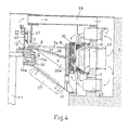
- FIG. 4 For the sake of completeness, the ventilation of the rotor / stator is shown in FIG. 4.
- openings 42, 43, 44 through which cooling air alternately flows in and out. is dissipated, attached.
Landscapes
- Engineering & Computer Science (AREA)
- General Engineering & Computer Science (AREA)
- Power Engineering (AREA)
- Mechanical Engineering (AREA)
- Motor Or Generator Frames (AREA)
- Connection Of Motors, Electrical Generators, Mechanical Devices, And The Like (AREA)
- Paper (AREA)
- Electrochromic Elements, Electrophoresis, Or Variable Reflection Or Absorption Elements (AREA)
- Overhead Projectors And Projection Screens (AREA)
- Manufacture Of Motors, Generators (AREA)
- Support Of The Bearing (AREA)
- Synchronous Machinery (AREA)
- Shielding Devices Or Components To Electric Or Magnetic Fields (AREA)
Abstract
Description
Die Erfindung bezieht sich auf eine vertikalachsige elektrische Maschine in Schirmbauweise, insbesondere Hydrogenerator, mit einem auf einem Fundament befestigten oder in einer Fundamentgrube und dort gegen die Grubenwand abgestützten Stator und einem in wesentlichen scheibenförmigen Rotor mit einem kombinierten Trag- und Führungslager, welches auf einer gleichfalls auf dem Fundament abgestützten Lagertragkonstruktion befestigt ist.The invention relates to a vertical-axis electrical machine in a screen design, in particular a hydrogen generator, with a stator attached to a foundation or in a foundation pit and supported there against the pit wall and an essentially disk-shaped rotor with a combined support and guide bearing, which is also on a is supported on the foundation supported bearing support structure.
Eine derartige elektrische Maschine ist beispielsweise aus dem Buch von Wiedemann-Kellerberger "Konstruktion elektrischer Maschinen" Springer Verlag, Berlin-Heidelberg-New York 1967, S. 169, Abb, 56, bekannt.Such an electrical machine is known, for example, from the book by Wiedemann-Kellerberger "Construction of Electrical Machines" Springer Verlag, Berlin-Heidelberg-New York 1967, p. 169, fig. 56.
Generatoren für Antrieb durch Kaplanturbinen - seltener für Francis-, manchmal auch für Propellerturbinen - werden vielfach als sogenannte Schirmtypen ausgeführt, bei welchen der Rotor fliegend - also ohne oberes Halslager - auf der Welle sitzt (vgl. a.a.O., S. 167, Abb. 54 oder S. 169, Abb. 56). Das Traglager ist mit dem unteren Halslager kombiniert und im unteren Tragstern eingebaut. Der Tragstern stützt sich auf dem Fundament ab.Generators for drive by Kaplan turbines - more rarely for Francis, sometimes also for propeller turbines - are often designed as so-called shield types, in which the rotor sits on the shaft on the fly - i.e. without an upper neck bearing (see loc. Cit., P. 167, Fig. 54 or p. 169, Fig. 56). The support bearing is combined with the lower neck bearing and in the lower Support star installed. The support star is supported on the foundation.
Weil das Trag- und Führungslager und der zentrale Bereich der Lagertragkonstruktion trotz intensiver Kühlung (durch das Schmiermittel) eine wesentlich höhere Temperatur annehmen als die peripheren Teile der Lagertragkonstruktion, entstehen mechanische Spannungen, die bei starren Lagertraganordnungen auf das Fundament übertragen werden müssen.Because the support and guide bearing and the central area of the bearing support structure, despite intensive cooling (by the lubricant), reach a significantly higher temperature than the peripheral parts of the bearing support structure, mechanical stresses arise which have to be transferred to the foundation in the case of rigid bearing support arrangements.
Eine Möglichkeit, derartige Belastungen vom Fundament fernzuhalten besteht darin, den Tragstern mit Schrägarmen bzw. Schrägspeichen zu versehen. Auf diese Weise werden unter Beibehaltung der Zentrierung und nur unwesentlicher Verkleinerung der radialen Steifigkeit Dehnungen der zentralen Bauteile in eine relative Drehung zwischen besagten Bauteilen und dem Fundament umgesetzt (vgl. DE-PS 2 495 236 oder US-PS 4,258,280). Die Schrägspeicherlösung erfordert jedoch eine aufwendige Stahlkonstruktion mit beträchtlich grosser axialer Höhe und ist für Schirmgeneratoren nur bedingt anwendbar.One way of keeping such loads away from the foundation is to provide the support star with inclined arms or inclined spokes. In this way, while maintaining the centering and only insignificantly reducing the radial rigidity, expansions of the central components are converted into a relative rotation between said components and the foundation (cf. DE-PS 2 495 236 or US-PS 4,258,280). The inclined storage solution, however, requires a complex steel construction with a considerably large axial height and can only be used to a limited extent for screen generators.
Ausgehend vom Stand der Technik liegt der Erfindung die Aufgabe zugrunde, eine vertikalachsige elektrische Maschine in Schirmbauweise zu schaffen, die eine konstruktiv einfache Lagerkonstruktion aufweist und bei welcher die Zentrierung des Rotors gegenüber dem Stator in allen Betriebszuständen erhalten bleibt.Starting from the prior art, the invention has for its object to provide a vertical-axis electrical machine in shield design, which has a structurally simple bearing construction and in which the centering of the rotor relative to the stator is maintained in all operating states.
Diese Aufgabe wird erfindungsgemäss dadurch gelöst, dass die Lagertragkonstruktion in wesentlichen als Hohlkegelstumpf ausgebildet ist, das untere, den grösseren Durchmesser aufweisende Ende des Hohlkegelstumpfes unmittelbar auf dem Fundament abgestützt und dort verankert ist, und am anderen (oberen Ende) des Hohlkegelstumpfes das kombinierte Trag- und Führungslager angeordnet ist.This object is achieved in that the bearing support structure is essentially designed as a hollow truncated cone, the lower end of the hollow truncated cone, which has a larger diameter, is supported directly on the foundation and anchored there, and at the other (upper end) of the Hollow truncated cone the combined support and guide bearing is arranged.
Ein derartiger Aufbau ist in einfacher Weise als Blech/Schweisskonstruktion zu realisieren. Im Innern des Kegelstumpfes finden neben der zur Wasserkraftmaschine führenden Welle Nebenaggregate wie Oelkühler und Oelpumpe Platz.Such a structure can be implemented in a simple manner as a sheet metal / welded construction. In the interior of the truncated cone there is space for auxiliary units such as the oil cooler and oil pump in addition to the shaft leading to the hydropower machine.
Der Kegelstumpfmantel wirkt im weitesten Sinne wie eine Schrägspeichenanordnung mit Axial-Schrägarmen:In the broadest sense, the truncated cone jacket acts like an inclined spoke arrangement with axial inclined arms:
Bei Erwärmung des Lagers und der daran angrenzenden zentralen Teile der Tragkonstruktion bleibt die gegenseitige Zentrierung von Rotor und Stator erhalten. Thermisch bedingte Dehnungen werden in eine axiale Verlängerung des Kegelstumpfes umgesetzt, die radiale Steifigkeit bleibt erhalten.When the bearing and the central parts of the supporting structure adjacent to it are heated, the mutual centering of the rotor and stator is retained. Thermally induced strains are converted into an axial extension of the truncated cone, the radial rigidity is retained.
Der Rotor ist vorzugsweise als ebene Scheibe ausgebildet, die an ihrem Aussenumfang Schwungmasse, z.B. in Form von Ringen oder Blechsegmenten, trägt. An diesen Rotorringen sind die Rotorpole in üblicher Weise befestigt. Zur Versteifung des Rotors in Axialrichtung sind vorzugsweise radiale Versteifungsrippen vorgesehen, die bei grösseren Eisenlängen eine nach aussen zunehmende axiale Höhe aufweisen. Ihre Höhe - und damit ihre versteifende Wirkung-ist nur durch den Kegelstumpfmantel begrenzt. Neben der Versteifung dienen sie gleichzeitig der Rotorventilation.The rotor is preferably designed as a flat disc, the flywheel, e.g. in the form of rings or sheet segments. The rotor poles are fastened to these rotor rings in the usual way. For stiffening the rotor in the axial direction, radial stiffening ribs are preferably provided, which have an axially increasing axial height for longer iron lengths. Their height - and thus their stiffening effect - is only limited by the truncated cone. In addition to stiffening, they also serve as rotor ventilation.
Der Rotor stützt sich dabei unmittelbar auf dem Lager ab. Eine Nabe im üblichen Sinn existiert nicht mehr.The rotor is supported directly on the bearing. A hub in the usual sense no longer exists.
Anstelle eines scheibenförmigen Rotors kann dieser auch in Form eines Hohlkegelstumpfes ausgebildet sein. Auch ist die Kombination einer ebenen Scheibe mit einem derartigen Hohlkegelstumpf möglich.Instead of a disc-shaped rotor, this can also be designed in the form of a truncated cone. The combination of a flat disc with such a truncated cone is also possible.
Eine derartige Konstruktion ohne Nabe ermöglicht es erstmals, bei einem ebenen Scheibenrotor das Trag- und Führungslager axial gesehen in die Mitte der Eisenlänge bzw. der Pole zu legen, so dass der Hebelarm zwischen dem Kraftangriffspunkt der Rotormasse und dem Führungslager zu Null wird.Such a construction without a hub makes it possible for the first time to place the support and guide bearing axially seen in the middle of the iron length or the poles of a flat disc rotor, so that the lever arm between the force application point of the rotor mass and the guide bearing becomes zero.
Die Erfindung ermöglicht bei gleicher Einheitsleistung neben einer wesentlichen Vereinfachung der Konstruktion und deren Berechnung eine Verkleinerung des Bauvolumens. Die Generatorgruppe und Kranhöhe sind reduziert, das ganze Maschinenhaus wird niedriger. Die Fundamente sind wegen der gleichmässigen Belastung einfacher; es müssen keine oder nur sehr kleine Maschinenteile einbetoniert werden. Die grössten Transportgewichte (Rotornabe, Traglager-Zentralkörper) sind reduziert.With the same unit output, the invention enables a significant simplification of the construction and its calculation and a reduction in the construction volume. The generator group and crane height are reduced, the whole nacelle gets lower. The foundations are simpler because of the even load; no or only very small machine parts have to be concreted in. The largest transport weights (rotor hub, support bearing central body) are reduced.
In der Zeichnung ist ein Ausführungsbeispiel des Erfindungsgegenstandes z.T. stark schematisiert dargestellt; dabei zeigt
- Fig. 1 einen Längsschnitt durch einen Schirmgenerator;
- Fig. 2 eine Draufsicht, teilweise im Schnitt auf den Schirmgenerator;
- Fig. 3 einen vergrösserten Ausschnitt aus Fig. 2, aus dem die unmittelbare Abstützuung des Stators an der Wand der Fundamentgruppe hervorgeht;
- Fig. 4 eine Ausführungsform eines Schirmgenerators mit einem hohlkegelstumpfförmigen Rotor.
- 1 shows a longitudinal section through a screen generator.
- Figure 2 is a plan view, partly in section, of the screen generator;
- 3 shows an enlarged detail from FIG. 2, from which the stator is supported directly on the wall of the foundation group;
- Fig. 4 shows an embodiment of a screen generator with a hollow truncated cone-shaped rotor.
Der Schirmgenerator nach Fig. 1 ist in einer Fundamentgruppe 1 mit kreiszylindrischer Wand 2 eingebettet. Sein Stator 3 ist über Abstützelemente 4, deren Aufbau später anhand von Fig. 3 erläutert wird, ohne eigentliches Statorgehäuse an der Wand 2 abgestützt. Der Rotor 4 besteht aus einer ebenen Scheibe 5, die bei grösseren Rotordurchmessern aus mehreren Platten zusammengeschweisst sein kann. Im Randbereich der Scheibe 5 sind von unten eine Mehrzahl von Ringen 9 oder Ringsegmenten befestigt. Diese bilden zusammen mit den am Aussenumfang der Scheibe 5 bzw. Ringe 9 angeordneten Pole 10 die Schwungmasse. Im Zentrum der Scheibe ist die zur Wasserkraftmaschine führende Welle angeflanscht.1 is embedded in a foundation group 1 with a circular
Das generell mit der Bezugsziffer 12 bezeichnete kombinierte Trag- und Führungslager weist einen rotierenden, unmittelbar an der Scheibe 5 befestigten Lagerteil 13 auf, welcher koaxial zur Welle 11 liegt. Der stationäre Lagerteil 14 ist unmittelbar auf einer auf dem Fundament 1 abgestützten Lagertragkonstruktion befestigt. Die Trag- und Führungssegemente 15 ruhen in Maschinenlängsrichtung auf Tragstempeln 16. Im Beispielsfall weisen die Segmente 15 L-förmigen Querschnitt auf.The combined support and guide bearing, generally designated by the
Vorzugsweise findet ein selbstpumpendes hydrodynamisches Gleitlager Verwendung, wie es beispielsweise in der CH-PS 651 362 oder der US-PS 4,573,810 in allen Einzelheiten beschrieben ist, und der Massgabe, dass vorzugsweise Traglagersegment und Führungslagersegment einstückig ausgeführt sind.A self-pumping hydrodynamic plain bearing is preferably used, as described in detail in, for example, CH-PS 651 362 or US Pat. No. 4,573,810, and the proviso that the supporting bearing segment and guide bearing segment are preferably made in one piece.
Die Lagerkonstruktion besteht aus einem hohlen Kegelstumpf 17 und einem Kegelmantelwinkel zwischen 30° und 60° und ist aus entsprechend vorgebogenen Stahlblechen, die auf der Baustelle zusammengeschweisst- oder geschraubt werden. Am oberen Ende ist ein Abdeckring 18 an- bzw. eingeschweisst, auf dem der stationäre Lagerteil 14 befestigt ist. Am anderen Ende ist der Kegelstumpf mittels Fundamenttankern 19 am Fundament 1 befestigt.The bearing structure consists of a hollow truncated
Zur Versteifung der Rotorkonstruktion sind eine der Anzahl Pole entsprechende Zahl von radialen Versteifungsrippen 20 sowohl an der Scheibe 5 als auch an den Ringen 9 oder Segmenten befestigt. Neben der Versteifung des Rotors dienen sie gleichzeitig zur Kühlluftförderung zu den Polen, wobei in den Ringen 9 oder Segmenten radiale Kühlluftschlitze oder -bohrungen vorgesehen sind.To stiffen the rotor construction, a number of radial
An der Lagertragkonstruktion 17 ist auch der feststehende Teil 21 der Bremsvorrichtung abgestützt, die mit einem Bremsring 22 an der Unterseite des Ringstapels 9 zusammenwirkt.The
Aus Gründen der Vollständigkeit ist in Fig. 1 auch der Schleifringapparat 23 des Generators eingezeichnet, dessen rotierender Teil 24 in platzsparender Weise auf der Oberseite der Scheibe 5 angeflanscht werden kann.For the sake of completeness, the
Die Fundamentgrube ist durch eine mit einer Montage- und Serviceöffnung 25 versehene Abdeckplatte 26 abgedeckt.The foundation pit is covered by a
In Fig. 1 ist die durch die Erfindung erzielbare Reduktion der Bauhöhe sehr gut sichtbar. Der im Innenraum des Kegelstumpfes 17 vorhandene Raum kann sogar zur Unterbringung von Zusatzaggregaten, insbesondere der Oelkühler 27 und eventuell Oelpumpen des Lagers genutzt werden.In Fig. 1 the reduction in height achievable by the invention is very clearly visible. The space in the interior of the
Der Stator ist, wie aus Fig. 2 zu erkennen ist, konzentrisch in der Fundamentgrube 1 angeordnet. Der Statorblechkörper 3 weist kein Gehäuse im üblichen Sinn mehr auf und ist über Schrägspeichen 28 gegenüber der Fundamentwand 2 abgestützt. Eine derartige Abstützung ist an sich bekannt und Gegenstand der DE-PS 2 459 237 oder der US-PS 4,060,744. Zu diesem Zweck sind am Blechpaket-Aussenumfang axial verlaufende schwalbenschwanzför mige Nuten 29 vorgesehen, in welche Leisten 30 mit doppelschwalbenschwanzförmigem Querschnitt angelegt sind.As can be seen from FIG. 2, the stator is arranged concentrically in the foundation pit 1. The stator
An der Wand 2 sind auf in der Wand 2 verankerten Platten 31 Leisten 32 mit doppelschwalbenschwanzförmigem Querschnitt befestigt. Die Schrägspeichen 28 sind paarweise über Stege 33 verbunden. Radial innen und aussen weisen die Stege 33 schwalbenschwanzförmige Ausnehmungen 34 auf, welche mit den Leisten 30 und 32 zusammenwirken.On the
Die Leisten 30 und 32 sind jeweils in den Nuten 29 bzw. Ausnehmungen 34 formschlüssig eingehängt und z.B. verschweisst. Dieser Vorgang erfolgt nach Ausrichten des Stators 3 in der Fundamentgrube 1, wobei Zentrierhilfen 35 Verwendung finden, die nacheinander durch Schrägspeichenpaare ersetzt werden.The
Aus Fig. 3 ist ferner zu entnehmen, dass die Schrägspeichenpaare bzw. deren innere Stege 33 jeweils mindestens eine Stossstelle des aus Blechsegmenten 36 geschichteten Blechpakets umfassen.From FIG. 3 it can also be seen that the pairs of inclined spokes or their
Durch die Schrägspeichen - der optimale Winkel α liegt zwischen 30° und 50° - werden temperaturbedingte Dehnungen des Stators in eine relative Drehung zwischen Stator 3 und Fundament 1 umgesetzt. Durch die Schrägspeichen wird ebenfalls das Drehmoment vom Statorblechpaket auf das Fundament übertragen.The inclined spokes - the optimal angle α is between 30 ° and 50 ° - temperature-related expansions of the stator are converted into a relative rotation between
In der Ausführungsform nach Fig. 4 ist der Rotormittelteil 6 als Hohlkegelstumpf ausgebildet, der im Nabenbereich mit einem auf dem rotierenden Lagerteil 13 befestigten Ring 7 angeschweisst ist. Am Aussenumfang ist der Rotormittelteil 6 mit einem Aussenring 8 verschweisst, welcher die Funktion einer Schwungmasse und Poltrageinrichtung für die Rotorpole 10 übernimmt. Eine mit einer Abdeckung 37 verschliessbare Oeffnung 38 im Rotormittelteil 6 ermöglicht den Zugang zum kombinierten Trag- und Führungslager 12, wobei hier anstelle L-förmiger Trag- und Führungssegmente getrennte Trag- und Führungssegmente 15a bzw. 15b Verwendung finden.In the embodiment according to FIG. 4, the
Wie im ersten Ausführungsbeispiel ist auch hier der Rotor 40 der Erregermaschine 25 am rotierenden Lagerteil 13 angeflanscht. Traversen 39 dienen zur Aufhängung des Stators 41 der Erregermaschine 25. Auch hier können radiale Versteifungsrippen 20a vorgesehen sein, welche sowohl mit dem Rotormittelteil 6 als auch mit dem Aussenring 8 verschweisst sind.As in the first exemplary embodiment, the
Der Vollständigkeit halber ist in Fig. 4 die Belüftung des Rotors/Stators eingezeichnet. In der Wand 2 des Fundaments 1 sind Durchbrüche 42,43,44, durch welche abwechselnd Kühlluft zu- bwz. abgeführt wird, angebracht.For the sake of completeness, the ventilation of the rotor / stator is shown in FIG. 4. In the
In Fig. 4 ist schlussendlich strichliert die Kombination einer ebenen Scheibe 5a mit einem hohlkegelstumpfförmigen Rotormittelteil angedeutet, die auch dem erfindungsgemässen Lösungsgedanken folgt.4, the combination of a
Claims (11)
Priority Applications (1)
| Application Number | Priority Date | Filing Date | Title |
|---|---|---|---|
| AT89105698T ATE93101T1 (en) | 1988-04-26 | 1989-03-31 | VERTICAL AXIS ELECTRIC MACHINE IN SCREEN CONSTRUCTION. |
Applications Claiming Priority (2)
| Application Number | Priority Date | Filing Date | Title |
|---|---|---|---|
| CH1556/88 | 1988-04-26 | ||
| CH1556/88A CH675800A5 (en) | 1988-04-26 | 1988-04-26 |
Publications (2)
| Publication Number | Publication Date |
|---|---|
| EP0339291A1 true EP0339291A1 (en) | 1989-11-02 |
| EP0339291B1 EP0339291B1 (en) | 1993-08-11 |
Family
ID=4213178
Family Applications (1)
| Application Number | Title | Priority Date | Filing Date |
|---|---|---|---|
| EP89105698A Expired - Lifetime EP0339291B1 (en) | 1988-04-26 | 1989-03-31 | Vertical shaft electric machine of the screen type |
Country Status (12)
| Country | Link |
|---|---|
| US (1) | US4922150A (en) |
| EP (1) | EP0339291B1 (en) |
| JP (1) | JPH01318531A (en) |
| CN (1) | CN1017012B (en) |
| AT (1) | ATE93101T1 (en) |
| BR (1) | BR8901950A (en) |
| CA (1) | CA1307020C (en) |
| CH (1) | CH675800A5 (en) |
| DE (1) | DE58905210D1 (en) |
| ES (1) | ES2043927T3 (en) |
| IN (1) | IN171940B (en) |
| NO (1) | NO891429L (en) |
Cited By (2)
| Publication number | Priority date | Publication date | Assignee | Title |
|---|---|---|---|---|
| EP0439739A1 (en) * | 1990-01-30 | 1991-08-07 | Asea Brown Boveri Ag | Synchronous electric machine |
| EP4296502A1 (en) * | 2022-06-24 | 2023-12-27 | GE Renewable Technologies | Stator frame foot |
Citations (10)
| Publication number | Priority date | Publication date | Assignee | Title |
|---|---|---|---|---|
| DE416740C (en) * | 1924-02-21 | 1925-07-23 | Bullinger Werke Bullinger & Co | Storage of shafts and machine parts in thin-walled, cylindrical housings, especially of small electrical machines |
| US1687513A (en) * | 1928-01-13 | 1928-10-16 | Gen Electric | Rotor |
| DE889319C (en) * | 1950-04-21 | 1953-09-10 | Escher Wyss Maschinenfabrik G | Electrical machine with vertical shaft that can be used as a generator or motor |
| DE962911C (en) * | 1953-09-12 | 1957-05-02 | Neyrpic Ets | Hydropower generator with vertical axis in which the generator shaft has a hollow hub shape |
| DE969451C (en) * | 1954-06-15 | 1958-06-04 | Westinghouse Canada Ltd | Oil pot for thrust bearing |
| FR1171936A (en) * | 1955-03-25 | 1959-02-03 | Neyrpic Ets | Stop mounting device in a hydro-electric unit |
| FR1189531A (en) * | 1957-01-08 | 1959-10-05 | Zd Y Jiriho Dimitrova Narodni | Bearing suspension device, in particular of a turbo-generator |
| DE1947043A1 (en) * | 1969-09-12 | 1971-03-18 | Siemens Ag | Vertical, especially electrical, machine |
| US3806211A (en) * | 1972-07-26 | 1974-04-23 | Hitachi Ltd | Thrust support means for vertical shaft type rotary machine |
| FR2292365A1 (en) * | 1974-11-19 | 1976-06-18 | Bbc Brown Boveri & Cie | VERTICAL AXIS ELECTRIC MACHINE |
Family Cites Families (12)
| Publication number | Priority date | Publication date | Assignee | Title |
|---|---|---|---|---|
| US1714484A (en) * | 1922-11-27 | 1929-05-21 | Us Industries Inc | Turbine pump |
| DE966540C (en) * | 1939-04-18 | 1957-08-22 | Aeg | Pole wheel attachment for hydropower generators in shield design |
| US2701171A (en) * | 1951-12-17 | 1955-02-01 | Allis Chalmers Mfg Co | Vertical flanged shaft and thrust bearing removable together from bearing support |
| US3271607A (en) * | 1963-08-15 | 1966-09-06 | Westinghouse Electric Corp | Waterwheel dynamoelectric machine rotor |
| JPS50134109A (en) * | 1974-04-17 | 1975-10-24 | ||
| CH578708A5 (en) * | 1974-11-19 | 1976-08-13 | Bbc Brown Boveri & Cie | |
| US4048528A (en) * | 1975-10-14 | 1977-09-13 | Westinghouse Electric Corporation | Starting motor for large inertia load |
| US4258280A (en) * | 1975-11-07 | 1981-03-24 | Bbc Brown Boveri & Company Limited | Supporting structure for slow speed large diameter electrical machines |
| JPS54157204A (en) * | 1978-06-01 | 1979-12-12 | Hitachi Ltd | Stator for vertical rotoary shaft electric machine |
| JPS5831755B2 (en) * | 1979-11-05 | 1983-07-08 | 株式会社日立製作所 | Base for electrical insulation |
| JPS57126255A (en) * | 1981-01-27 | 1982-08-05 | Hitachi Ltd | Vertical shaft type water-turbine generator |
| CH651362A5 (en) * | 1983-08-31 | 1985-09-13 | Bbc Brown Boveri & Cie | SELF-PUMPING HYDRODYNAMIC SLIDING BEARING. |
-
1988
- 1988-04-26 CH CH1556/88A patent/CH675800A5/de not_active IP Right Cessation
-
1989
- 1989-03-31 AT AT89105698T patent/ATE93101T1/en not_active IP Right Cessation
- 1989-03-31 ES ES89105698T patent/ES2043927T3/en not_active Expired - Lifetime
- 1989-03-31 DE DE8989105698T patent/DE58905210D1/en not_active Expired - Lifetime
- 1989-03-31 EP EP89105698A patent/EP0339291B1/en not_active Expired - Lifetime
- 1989-04-03 IN IN260/MAS/89A patent/IN171940B/en unknown
- 1989-04-03 CA CA000595493A patent/CA1307020C/en not_active Expired - Lifetime
- 1989-04-06 NO NO89891429A patent/NO891429L/en unknown
- 1989-04-11 US US07/336,083 patent/US4922150A/en not_active Expired - Fee Related
- 1989-04-25 BR BR898901950A patent/BR8901950A/en unknown
- 1989-04-25 JP JP1103604A patent/JPH01318531A/en active Pending
- 1989-04-26 CN CN89103013A patent/CN1017012B/en not_active Expired
Patent Citations (10)
| Publication number | Priority date | Publication date | Assignee | Title |
|---|---|---|---|---|
| DE416740C (en) * | 1924-02-21 | 1925-07-23 | Bullinger Werke Bullinger & Co | Storage of shafts and machine parts in thin-walled, cylindrical housings, especially of small electrical machines |
| US1687513A (en) * | 1928-01-13 | 1928-10-16 | Gen Electric | Rotor |
| DE889319C (en) * | 1950-04-21 | 1953-09-10 | Escher Wyss Maschinenfabrik G | Electrical machine with vertical shaft that can be used as a generator or motor |
| DE962911C (en) * | 1953-09-12 | 1957-05-02 | Neyrpic Ets | Hydropower generator with vertical axis in which the generator shaft has a hollow hub shape |
| DE969451C (en) * | 1954-06-15 | 1958-06-04 | Westinghouse Canada Ltd | Oil pot for thrust bearing |
| FR1171936A (en) * | 1955-03-25 | 1959-02-03 | Neyrpic Ets | Stop mounting device in a hydro-electric unit |
| FR1189531A (en) * | 1957-01-08 | 1959-10-05 | Zd Y Jiriho Dimitrova Narodni | Bearing suspension device, in particular of a turbo-generator |
| DE1947043A1 (en) * | 1969-09-12 | 1971-03-18 | Siemens Ag | Vertical, especially electrical, machine |
| US3806211A (en) * | 1972-07-26 | 1974-04-23 | Hitachi Ltd | Thrust support means for vertical shaft type rotary machine |
| FR2292365A1 (en) * | 1974-11-19 | 1976-06-18 | Bbc Brown Boveri & Cie | VERTICAL AXIS ELECTRIC MACHINE |
Cited By (3)
| Publication number | Priority date | Publication date | Assignee | Title |
|---|---|---|---|---|
| EP0439739A1 (en) * | 1990-01-30 | 1991-08-07 | Asea Brown Boveri Ag | Synchronous electric machine |
| EP4296502A1 (en) * | 2022-06-24 | 2023-12-27 | GE Renewable Technologies | Stator frame foot |
| WO2023247429A1 (en) * | 2022-06-24 | 2023-12-28 | Ge Renewable Technologies | Stator frame foot |
Also Published As
| Publication number | Publication date |
|---|---|
| EP0339291B1 (en) | 1993-08-11 |
| IN171940B (en) | 1993-02-13 |
| NO891429L (en) | 1989-10-27 |
| US4922150A (en) | 1990-05-01 |
| CA1307020C (en) | 1992-09-01 |
| CH675800A5 (en) | 1990-10-31 |
| ES2043927T3 (en) | 1994-01-01 |
| JPH01318531A (en) | 1989-12-25 |
| BR8901950A (en) | 1989-12-05 |
| DE58905210D1 (en) | 1993-09-16 |
| CN1037433A (en) | 1989-11-22 |
| ATE93101T1 (en) | 1993-08-15 |
| CN1017012B (en) | 1992-06-10 |
| NO891429D0 (en) | 1989-04-06 |
Similar Documents
| Publication | Publication Date | Title |
|---|---|---|
| EP0966786B1 (en) | Flywheel energy accumulator | |
| DE60109447T2 (en) | Device for generating electricity from wind energy | |
| EP1451918B1 (en) | Device and method for producing electrical energy | |
| WO2004007954A1 (en) | Wind power plant and arrangement of bearings therefor | |
| DE10239366A1 (en) | Wind turbine | |
| DE102009015044A1 (en) | Segment wreath ring generator | |
| DE7441678U (en) | ELECTRIC MACHINE OF VERTICAL DESIGN | |
| DE102007016879A1 (en) | Wind power plant for use on land and offshore strive, has rotor with aerodynamic function elements divided into two approximately equivalent parts, and circular construction part supporting active rotor parts of ring generator | |
| DE2416229A1 (en) | ROTATING DRUM WITH TRANSMISSION-LESS DRIVE | |
| DE102017119633B4 (en) | power generator | |
| EP0740402A1 (en) | Vertical axis hydroelectric machine | |
| EP0339291B1 (en) | Vertical shaft electric machine of the screen type | |
| DE102010020426A1 (en) | Electrical machine, in particular for a wind power plant | |
| DE102007003779A1 (en) | Drive for servo rotor, has cylindrical rotor which is hinged aroung perpendicular rotor mast arranged on ship deck, where asynchronous linear induction motor, effective between rotor and rotor mast is arranged in area of lower bearing | |
| DE2249978A1 (en) | VERTICAL DYNAMOELECTRIC MACHINE | |
| EP0439739B1 (en) | Synchronous electric machine | |
| DE2821458A1 (en) | HYDROELECTRIC MACHINE KIT | |
| DE2140030C3 (en) | Device for maintaining the support stability of a turbo machine | |
| DE896388C (en) | Layered pole wheel for electrical machines, especially large hydroelectric generators | |
| DE596402C (en) | Spinning centrifuge motor | |
| DE3590007T1 (en) | Wind rotor | |
| DE962911C (en) | Hydropower generator with vertical axis in which the generator shaft has a hollow hub shape | |
| DE2138597B2 (en) | Large excavator bucket wheel electrical drive - has sliding stator on shaft and rotor on bucket wheel | |
| DE2126224C3 (en) | Axial bearing relief device for a gas centrifuge | |
| DE3705567C2 (en) |
Legal Events
| Date | Code | Title | Description |
|---|---|---|---|
| PUAI | Public reference made under article 153(3) epc to a published international application that has entered the european phase |
Free format text: ORIGINAL CODE: 0009012 |
|
| AK | Designated contracting states |
Kind code of ref document: A1 Designated state(s): AT CH DE ES FR GB IT LI SE |
|
| 17P | Request for examination filed |
Effective date: 19900406 |
|
| 17Q | First examination report despatched |
Effective date: 19920212 |
|
| GRAA | (expected) grant |
Free format text: ORIGINAL CODE: 0009210 |
|
| AK | Designated contracting states |
Kind code of ref document: B1 Designated state(s): AT CH DE ES FR GB IT LI SE |
|
| PG25 | Lapsed in a contracting state [announced via postgrant information from national office to epo] |
Ref country code: SE Effective date: 19930811 |
|
| REF | Corresponds to: |
Ref document number: 93101 Country of ref document: AT Date of ref document: 19930815 Kind code of ref document: T |
|
| REF | Corresponds to: |
Ref document number: 58905210 Country of ref document: DE Date of ref document: 19930916 |
|
| ITF | It: translation for a ep patent filed |
Owner name: DE DOMINICIS & MAYER S. |
|
| GBT | Gb: translation of ep patent filed (gb section 77(6)(a)/1977) |
Effective date: 19931021 |
|
| ET | Fr: translation filed | ||
| REG | Reference to a national code |
Ref country code: ES Ref legal event code: FG2A Ref document number: 2043927 Country of ref document: ES Kind code of ref document: T3 |
|
| PLBE | No opposition filed within time limit |
Free format text: ORIGINAL CODE: 0009261 |
|
| STAA | Information on the status of an ep patent application or granted ep patent |
Free format text: STATUS: NO OPPOSITION FILED WITHIN TIME LIMIT |
|
| 26N | No opposition filed | ||
| PGFP | Annual fee paid to national office [announced via postgrant information from national office to epo] |
Ref country code: GB Payment date: 20000211 Year of fee payment: 12 |
|
| PGFP | Annual fee paid to national office [announced via postgrant information from national office to epo] |
Ref country code: CH Payment date: 20000221 Year of fee payment: 12 |
|
| PGFP | Annual fee paid to national office [announced via postgrant information from national office to epo] |
Ref country code: FR Payment date: 20000224 Year of fee payment: 12 Ref country code: DE Payment date: 20000224 Year of fee payment: 12 Ref country code: AT Payment date: 20000224 Year of fee payment: 12 |
|
| PGFP | Annual fee paid to national office [announced via postgrant information from national office to epo] |
Ref country code: ES Payment date: 20000321 Year of fee payment: 12 |
|
| PG25 | Lapsed in a contracting state [announced via postgrant information from national office to epo] |
Ref country code: LI Free format text: LAPSE BECAUSE OF NON-PAYMENT OF DUE FEES Effective date: 20010331 Ref country code: GB Free format text: LAPSE BECAUSE OF NON-PAYMENT OF DUE FEES Effective date: 20010331 Ref country code: CH Free format text: LAPSE BECAUSE OF NON-PAYMENT OF DUE FEES Effective date: 20010331 Ref country code: AT Free format text: LAPSE BECAUSE OF NON-PAYMENT OF DUE FEES Effective date: 20010331 |
|
| PG25 | Lapsed in a contracting state [announced via postgrant information from national office to epo] |
Ref country code: ES Free format text: LAPSE BECAUSE OF NON-PAYMENT OF DUE FEES Effective date: 20010402 |
|
| PG25 | Lapsed in a contracting state [announced via postgrant information from national office to epo] |
Ref country code: DE Free format text: LAPSE BECAUSE OF THE APPLICANT RENOUNCES Effective date: 20010830 |
|
| REG | Reference to a national code |
Ref country code: CH Ref legal event code: PL |
|
| GBPC | Gb: european patent ceased through non-payment of renewal fee |
Effective date: 20010331 |
|
| PG25 | Lapsed in a contracting state [announced via postgrant information from national office to epo] |
Ref country code: FR Free format text: LAPSE BECAUSE OF NON-PAYMENT OF DUE FEES Effective date: 20011130 |
|
| REG | Reference to a national code |
Ref country code: FR Ref legal event code: ST |
|
| REG | Reference to a national code |
Ref country code: ES Ref legal event code: FD2A Effective date: 20030203 |
|
| PG25 | Lapsed in a contracting state [announced via postgrant information from national office to epo] |
Ref country code: IT Free format text: LAPSE BECAUSE OF NON-PAYMENT OF DUE FEES;WARNING: LAPSES OF ITALIAN PATENTS WITH EFFECTIVE DATE BEFORE 2007 MAY HAVE OCCURRED AT ANY TIME BEFORE 2007. THE CORRECT EFFECTIVE DATE MAY BE DIFFERENT FROM THE ONE RECORDED. Effective date: 20050331 |