EP0339130A2 - Lighting fixture with halogen lamp - Google Patents
Lighting fixture with halogen lamp Download PDFInfo
- Publication number
- EP0339130A2 EP0339130A2 EP88118811A EP88118811A EP0339130A2 EP 0339130 A2 EP0339130 A2 EP 0339130A2 EP 88118811 A EP88118811 A EP 88118811A EP 88118811 A EP88118811 A EP 88118811A EP 0339130 A2 EP0339130 A2 EP 0339130A2
- Authority
- EP
- European Patent Office
- Prior art keywords
- lamp bulb
- light
- interference filter
- lighting arrangement
- lamp
- Prior art date
- Legal status (The legal status is an assumption and is not a legal conclusion. Google has not performed a legal analysis and makes no representation as to the accuracy of the status listed.)
- Granted
Links
- 229910052736 halogen Inorganic materials 0.000 title claims description 10
- 150000002367 halogens Chemical class 0.000 title claims description 9
- 230000035699 permeability Effects 0.000 claims abstract description 4
- 238000002310 reflectometry Methods 0.000 claims abstract description 3
- VYPSYNLAJGMNEJ-UHFFFAOYSA-N Silicium dioxide Chemical compound O=[Si]=O VYPSYNLAJGMNEJ-UHFFFAOYSA-N 0.000 claims description 7
- BPUBBGLMJRNUCC-UHFFFAOYSA-N oxygen(2-);tantalum(5+) Chemical compound [O-2].[O-2].[O-2].[O-2].[O-2].[Ta+5].[Ta+5] BPUBBGLMJRNUCC-UHFFFAOYSA-N 0.000 claims description 5
- PBCFLUZVCVVTBY-UHFFFAOYSA-N tantalum pentoxide Inorganic materials O=[Ta](=O)O[Ta](=O)=O PBCFLUZVCVVTBY-UHFFFAOYSA-N 0.000 claims description 4
- 235000012239 silicon dioxide Nutrition 0.000 claims description 3
- 239000000377 silicon dioxide Substances 0.000 claims description 3
- 230000005855 radiation Effects 0.000 description 12
- 230000003287 optical effect Effects 0.000 description 4
- 239000011248 coating agent Substances 0.000 description 3
- 238000000576 coating method Methods 0.000 description 3
- 238000005286 illumination Methods 0.000 description 2
- 239000000463 material Substances 0.000 description 2
- 239000007787 solid Substances 0.000 description 2
- GWEVSGVZZGPLCZ-UHFFFAOYSA-N Titan oxide Chemical compound O=[Ti]=O GWEVSGVZZGPLCZ-UHFFFAOYSA-N 0.000 description 1
- 230000005540 biological transmission Effects 0.000 description 1
- 230000008030 elimination Effects 0.000 description 1
- 238000003379 elimination reaction Methods 0.000 description 1
- 239000011888 foil Substances 0.000 description 1
- 125000005843 halogen group Chemical group 0.000 description 1
- 230000002452 interceptive effect Effects 0.000 description 1
- 238000000926 separation method Methods 0.000 description 1
- 229910052814 silicon oxide Inorganic materials 0.000 description 1
- 239000000126 substance Substances 0.000 description 1
- 229910001936 tantalum oxide Inorganic materials 0.000 description 1
- OGIDPMRJRNCKJF-UHFFFAOYSA-N titanium oxide Inorganic materials [Ti]=O OGIDPMRJRNCKJF-UHFFFAOYSA-N 0.000 description 1
Images
Classifications
-
- F—MECHANICAL ENGINEERING; LIGHTING; HEATING; WEAPONS; BLASTING
- F21—LIGHTING
- F21V—FUNCTIONAL FEATURES OR DETAILS OF LIGHTING DEVICES OR SYSTEMS THEREOF; STRUCTURAL COMBINATIONS OF LIGHTING DEVICES WITH OTHER ARTICLES, NOT OTHERWISE PROVIDED FOR
- F21V9/00—Elements for modifying spectral properties, polarisation or intensity of the light emitted, e.g. filters
- F21V9/04—Elements for modifying spectral properties, polarisation or intensity of the light emitted, e.g. filters for filtering out infrared radiation
-
- F—MECHANICAL ENGINEERING; LIGHTING; HEATING; WEAPONS; BLASTING
- F21—LIGHTING
- F21V—FUNCTIONAL FEATURES OR DETAILS OF LIGHTING DEVICES OR SYSTEMS THEREOF; STRUCTURAL COMBINATIONS OF LIGHTING DEVICES WITH OTHER ARTICLES, NOT OTHERWISE PROVIDED FOR
- F21V7/00—Reflectors for light sources
- F21V7/22—Reflectors for light sources characterised by materials, surface treatments or coatings, e.g. dichroic reflectors
- F21V7/28—Reflectors for light sources characterised by materials, surface treatments or coatings, e.g. dichroic reflectors characterised by coatings
-
- Y—GENERAL TAGGING OF NEW TECHNOLOGICAL DEVELOPMENTS; GENERAL TAGGING OF CROSS-SECTIONAL TECHNOLOGIES SPANNING OVER SEVERAL SECTIONS OF THE IPC; TECHNICAL SUBJECTS COVERED BY FORMER USPC CROSS-REFERENCE ART COLLECTIONS [XRACs] AND DIGESTS
- Y10—TECHNICAL SUBJECTS COVERED BY FORMER USPC
- Y10S—TECHNICAL SUBJECTS COVERED BY FORMER USPC CROSS-REFERENCE ART COLLECTIONS [XRACs] AND DIGESTS
- Y10S362/00—Illumination
- Y10S362/804—Surgical or dental spotlight
Definitions
- the invention relates to a lighting arrangement with a light bulb provided with a lamp bulb and with a reflector assigned to the light source, an interference filter consisting of several layers being applied to at least part of the outer surface of the lamp bulb, which has a high permeability for visible light and a high reflectivity for Has infrared light.
- halogen incandescent lamps in various types of optical systems, such as studio and surgical lights, or daylight projectors for foils, with the smallest possible proportion of infrared light emerging in the direction of radiation in order to reduce the heat radiation in the lighting field. This is usually done by reflectors, which transmit infrared light and reflect the visible light and / or by filters at the light exit openings, which largely absorb the infrared light component.
- a cylindrical halogen incandescent lamp with a filament guided along the cylinder axis of the lamp bulb is known, the lamp bulb of which is coated on the outside with a multilayer body acting as an interference filter, which contains the infrared components of the light generated in the lamp reflects on the filament while it transmits the visible portions of the generated light.
- the interference filter has layers with alternating high and low refractive indices, the materials of these layers consisting essentially of silicon dioxide and tantalum pentoxide.
- interference filters Another application of interference filters is known from DE-GM 18 09 322, in which a cold light mirror that is permeable to heat rays is described, the surface of which is covered with a series of interfering dielectric layers made of alternately higher and lower refractive substances; Silicon oxide and titanium oxide or tantalum oxide are used as layer materials.
- the object of the invention is to achieve the simplest possible infrared light shielding of the illumination field by geometrically assigning the light source and reflector and by partially coating the outer bulb surface of the light source, the lamp and reflector being relatively inexpensive despite their optimal effectiveness.
- a preferred embodiment is a halogen incandescent lamp with a base on one side, which is coated in such a way that infrared radiation emerges in the base region or in the dome region of the lamp bulb or in both regions.
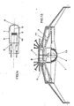
- FIG. 1a shows a halogen incandescent lamp according to the invention in longitudinal section
- FIG. 1b shows a longitudinal section through an operating light
- the halogen incandescent lamp with a base on one side has a cylinder-symmetrical lamp bulb 1, the side walls 2 of which are provided with an interference layer 3 in the cylinder jacket region.
- the interference layer has layers with alternating high and low refractive indices, the infrared components of the light generated in the lamp being reflected into the interior of the lamp bulb.
- the coating known from DE-OS 32 27 096 can be used as the interference layer; outside the actual cylinder jacket area, i.e. in the area of the dome 4 of the bulb or in the base area 5, the bulb is without an interference layer and thus transparent to infrared light.
- the infrared radiation generated in the lamp or reflected by the interference layer in the bulb emerges at a defined solid angle ⁇ along the cylinder axis 6 of the lamp bulb 1.
- the solid angle ⁇ is in the range from 20 to 160 °.
- the visible light radiating through the interference layer 3 reaches the reflector 7 partly directly, partly via deflection mirror 12, from which it is reflected into the actual illumination field; the infrared radiation, however, emerges through the uncoated base area 5 of the lamp bulb 1; it is led out of the optical system via the opening 8 in the reflector system 11 or the part of the reflector system 11 which transmits infrared light, and reaches heat-absorbing bodies directly or indirectly, which are not shown in FIG. 1b for a better overview; in the case of indirect radiation of the heat-absorbing bodies, the infrared light is guided to the heat-absorbing bodies via deflection mirrors. It is of course also possible to arrange the lamp bulb by rotating it through 180 ° such that the area of the dome 4 of the lamp bulb 1 is adjacent to the opening 8 located in the reflector system 11 or the part transmitting infrared light.
- the lamp according to the invention thus provides a spatial separation of the exit directions from visible light and infrared radiation.
- the optical system surrounding the lamp is designed in such a way that only the filament of the lamp is imaged in the light field, the light field is almost free of annoying heat radiation.
- the exemplary embodiment is explained using a halogen incandescent lamp; However, it is also possible to use a gas discharge lamp with a lamp bulb instead of the halogen incandescent lamp, the outer surface of which is provided with an interference filter which surrounds the discharge path of the lamp.
Landscapes
- Engineering & Computer Science (AREA)
- General Engineering & Computer Science (AREA)
- Physics & Mathematics (AREA)
- Spectroscopy & Molecular Physics (AREA)
- Non-Portable Lighting Devices Or Systems Thereof (AREA)
- Securing Globes, Refractors, Reflectors Or The Like (AREA)
Abstract
Eine Beleuchtungsanordnung aus einer Lichtquelle mit Lampenkolben und einem Reflektor weist ein auf einen Teil der Außenfläche des Lampenkolbens aufgebrachtes Interferenzfilter auf, das eine hohe Durchlässigkeit für sichtbares Licht und ein hohes Reflexionsvermögen für Infrarotlicht besitzt; der für Infrarotlicht durchlässige Lampenkolbenbereich ist solchen Bereichen des Reflektors benachbart, die Infrarotlicht absorbierend oder transmittierend ausgebildet sind.A lighting arrangement comprising a light source with a lamp bulb and a reflector has an interference filter applied to a part of the outer surface of the lamp bulb, which has a high permeability for visible light and a high reflectivity for infrared light; the lamp bulb region which is permeable to infrared light is adjacent to those regions of the reflector which are designed to absorb or transmit infrared light.
Description
Die Erfindung betrifft eine Beleuchtungsanordnung mit einer mit einem Lampenkolben versehenen Lichtquelle und mit einem der Lichtquelle zugeordneten Reflektor, wobei auf wenigstens einem Teil der Außenfläche des Lampenkolbens ein aus mehreren Schichten bestehendes Interferenzfilter aufgebracht ist, das eine hohe Durchlässigkeit für sichtbares Licht und ein hohes Reflexionsvermögen für Infrarotlicht aufweist.The invention relates to a lighting arrangement with a light bulb provided with a lamp bulb and with a reflector assigned to the light source, an interference filter consisting of several layers being applied to at least part of the outer surface of the lamp bulb, which has a high permeability for visible light and a high reflectivity for Has infrared light.
Es ist bekannt, Halogenglühlampen in verschiedenartigen optischen Systemen, wie beispielsweise Studio- und Operationsleuchten, oder Tageslichtprojektoren für Folien, einzusetzen, wobei stets ein möglichst geringer Infrarotlichtanteil in Strahlungsrichtung austreten soll, um die Wärmestrahlung im Beleuchtungsfeld zu reduzieren. Dies geschieht in der Regel durch Reflektoren, welche Infrarotlicht transmittieren und das sichtbare Licht reflektieren und/oder durch Filter an den Lichtaustrittsöffnungen, welche den Infrarotlichtanteil zum großen Teil absorbieren.It is known to use halogen incandescent lamps in various types of optical systems, such as studio and surgical lights, or daylight projectors for foils, with the smallest possible proportion of infrared light emerging in the direction of radiation in order to reduce the heat radiation in the lighting field. This is usually done by reflectors, which transmit infrared light and reflect the visible light and / or by filters at the light exit openings, which largely absorb the infrared light component.
Aus der DE-OS 32 27 096 ist eine zylindrische Halogenglühlampe mit einer entlang der Zylinderachse des Lampenkolbens geführten Glühwendel bekannt, deren Lampenkolben auf seiner Außenseite mit einem als Interferenzfilter wirkenden Mehrschichtkörper beschichtet ist, welcher die Infrarotanteile des in der Lampe erzeugten Lichtes auf die Wendel reflektiert, während er die sichtbaren Anteile des erzeugten Lichtes transmittiert. Das Interferenzfilter weist dabei Schichten mit alternierend hohem und niedrigem Brechungsindex auf, wobei die Materialen dieser Schichten im wesentlichen aus Siliziumdioxid und Tantalpentoxid bestehen. Durch eine ausreichend gute Justierung der Glühwendel entlang der Symmetrieachse des Lampenkolbens wird die reflektierte Infrarotstrahlung zum Teil von der Glühwendel absorbiert. Dadurch reduziert sich der Anteil der transmittierten Infrarotstrahlung, wobei der Wirkungsgrad der Lampe verbessert wird.From DE-OS 32 27 096 a cylindrical halogen incandescent lamp with a filament guided along the cylinder axis of the lamp bulb is known, the lamp bulb of which is coated on the outside with a multilayer body acting as an interference filter, which contains the infrared components of the light generated in the lamp reflects on the filament while it transmits the visible portions of the generated light. The interference filter has layers with alternating high and low refractive indices, the materials of these layers consisting essentially of silicon dioxide and tantalum pentoxide. By a sufficiently good adjustment of the filament along the axis of symmetry of the lamp bulb, the reflected infrared radiation is partially absorbed by the filament. This reduces the proportion of transmitted infrared radiation, and the efficiency of the lamp is improved.
Eine ähnliche Anordnung ist aus der US-PS 4,689,519 bekannt, nach der eine Glühlampe im zylinderförmigen Mittelteil ihres langgestreckten Lampenkolbens mit einem Interferenzfilter versehen ist, das die von der Wendel erzeugte Infrarot-Strahlung zur Reduzierung von Wärmeverlusten in den Lampenkolben reflektiert; das Filter besteht aus alternierend angeordneten Schichten mit einem niedrigen und einem hohen Brechnungsindex, wobei Siliziumdioxid und Tantalpentoxid eingesetzt werden; die beiden Kolbenenden sind ohne Tantalpentoxidbeschichtung, da eine Reflexion des Infrarotlichts auf die Wendel von hier aus uneffektiv ist.A similar arrangement is known from US Pat. No. 4,689,519, according to which an incandescent lamp is provided in the cylindrical central part of its elongated lamp bulb with an interference filter which reflects the infrared radiation generated by the filament to reduce heat losses in the lamp bulb; the filter consists of alternating layers with a low and a high refractive index, using silicon dioxide and tantalum pentoxide; the two ends of the piston are without tantalum pentoxide coating, since reflection of the infrared light on the filament is ineffective from here.
Weiterhin sind aus der DE-OS 15 89 095 Gasentladungslampen bekannt, deren Kolben mit einem optischen Interferenzfilter aus mehreren Teilschichten mit unterschiedlichen Brechungsindex versehen sind, um eine hitzebeständige Filteranordnung zur Erzeugung von farbneutralem Licht herzustellen.Furthermore, from DE-OS 15 89 095 gas discharge lamps are known, the bulbs of which are provided with an optical interference filter made of several partial layers with different refractive index, in order to produce a heat-resistant filter arrangement for generating color-neutral light.
Eine weitere Anwendung von Interferenzfiltern ist aus dem DE-GM 18 09 322 bekannt, in dem ein für Wärmestrahlen durchlässiger Kaltlichtspiegel beschrieben ist, dessen Oberfläche mit einer Reihe von interferierenden Dielektrikumschichten aus abwechselnd höher und niedrigbrechenden Substanzen bedeckt ist; als Schichtmaterialien werden dabei Siliziumoxid und Titanoxid oder Tantaloxid eingesetzt.Another application of interference filters is known from DE-GM 18 09 322, in which a cold light mirror that is permeable to heat rays is described, the surface of which is covered with a series of interfering dielectric layers made of alternately higher and lower refractive substances; Silicon oxide and titanium oxide or tantalum oxide are used as layer materials.
Bei Halogenglühlampen kleinerer Abmessungen ist es nicht möglich, durch Reflexion des Infrarotanteils an einem auf dem Kolben aufgebrachten Interferenzfilter das Infrarotlicht in der Wendel zu absorbieren, da die Symmetrieachse der Wendel in der Regel nicht mit der Symmetrieachse des Lampenkolbens zusammenfällt und in üblichen Ausführungsformen (z.B. einseitig gesockelte Lampe) senkrecht darauf steht.In the case of halogen incandescent lamps of smaller dimensions, it is not possible to absorb the infrared light in the filament by reflecting the infrared portion of an interference filter mounted on the bulb, since the axis of symmetry of the filament generally does not coincide with the axis of symmetry of the lamp bulb and in conventional embodiments (e.g. one-sided base lamp) is perpendicular to it.
Falls trotzdem eine Beschichtung des Lampenkolbens mit einem Interferenzfilter erfolgen würde, hätte dies eine Vielfachreflexion zur Folge, die jedoch infolge der Teildurchlässigkeit der Interferenzschicht schließlich zu einer Transmission des Infrarotanteils führen würde. Eine Reduzierung des Infrarotanteils wäre praktisch kaum zu erzielen.If the lamp bulb were nevertheless coated with an interference filter, this would result in multiple reflection, which, however, would ultimately lead to transmission of the infrared component due to the partial permeability of the interference layer. It would be practically impossible to reduce the infrared portion.
Die Erfindung stellt sich die Aufgabe, durch geometrische Zuordnung von Lichtquelle und Reflektor sowie durch teilweise Beschichtung der äußeren Kolbenfläche der Lichtquelle eine möglichst einfache Infrarotlicht-Abschirmung des Beleuchtungsfeldes zu erzielen, wobei Lampe und Reflektor trotz optimaler Wirksamkeit verhältnismäßig preisgünstig sind.The object of the invention is to achieve the simplest possible infrared light shielding of the illumination field by geometrically assigning the light source and reflector and by partially coating the outer bulb surface of the light source, the lamp and reflector being relatively inexpensive despite their optimal effectiveness.
Die Aufgabe wird durch die kennzeichnenden Merkmale des Anspruchs 1 gelöst. Weitere vorteilhafte Ausgestaltungen des Gegenstandes der Erfindung sind den Unteransprüchen zu entnehmen.The object is achieved by the characterizing features of claim 1. Further advantageous refinements of the subject matter of the invention can be found in the subclaims.
Bei einer bevorzugten Ausführungsform handelt es sich um eine einseitig gesockelte Halogenglühlampe, die so beschichtet ist, daß im Sockelbereich oder im Kuppelbereich des Lampenkolbens bzw. in beiden Bereichen Infrarotstrahlung austritt.A preferred embodiment is a halogen incandescent lamp with a base on one side, which is coated in such a way that infrared radiation emerges in the base region or in the dome region of the lamp bulb or in both regions.
Als vorteilhaft erweist sich der Wegfall von Filter und Filterhalterung, so daß sich ein verhältnismäßig einfacher, auch ohne Fachpersonal zu wartender Aufbau ergibt. Dies wikt sich insbesondere bei Operationsleuchten mit einer Vielzahl von einzelnen Lichtquellen als vorteilhaft aus. Darüber hinaus wird die Ersatzteilbevorratung vereinfacht, da keine separaten Infrarotstrahlung absorbierenden Filter mehr erforderlich sind.The elimination of the filter and filter holder has proven to be advantageous, so that the result is a relatively simple structure that can also be maintained without specialist personnel. This is particularly advantageous for surgical lights with a large number of individual light sources. In addition, the spare parts inventory is simplified because no separate infrared radiation absorbing filters are required.
Im folgenden ist der Gegenstand der Erfindung anhand eines Ausführungsbeispiels in der Zeichnung nachfolgend näher erläutert.The subject matter of the invention is explained in more detail below using an exemplary embodiment in the drawing.
Figur 1a zeigt im Längsschnitt eine erfindungsgemäße Halogenglühlampe, während in Figur 1b ein Längsschnitt durch eine Operationsleuchte dargestellt ist.FIG. 1a shows a halogen incandescent lamp according to the invention in longitudinal section, while FIG. 1b shows a longitudinal section through an operating light.
Gemäß Figur 1a weist die einseitig gesockelte Halogenglühlampe einen zylindersymmetrischen Lampenkolben 1 auf, dessen Seitenwände 2 im Zylindermantelbereich mit einer Interferenzschicht 3 versehen sind. Die Interferenzschicht weist Schichten mit alterniered hohem und niedrigem Brechungsindex auf, wobei die Infrarotanteile des in der Lampe erzeugten Lichtes in das Innere des Lampenkolbens reflektiert werden. Als Interferenzschicht kann dabei beispielsweise die aus der DE-OS 32 27 096 bekannte Beschichtung eingesetzt werden; außerhalb des eigentlichen Zylindermantelbereiches, d.h. im Bereich der Kuppel 4 des Kolbens bzw. im Sockelbereich 5 ist der Kolben ohne Interferenzschicht und somit für Infrarotlicht durchlässig. Die in der Lampe erzeugte bzw. über die Interferenzschicht in den Kolben reflektierte Infrarotstrahlung tritt in einem definierten Raumwinkel α entlang der Zylinderachse 6 des Lampenkolbens 1 aus. Der Raumwinkel α liegt im Bereich von 20 bis 160°.According to FIG. 1a, the halogen incandescent lamp with a base on one side has a cylinder-symmetrical lamp bulb 1, the
Gemäß Figur 1b gelangt das durch die Interferenzschicht 3 strahlende sichtbare Licht teilweise direkt, teilweise über Umlenkspiegel 12 auf den Reflektor 7, von dem es in das eigentliche Beleuchtungsfeld reflektiert wird; die Infrarotstrahlung tritt dagegen durch den unbeschichteten Sockelbereich 5 des Lampenkolbens 1 aus; sie wird über die im Reflektorsystem 11 befindliche Öffnung 8 bzw. den Infrarotlicht transmittierenden Teil des Reflektorsystems 11 aus dem optischen System hinausgeführt und gelangt direkt oder indirekt auf wärmeabsorbierende Körper, die zwecks besserer Übersicht in Figur 1b nicht dargestellt sind; bei indirekter Bestrahlung der wärmeabsorbierenden Körper wird das Infrarot licht über Umlenkspiegel zu den wärmeabsorbierenden Körpern geleitet. Es ist selbstverständlich auch möglich, dem Lampenkolben durch Drehung um 180° so anzuordnen, daß der Bereich der Kuppel 4 des Lampenkolbens 1 der im Reflektorsystem 11 befindlichen Öffnung 8 bzw. dem Infrarotlicht transmittierenden Teil benachbart ist.According to FIG. 1b, the visible light radiating through the
Weiterhin ist auch der Einsatz von Lampenkolben möglich, die sowohl im Bereich der Kuppel 4 als auch im Sockelbereich 5 für Infrarotlicht durchlässig sind; entsprechend Figur 1b wird in einem solchen Fall der aus der Kuppel 4 austretende Infrarotlichtanteil über Umlenkspiegel 12 entlang der Achse 6 des Lampenkolbens in die im Reflektorsystem 11 befindliche Öffnung 8 bzw. dem Infrarotlicht transmittierenden Teil des Reflektorsystems geleitet.It is also possible to use lamp bulbs which are transparent to infrared light both in the area of the
Während des Betriebes treten in radialer Richtung (zur Zylinderachse 6) Strahlenbündel sichtbaren Lichts mit maximaler Intensität aus, während in axialer Richtung Strahlenbündel von Infrarotlicht mit maximaler Intensität austreten. Es erfolgt somit durch die erfindungsgemäße Lampe eine räumliche Trennung der Austrittsrichtungen von sichtbarem Licht und Infrarotstrahlung.During operation, beams of visible light emerge at maximum intensity in the radial direction (to cylinder axis 6), while beams of infrared light emerge at maximum intensity in the axial direction. The lamp according to the invention thus provides a spatial separation of the exit directions from visible light and infrared radiation.
Ist das die Lampe umgebende optische System so ausgelegt, daß lediglich die Wendel der Lampe im Leuchtfeld abgebildet wird, so ist das Leuchtfeld nahezu frei von störender Wärmestrahlung.If the optical system surrounding the lamp is designed in such a way that only the filament of the lamp is imaged in the light field, the light field is almost free of annoying heat radiation.
Das Ausführungsbeispiel ist zwar anhand einer Halogenglühlampe erläutert; es ist jedoch auch möglich, anstelle der Halogenglühlampe eine Gasentladungslampe mit einem Lampenkolben einzusetzen, dessen äußere Fläche mit einem Interferenzfilter versehen ist, das die Entladungsstrecke der Lampe umschließt.The exemplary embodiment is explained using a halogen incandescent lamp; However, it is also possible to use a gas discharge lamp with a lamp bulb instead of the halogen incandescent lamp, the outer surface of which is provided with an interference filter which surrounds the discharge path of the lamp.
Claims (10)
Priority Applications (1)
| Application Number | Priority Date | Filing Date | Title |
|---|---|---|---|
| DE8817192U DE8817192U1 (en) | 1988-04-29 | 1988-11-11 | Lighting arrangement with halogen light bulb |
Applications Claiming Priority (2)
| Application Number | Priority Date | Filing Date | Title |
|---|---|---|---|
| DE3814539A DE3814539A1 (en) | 1988-04-29 | 1988-04-29 | LIGHTING ARRANGEMENT WITH HALOGEN BULB |
| DE3814539 | 1988-04-29 |
Publications (3)
| Publication Number | Publication Date |
|---|---|
| EP0339130A2 true EP0339130A2 (en) | 1989-11-02 |
| EP0339130A3 EP0339130A3 (en) | 1990-05-16 |
| EP0339130B1 EP0339130B1 (en) | 1995-04-12 |
Family
ID=6353206
Family Applications (1)
| Application Number | Title | Priority Date | Filing Date |
|---|---|---|---|
| EP88118811A Expired - Lifetime EP0339130B1 (en) | 1988-04-29 | 1988-11-11 | Lighting fixture with halogen lamp |
Country Status (4)
| Country | Link |
|---|---|
| US (1) | US4937714A (en) |
| EP (1) | EP0339130B1 (en) |
| JP (1) | JPH0244604A (en) |
| DE (2) | DE3814539A1 (en) |
Cited By (7)
| Publication number | Priority date | Publication date | Assignee | Title |
|---|---|---|---|---|
| EP0460913A3 (en) * | 1990-06-04 | 1992-08-26 | Toshiba Lighting & Technology Corporation | A lighting unit having a lamp and a reflector |
| EP0470496A3 (en) * | 1990-08-07 | 1992-08-26 | Toshiba Lighting & Technology Corporation | Incandescent lamp and reflector type projection lamp |
| FR2713825A1 (en) * | 1993-12-10 | 1995-06-16 | Gen Electric | Light source with an optical interference filter, method for forming such a filter and lighting system provided with such a light source. |
| EP0702396A3 (en) * | 1994-09-13 | 1997-01-29 | Osram Sylvania Inc | High efficiency vehicle headlights and reflector lamps |
| EP0883889A4 (en) * | 1996-02-27 | 1999-03-24 | Tailored Lighting Inc | Novel daylight lamp |
| WO1999046546A1 (en) * | 1998-03-11 | 1999-09-16 | Michael Bisges | Cold light-uv-radiation device |
| WO2009121554A1 (en) * | 2008-03-31 | 2009-10-08 | Osram Gesellschaft mit beschränkter Haftung | Illumination device |
Families Citing this family (14)
| Publication number | Priority date | Publication date | Assignee | Title |
|---|---|---|---|---|
| US5264961A (en) * | 1989-10-10 | 1993-11-23 | Unisys Corporation | Techniques for trapping beams of infra-red energy |
| US5146362A (en) * | 1989-10-10 | 1992-09-08 | Unisys Corporation | Infra-red extraction from illumination source |
| US5111367A (en) * | 1991-10-16 | 1992-05-05 | Churchill David L | Fiber optic lighting device |
| DE4140325C2 (en) * | 1991-12-06 | 2003-07-31 | Delma Elektro Med App | surgical light |
| DE19602329C2 (en) * | 1996-01-24 | 2001-08-16 | Heraeus Med Gmbh | Housing of an operating light |
| DE19621853A1 (en) * | 1996-05-31 | 1997-12-04 | Heraeus Med Gmbh | Method of irradiating an illumination field esp. using medical light with incandescent lamp e.g. for dentistry |
| JP3392701B2 (en) * | 1997-04-18 | 2003-03-31 | 株式会社小糸製作所 | Wedge-based bulb |
| US6402351B1 (en) | 1998-03-27 | 2002-06-11 | Hill-Rom Services, Inc., | Controls for a surgical light apparatus |
| DE10006409A1 (en) * | 2000-02-14 | 2001-08-16 | Zumtobel Staff Gmbh | Recessed ceiling light fitting has concave reflector and color filters positioned on either side of elongate lamp |
| US6880957B2 (en) * | 2002-03-28 | 2005-04-19 | Mark Wayne Walters | Lighting apparatus with electronic shadow compensation |
| TWI230269B (en) * | 2002-08-30 | 2005-04-01 | Seiko Epson Corp | Illuminating device, projector, and method of assembling illuminating device |
| KR100521179B1 (en) * | 2003-06-11 | 2005-10-12 | 현대자동차주식회사 | infrared rays irradiation apparatus for a night vision system |
| US8613528B2 (en) * | 2010-05-07 | 2013-12-24 | Abl Ip Holding Llc | Light fixtures comprising an enclosure and a heat sink |
| JP2012109155A (en) | 2010-11-18 | 2012-06-07 | Toshiba Lighting & Technology Corp | Lighting fixture |
Citations (4)
| Publication number | Priority date | Publication date | Assignee | Title |
|---|---|---|---|---|
| DE1589095A1 (en) | 1967-07-12 | 1970-03-05 | Braun Ag | Gas discharge lamp for flash units |
| DE3227096A1 (en) | 1981-07-20 | 1983-02-03 | Optical Coating Laboratory Inc., 95401 Santa Rosa, Calif. | OPTICAL COATINGS SUITABLE FOR HIGH TEMPERATURES |
| GB2183363A (en) | 1985-10-31 | 1987-06-03 | Toshiba Kk | Optical interference film |
| US4689519A (en) | 1985-10-23 | 1987-08-25 | U.S. Philips Corporation | Electric lamp having an outwardly extending protrusion |
Family Cites Families (16)
| Publication number | Priority date | Publication date | Assignee | Title |
|---|---|---|---|---|
| US1822076A (en) * | 1927-03-02 | 1931-09-08 | Zeiss Carl Fa | Illuminating arrangement |
| US2069950A (en) * | 1933-11-02 | 1937-02-09 | Ernest H Greppin | Surgical lamp |
| US2852980A (en) * | 1948-12-27 | 1958-09-23 | Schroder Hubert | Infra-red transmitting mirror |
| US3174067A (en) * | 1960-07-21 | 1965-03-16 | Patent Treuhand Ges Fuer Elektrische Gluehlampen Mbh | Construction for projection lamps eliminating undesired infrared radiation |
| DE1201278B (en) * | 1962-05-04 | 1965-09-23 | Quarzlampen Gmbh | Operating light |
| DE1497325A1 (en) * | 1966-07-30 | 1969-10-30 | Original Hanau Quarzlampen | Operating light with diffuser |
| US3511983A (en) * | 1967-04-10 | 1970-05-12 | Corning Glass Works | Lighting device for dental and surgical procedures |
| US4161014A (en) * | 1976-08-23 | 1979-07-10 | Bausch & Lomb Incorporated | Luminaire having a configured interference mirror and reflector |
| US4254455A (en) * | 1979-12-21 | 1981-03-03 | Pelton & Crane Company | Reflector for dental, medical or the like lighting device |
| JPS5725738A (en) * | 1980-07-23 | 1982-02-10 | Toshiba Electric Equip Corp | Illuminating device |
| US4380794A (en) * | 1981-06-15 | 1983-04-19 | Sybron Corporation | Surgical lamp characterized by having an improved reflector |
| US4663557A (en) * | 1981-07-20 | 1987-05-05 | Optical Coating Laboratory, Inc. | Optical coatings for high temperature applications |
| JPH06100687B2 (en) * | 1983-08-22 | 1994-12-12 | 東芝ライテック株式会社 | Bulb |
| DE3339789C2 (en) * | 1983-11-03 | 1985-09-19 | Jürgen 8022 Grünwald Brandt | Medical lamp |
| HU190574B (en) * | 1984-06-25 | 1986-09-29 | Tunsgram Reszvenytarsasag,Hu | Light source with flattened glass envelope, preferably halogen incandescent lamp and method for fastening the body of the lamp to the housing or optical element |
| JPS6217904A (en) * | 1985-07-15 | 1987-01-26 | 双葉電子工業株式会社 | Light source |
-
1988
- 1988-04-29 DE DE3814539A patent/DE3814539A1/en active Granted
- 1988-11-11 DE DE3853583T patent/DE3853583D1/en not_active Expired - Fee Related
- 1988-11-11 EP EP88118811A patent/EP0339130B1/en not_active Expired - Lifetime
-
1989
- 1989-01-26 US US07/302,575 patent/US4937714A/en not_active Expired - Lifetime
- 1989-04-20 JP JP1099036A patent/JPH0244604A/en active Granted
Patent Citations (4)
| Publication number | Priority date | Publication date | Assignee | Title |
|---|---|---|---|---|
| DE1589095A1 (en) | 1967-07-12 | 1970-03-05 | Braun Ag | Gas discharge lamp for flash units |
| DE3227096A1 (en) | 1981-07-20 | 1983-02-03 | Optical Coating Laboratory Inc., 95401 Santa Rosa, Calif. | OPTICAL COATINGS SUITABLE FOR HIGH TEMPERATURES |
| US4689519A (en) | 1985-10-23 | 1987-08-25 | U.S. Philips Corporation | Electric lamp having an outwardly extending protrusion |
| GB2183363A (en) | 1985-10-31 | 1987-06-03 | Toshiba Kk | Optical interference film |
Cited By (8)
| Publication number | Priority date | Publication date | Assignee | Title |
|---|---|---|---|---|
| EP0460913A3 (en) * | 1990-06-04 | 1992-08-26 | Toshiba Lighting & Technology Corporation | A lighting unit having a lamp and a reflector |
| EP0470496A3 (en) * | 1990-08-07 | 1992-08-26 | Toshiba Lighting & Technology Corporation | Incandescent lamp and reflector type projection lamp |
| FR2713825A1 (en) * | 1993-12-10 | 1995-06-16 | Gen Electric | Light source with an optical interference filter, method for forming such a filter and lighting system provided with such a light source. |
| EP0702396A3 (en) * | 1994-09-13 | 1997-01-29 | Osram Sylvania Inc | High efficiency vehicle headlights and reflector lamps |
| EP0883889A4 (en) * | 1996-02-27 | 1999-03-24 | Tailored Lighting Inc | Novel daylight lamp |
| WO1999046546A1 (en) * | 1998-03-11 | 1999-09-16 | Michael Bisges | Cold light-uv-radiation device |
| US6621087B1 (en) | 1998-03-11 | 2003-09-16 | Arccure Technologies Gmbh | Cold light UV irradiation device |
| WO2009121554A1 (en) * | 2008-03-31 | 2009-10-08 | Osram Gesellschaft mit beschränkter Haftung | Illumination device |
Also Published As
| Publication number | Publication date |
|---|---|
| DE3814539C2 (en) | 1990-05-23 |
| JPH0468721B2 (en) | 1992-11-04 |
| EP0339130A3 (en) | 1990-05-16 |
| DE3853583D1 (en) | 1995-05-18 |
| DE3814539A1 (en) | 1989-11-09 |
| US4937714A (en) | 1990-06-26 |
| EP0339130B1 (en) | 1995-04-12 |
| JPH0244604A (en) | 1990-02-14 |
Similar Documents
| Publication | Publication Date | Title |
|---|---|---|
| EP0339130A2 (en) | Lighting fixture with halogen lamp | |
| DE60222793T2 (en) | LIGHTING UNIT | |
| DE3620789C2 (en) | Dimmed automotive headlights | |
| DE3750683T2 (en) | Reflector-type lamp with reduced focal loss. | |
| DE69130738T2 (en) | REFLECTOR WITH LAMP | |
| DE3740901A1 (en) | LAMP | |
| EP0663684B1 (en) | Reflector lamp | |
| DE2644977C2 (en) | Reflector lamp with an electric light source | |
| EP0986093B1 (en) | Incandescent lamp | |
| DE69205407T2 (en) | Reflector lamp with improved cover panel. | |
| DE69609546T2 (en) | Light bulb | |
| DE69705251T2 (en) | Coupling arrangement with several connections with a small numerical aperture | |
| EP0401711B1 (en) | Lamp configuration, especially for signal device | |
| DE69502237T2 (en) | Light source | |
| DE3213444A1 (en) | ELECTRIC REFLECTOR LAMP | |
| EP1045195B1 (en) | Luminaire | |
| DE3878367T2 (en) | HEADLIGHT SYSTEM AND ELECTRIC LAMP DAFUER. | |
| DE29706435U1 (en) | Light source for use in leak detection in heating, ventilation and air conditioning systems that use environmentally friendly materials | |
| DE69516826T2 (en) | Incandescent lamp and lighting device using this lamp | |
| DE10211015A1 (en) | reflector lamp | |
| CH652531A5 (en) | BULB. | |
| DE8817192U1 (en) | Lighting arrangement with halogen light bulb | |
| DE102004054872B4 (en) | reflector lamp | |
| DE19621853A1 (en) | Method of irradiating an illumination field esp. using medical light with incandescent lamp e.g. for dentistry | |
| EP0774618A1 (en) | Reflector for a radiant light source and use of it |
Legal Events
| Date | Code | Title | Description |
|---|---|---|---|
| PUAI | Public reference made under article 153(3) epc to a published international application that has entered the european phase |
Free format text: ORIGINAL CODE: 0009012 |
|
| 17P | Request for examination filed |
Effective date: 19881118 |
|
| AK | Designated contracting states |
Kind code of ref document: A2 Designated state(s): DE FR GB |
|
| PUAL | Search report despatched |
Free format text: ORIGINAL CODE: 0009013 |
|
| AK | Designated contracting states |
Kind code of ref document: A3 Designated state(s): DE FR GB |
|
| RAP1 | Party data changed (applicant data changed or rights of an application transferred) |
Owner name: HERAEUS INSTRUMENTS GMBH |
|
| 17Q | First examination report despatched |
Effective date: 19930305 |
|
| RAP1 | Party data changed (applicant data changed or rights of an application transferred) |
Owner name: HERAEUS MED GMBH |
|
| GRAA | (expected) grant |
Free format text: ORIGINAL CODE: 0009210 |
|
| AK | Designated contracting states |
Kind code of ref document: B1 Designated state(s): DE FR GB |
|
| GBT | Gb: translation of ep patent filed (gb section 77(6)(a)/1977) |
Effective date: 19950411 |
|
| REF | Corresponds to: |
Ref document number: 3853583 Country of ref document: DE Date of ref document: 19950518 |
|
| ET | Fr: translation filed | ||
| PLBQ | Unpublished change to opponent data |
Free format text: ORIGINAL CODE: EPIDOS OPPO |
|
| PLBI | Opposition filed |
Free format text: ORIGINAL CODE: 0009260 |
|
| 26 | Opposition filed |
Opponent name: BERCHTOLD GMBH & CO. Effective date: 19951130 |
|
| PLBF | Reply of patent proprietor to notice(s) of opposition |
Free format text: ORIGINAL CODE: EPIDOS OBSO |
|
| PLBF | Reply of patent proprietor to notice(s) of opposition |
Free format text: ORIGINAL CODE: EPIDOS OBSO |
|
| PLBO | Opposition rejected |
Free format text: ORIGINAL CODE: EPIDOS REJO |
|
| APAC | Appeal dossier modified |
Free format text: ORIGINAL CODE: EPIDOS NOAPO |
|
| APAE | Appeal reference modified |
Free format text: ORIGINAL CODE: EPIDOS REFNO |
|
| APAC | Appeal dossier modified |
Free format text: ORIGINAL CODE: EPIDOS NOAPO |
|
| PLBN | Opposition rejected |
Free format text: ORIGINAL CODE: 0009273 |
|
| STAA | Information on the status of an ep patent application or granted ep patent |
Free format text: STATUS: OPPOSITION REJECTED |
|
| 27O | Opposition rejected |
Effective date: 19980424 |
|
| REG | Reference to a national code |
Ref country code: GB Ref legal event code: IF02 |
|
| PGFP | Annual fee paid to national office [announced via postgrant information from national office to epo] |
Ref country code: FR Payment date: 20031124 Year of fee payment: 16 Ref country code: DE Payment date: 20031124 Year of fee payment: 16 |
|
| PGFP | Annual fee paid to national office [announced via postgrant information from national office to epo] |
Ref country code: GB Payment date: 20031126 Year of fee payment: 16 |
|
| PG25 | Lapsed in a contracting state [announced via postgrant information from national office to epo] |
Ref country code: GB Free format text: LAPSE BECAUSE OF NON-PAYMENT OF DUE FEES Effective date: 20041111 |
|
| PG25 | Lapsed in a contracting state [announced via postgrant information from national office to epo] |
Ref country code: DE Free format text: LAPSE BECAUSE OF NON-PAYMENT OF DUE FEES Effective date: 20050601 |
|
| GBPC | Gb: european patent ceased through non-payment of renewal fee |
Effective date: 20041111 |
|
| PG25 | Lapsed in a contracting state [announced via postgrant information from national office to epo] |
Ref country code: FR Free format text: LAPSE BECAUSE OF NON-PAYMENT OF DUE FEES Effective date: 20050729 |
|
| REG | Reference to a national code |
Ref country code: FR Ref legal event code: ST |
|
| APAH | Appeal reference modified |
Free format text: ORIGINAL CODE: EPIDOSCREFNO |