EP0338741A2 - Kommutator für einen elektrischen Motor - Google Patents
Kommutator für einen elektrischen Motor Download PDFInfo
- Publication number
- EP0338741A2 EP0338741A2 EP89303750A EP89303750A EP0338741A2 EP 0338741 A2 EP0338741 A2 EP 0338741A2 EP 89303750 A EP89303750 A EP 89303750A EP 89303750 A EP89303750 A EP 89303750A EP 0338741 A2 EP0338741 A2 EP 0338741A2
- Authority
- EP
- European Patent Office
- Prior art keywords
- base
- commutator
- arm
- collar
- wall
- Prior art date
- Legal status (The legal status is an assumption and is not a legal conclusion. Google has not performed a legal analysis and makes no representation as to the accuracy of the status listed.)
- Withdrawn
Links
- 238000005242 forging Methods 0.000 claims description 3
- 239000012777 electrically insulating material Substances 0.000 claims description 2
- 239000002861 polymer material Substances 0.000 claims description 2
- 230000000284 resting effect Effects 0.000 claims 1
- 239000000463 material Substances 0.000 description 3
- 238000000034 method Methods 0.000 description 2
- 238000012986 modification Methods 0.000 description 2
- 230000004048 modification Effects 0.000 description 2
- 229920003023 plastic Polymers 0.000 description 2
- 239000004033 plastic Substances 0.000 description 2
- 238000004804 winding Methods 0.000 description 2
- RYGMFSIKBFXOCR-UHFFFAOYSA-N Copper Chemical compound [Cu] RYGMFSIKBFXOCR-UHFFFAOYSA-N 0.000 description 1
- 230000001133 acceleration Effects 0.000 description 1
- 230000001154 acute effect Effects 0.000 description 1
- 229910052802 copper Inorganic materials 0.000 description 1
- 239000010949 copper Substances 0.000 description 1
- 238000009413 insulation Methods 0.000 description 1
- 238000003754 machining Methods 0.000 description 1
- 210000002105 tongue Anatomy 0.000 description 1
- 238000003466 welding Methods 0.000 description 1
Images
Classifications
-
- H—ELECTRICITY
- H01—ELECTRIC ELEMENTS
- H01R—ELECTRICALLY-CONDUCTIVE CONNECTIONS; STRUCTURAL ASSOCIATIONS OF A PLURALITY OF MUTUALLY-INSULATED ELECTRICAL CONNECTING ELEMENTS; COUPLING DEVICES; CURRENT COLLECTORS
- H01R43/00—Apparatus or processes specially adapted for manufacturing, assembling, maintaining, or repairing of line connectors or current collectors or for joining electric conductors
- H01R43/06—Manufacture of commutators
-
- H—ELECTRICITY
- H01—ELECTRIC ELEMENTS
- H01R—ELECTRICALLY-CONDUCTIVE CONNECTIONS; STRUCTURAL ASSOCIATIONS OF A PLURALITY OF MUTUALLY-INSULATED ELECTRICAL CONNECTING ELEMENTS; COUPLING DEVICES; CURRENT COLLECTORS
- H01R39/00—Rotary current collectors, distributors or interrupters
- H01R39/02—Details for dynamo electric machines
- H01R39/04—Commutators
Definitions
- the present invention relates to a commutator for an electric motor, and in particular to an assembled commutator for a fractional horsepower permanent magnet direct current motor.
- One type of assembled commutator comprises a plastics base supporting a plurality of segments.
- the segments are form locked to the base, for example by providing tongues on the segments which are received in recesses in the base.
- Each segment has a tang which extends radially outwards and has a U-shaped portion which may be supported by a collar at one end of the base.
- To connect an armature coil to the segment the coil wire is wrapped into the base of the U-shape which is then collapsed onto the wire and heated in a hot forging or resistance welding process to burn off the insulation covering on the wire and form an electrical and mechanical connection with the wire.
- the segments are usually slid axially onto the base, in the direction of the collar.
- the electric motors are subject to high G-forces, particularly in motor vehicles where there is often rapid acceleration and deceleration. This may result in axial movement of the segments on the commutator base, which may place a strain on the connection between the segment and the armature winding as well as upsetting the geometry of the commutator.
- the present invention provides an assembled commutator comprising a cylindrical base of electrically insulating material, a plurality of commutator segments mounted on the base, each segment comprising a brush contacting portion which is supported by the base and a generally radially extending tang at one axial end of said brush contacting portion for connection to an armature coil wire, said tang being formlocked to said base, characterised in that said formlocking connection includes an edge on a radially extending arm, said arm being folded about a line generally parallel to the axial direction of the base and behind a radially extending wall on the base so that said edge bears against said wall to prevent movement of the segment in the direction from said one end to the other end.
- the natural resilience of the segment material which tends to cause a folded part to spring back slightly, will not affect the fit of the edge of the arm against the wall.
- the arm By tapering the arm slightly, the arm can be made to pull the segment tightly onto the base as it is folded behind the wall.
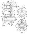
- the drawings show an embodiment of an assembled commutator 1 constructed in accordance with the invention.
- the commutator 1 comprises an electrically insulating base 2 which is integrally moulded from plastics material, preferably a crystalline polymer material.
- plastics material preferably a crystalline polymer material.
- One such material is marketed under the trade name XYDAR sold by DARTCO Manufacturing Co. of the U.S.A.
- the base 2 comprises a cylindrical portion 3 having a collar 4 formed at one end, and a stub-like extension 5 extending beyond the collar 4.
- the base 2 has a cylindrical inner bore 6 for mounting on a motor shaft (not shown).
- An end wall 7 of the cylindrical portion 3 opposite the collar 4 has recesses 8 which connect the outer surface 9 of the portion 3 with apertures 10 extending into the base from the end wall 7.
- the collar 4 is generally cylindrical and has a circumferential outer surface 11, a radially extending front wall 12 and a radially extending rear wall 13. Five, evenly spaced buttresses 14 are formed on the rear wall 13. Five evenly spaced cuboid protrusions 15 are formed on the front wall 12. The protrusions 15 are spaced from the outer surface 9 of the cylindrical portion 1 and level with the outer circumferential surface 11 of the collar 4.
- the base 2 carries five commutator segments 16.
- the segments are stamped from copper sheet and folded to shape.
- Each segment comprises an arcuate brush contacting portion 17 which sits on the surface 9.
- a reentrant tab 27 is formed at a front end of the portion 17.
- Tab 27 sits in a respective recess 8 and projects into an aperture 10.
- Ends 18 of the tabs 27 have a detent 19 to wedge the ends in the respective apertures 10 ( Figure 4).
- a tang 20 is formed at the rear end of each brush contacting portion 17.
- a tang 20 comprises a radially extending wall 21 which is slightly narrower than the width of the portion 17.
- the wall 21 has an aperture 22 which snugly receives a projection 15, the portion 17 fitting between the projection 15 and the surface 9 (see Figure 4).
- a U-shaped wire receiving portion 23 is formed at the outer end of the wall 21. This has a first arm 24 which rests on the circimferential surface 12 of the collar 4 and a second arm 25 extending at an acute angle to the first arm 24.
- the first arm 24 is wider than the second arm 24 in the circumferential direction such that it has two "wings" 26 which extend to either side of the second arm 25 when it is pressed down onto the first arm.
- arms 28 Extending laterally from the wings 26 are arms 28.
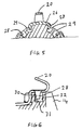
- the arms 28 are folded into recesses 29 provided in the circumferential surface 11 of the collar 4.
- the arms 28 and recesses 29 are arranged so that an edge 30 of each arm abuts a wall 31, thus preventing movement of the segment in the axial direction, towards the end wall 7.
- edge 30 of the arm 28 be tapered (see Figure 6) so as to progressively pull the segment tang wall portion 21 tightly against the wall 12 as the arm 28 is folded into the recess 29.
- the arm 28 may be arranged to be a tight fit in the recess, so as to abut the wall 31 and opposite wall 32 to prevent axial movement in either direction.
- the segments 16 are spaced apart on the surface of the cylindrical portion 3.
- the segments 16 are slid onto the base 2 along the surface 9. Ends 18 of the tabs 27 are pushed into the apertures 10, the tang wall portions 21 sliding over the protrusions 15.
- the base 1 has chamfered edges to facilitate the mounting of the segments 16.
- the arms 28 are then pressed into the recesses 29 to lock the segments on the base.
- the assembled commutator is mounted on a motor shaft, the extension 5 abutting the armature core. Coils are wound on the armature and the wire looped around respective tangs 20 at the end of each coil winding.
- the tangs 20 are hot forged or resistance welded to the wire in the usual manner, but with electrodes bearing on the arm 25, and, preferably, a forked electrode bearing on the wings 26 of the arm 24. Hence, heat evolved during the forging process is largely limited to the region of the collar 4.
Landscapes
- Engineering & Computer Science (AREA)
- Manufacturing & Machinery (AREA)
- Motor Or Generator Current Collectors (AREA)
Applications Claiming Priority (2)
| Application Number | Priority Date | Filing Date | Title |
|---|---|---|---|
| GB8809271 | 1988-04-20 | ||
| GB8809271A GB2217922A (en) | 1988-04-20 | 1988-04-20 | Commutator for an electric motor |
Publications (2)
| Publication Number | Publication Date |
|---|---|
| EP0338741A2 true EP0338741A2 (de) | 1989-10-25 |
| EP0338741A3 EP0338741A3 (de) | 1991-06-05 |
Family
ID=10635480
Family Applications (1)
| Application Number | Title | Priority Date | Filing Date |
|---|---|---|---|
| EP19890303750 Withdrawn EP0338741A3 (de) | 1988-04-20 | 1989-04-14 | Kommutator für einen elektrischen Motor |
Country Status (6)
| Country | Link |
|---|---|
| US (1) | US4956572A (de) |
| EP (1) | EP0338741A3 (de) |
| JP (1) | JPH0217848A (de) |
| CN (1) | CN1037621A (de) |
| BR (1) | BR8901847A (de) |
| GB (1) | GB2217922A (de) |
Families Citing this family (7)
| Publication number | Priority date | Publication date | Assignee | Title |
|---|---|---|---|---|
| ES2065983T3 (es) * | 1988-01-19 | 1995-03-01 | Johnson Electric Sa | Conmutador montado para un motor electrico. |
| US5189329A (en) * | 1988-09-26 | 1993-02-23 | Johnson Electric S.A. | Assembled commutator |
| US5134329A (en) * | 1989-01-26 | 1992-07-28 | Siemens Aktiengesellschaft | Self-ventilated electrical machine with arrangement to facilitate assembly and dismantling of the ventilator disk |
| US5272404A (en) * | 1991-03-01 | 1993-12-21 | Mabuchi Motor, Co., Ltd. | Miniature motor having a built-up commutator |
| JPH06169555A (ja) * | 1992-11-30 | 1994-06-14 | Mabuchi Motor Co Ltd | 小型モータ |
| JP2015192536A (ja) * | 2014-03-28 | 2015-11-02 | 紘一 浜田 | モータ及びモータ用電機子 |
| CN104158055B (zh) * | 2014-07-31 | 2016-04-06 | 瑞安市恒丰机电有限公司 | 换向器的加工方法 |
Family Cites Families (14)
| Publication number | Priority date | Publication date | Assignee | Title |
|---|---|---|---|---|
| US1410914A (en) * | 1917-10-23 | 1922-03-28 | Forest H Hartzell | Commutator for electric motors |
| GB281860A (en) * | 1926-11-19 | 1927-12-15 | British Thomson Houston Co Ltd | Improvements in and relating to commutators for dynamo electric machines and methodsof manufacturing the same |
| US1898929A (en) * | 1929-05-16 | 1933-02-21 | Herbert F Apple | Commutator and method of making it |
| GB630807A (en) * | 1947-06-27 | 1949-10-21 | Smith & Sons Ltd S | Improvements in or relating to electric commutators |
| DE1072310B (de) * | 1956-09-08 | |||
| GB1223677A (en) * | 1967-06-29 | 1971-03-03 | Gen Motors Ltd | A dynamo electric machine rotor shaft and commutator shell assembly |
| DE2601845A1 (de) * | 1976-01-20 | 1977-07-21 | Kautt & Bux Kg | Kollektor und verfahren zu seiner herstellung |
| FR2524212A1 (fr) * | 1982-03-23 | 1983-09-30 | Mecanismes Comp Ind De | Collecteur pour moteur electrique miniature |
| GB2128818B (en) * | 1982-10-11 | 1986-02-12 | Johnson Electric Ind Mfg | An armature |
| DE3530652A1 (de) * | 1985-08-28 | 1987-03-12 | Bosch Gmbh Robert | Kommutator fuer elektrische maschinen |
| GB2203292B (en) * | 1987-03-27 | 1992-01-08 | Johnson Electric Ind Mfg | Commutator |
| GB8714683D0 (en) * | 1987-06-23 | 1987-07-29 | Johnson Electric Ind Mfg | Commutator for electric motor |
| GB2207292A (en) * | 1987-07-09 | 1989-01-25 | Johnson Electric Ind Mfg | Electric motor |
| JP2811293B2 (ja) * | 1995-06-23 | 1998-10-15 | 株式会社アトム農機 | バケット |
-
1988
- 1988-04-20 GB GB8809271A patent/GB2217922A/en not_active Withdrawn
-
1989
- 1989-04-14 EP EP19890303750 patent/EP0338741A3/de not_active Withdrawn
- 1989-04-19 BR BR898901847A patent/BR8901847A/pt unknown
- 1989-04-19 JP JP1099894A patent/JPH0217848A/ja active Pending
- 1989-04-20 US US07/340,827 patent/US4956572A/en not_active Expired - Fee Related
- 1989-04-20 CN CN89102612A patent/CN1037621A/zh active Pending
Also Published As
| Publication number | Publication date |
|---|---|
| EP0338741A3 (de) | 1991-06-05 |
| GB2217922A (en) | 1989-11-01 |
| JPH0217848A (ja) | 1990-01-22 |
| CN1037621A (zh) | 1989-11-29 |
| GB8809271D0 (en) | 1988-05-25 |
| BR8901847A (pt) | 1989-11-28 |
| US4956572A (en) | 1990-09-11 |
Similar Documents
| Publication | Publication Date | Title |
|---|---|---|
| US5717270A (en) | Noise suppression capacitor arrangement on a rotor of an electric motor | |
| US4342934A (en) | Prefabricated brush holder assembly for use in small electric motors | |
| JP3364847B2 (ja) | 接続要素 | |
| EP0695019B1 (de) | Elektromachinerotor, insbesondere für einen Elektromotor, der eine Wärmkraftmaschine eines Fahrzeugs anfählt und Vorrichtung für seine Herstellung | |
| US5689148A (en) | Multi-pole, two-speed brush holder assembly | |
| US4642885A (en) | Method of assembling a stator | |
| EP0325367B1 (de) | Zusammengesetzter Stromwender für einen Elektromotor | |
| US5773907A (en) | Brush holder assemblies having novel brush holders | |
| EP0544404B1 (de) | Kleinmotor mit einer installierten Erdklemme | |
| US4544856A (en) | Dynamoelectric machine and stator | |
| EP0364292B1 (de) | Zusammengesetzter Kommutator | |
| GB2222730A (en) | Thermistor connected between electric motor brush arm and brush terminal | |
| US4956572A (en) | Commutator for an electric motor | |
| CA1290383C (en) | Connection of motor brush holder to stator coil | |
| US8362664B2 (en) | Rotating electrical machine | |
| CA1288124C (en) | Brush-holder plate in particular for an electric motor | |
| KR20070045298A (ko) | 콘택 브러시 홀더 | |
| EP0932242A1 (de) | Bürstenträger befestigt auf der Abdeckung des Gehäuses | |
| EP0280386A1 (de) | Verbindungen zum Kommutator in einem elektrischen Motor | |
| GB2253745A (en) | Securing commutator segments to commutator base for a miniature motor | |
| GB2215141A (en) | Connection of windings to commutator preventing heat distortion | |
| US4855632A (en) | Assembled commutators | |
| EP0650243A1 (de) | Bürstenanordnung | |
| GB2203292A (en) | Suppressor connection for commutator segment | |
| EP0759652A1 (de) | Kollektor |
Legal Events
| Date | Code | Title | Description |
|---|---|---|---|
| PUAI | Public reference made under article 153(3) epc to a published international application that has entered the european phase |
Free format text: ORIGINAL CODE: 0009012 |
|
| AK | Designated contracting states |
Kind code of ref document: A2 Designated state(s): DE ES FR GB IT |
|
| 17P | Request for examination filed |
Effective date: 19900501 |
|
| PUAL | Search report despatched |
Free format text: ORIGINAL CODE: 0009013 |
|
| AK | Designated contracting states |
Kind code of ref document: A3 Designated state(s): DE ES FR GB IT |
|
| STAA | Information on the status of an ep patent application or granted ep patent |
Free format text: STATUS: THE APPLICATION HAS BEEN WITHDRAWN |
|
| 18W | Application withdrawn |
Withdrawal date: 19911210 |
|
| R18W | Application withdrawn (corrected) |
Effective date: 19911210 |