EP0338708B1 - Kraftstoffpumpenvorrichtung - Google Patents
Kraftstoffpumpenvorrichtung Download PDFInfo
- Publication number
- EP0338708B1 EP0338708B1 EP19890303495 EP89303495A EP0338708B1 EP 0338708 B1 EP0338708 B1 EP 0338708B1 EP 19890303495 EP19890303495 EP 19890303495 EP 89303495 A EP89303495 A EP 89303495A EP 0338708 B1 EP0338708 B1 EP 0338708B1
- Authority
- EP
- European Patent Office
- Prior art keywords
- lever
- sleeve
- fuel
- distributor member
- stop
- Prior art date
- Legal status (The legal status is an assumption and is not a legal conclusion. Google has not performed a legal analysis and makes no representation as to the accuracy of the status listed.)
- Expired
Links
- 239000000446 fuel Substances 0.000 title claims description 24
- 238000005086 pumping Methods 0.000 title claims description 5
- 239000012530 fluid Substances 0.000 claims description 9
- 239000007788 liquid Substances 0.000 claims description 4
- 238000002347 injection Methods 0.000 claims description 3
- 239000007924 injection Substances 0.000 claims description 3
- 238000005553 drilling Methods 0.000 description 4
- 230000000694 effects Effects 0.000 description 3
- 230000002093 peripheral effect Effects 0.000 description 3
- 230000006835 compression Effects 0.000 description 2
- 238000007906 compression Methods 0.000 description 2
- 230000000295 complement effect Effects 0.000 description 1
- 238000003466 welding Methods 0.000 description 1
Images

Classifications
-
- F—MECHANICAL ENGINEERING; LIGHTING; HEATING; WEAPONS; BLASTING
- F02—COMBUSTION ENGINES; HOT-GAS OR COMBUSTION-PRODUCT ENGINE PLANTS
- F02M—SUPPLYING COMBUSTION ENGINES IN GENERAL WITH COMBUSTIBLE MIXTURES OR CONSTITUENTS THEREOF
- F02M41/00—Fuel-injection apparatus with two or more injectors fed from a common pressure-source sequentially by means of a distributor
- F02M41/08—Fuel-injection apparatus with two or more injectors fed from a common pressure-source sequentially by means of a distributor the distributor and pumping elements being combined
- F02M41/14—Fuel-injection apparatus with two or more injectors fed from a common pressure-source sequentially by means of a distributor the distributor and pumping elements being combined rotary distributor supporting pump pistons
- F02M41/1405—Fuel-injection apparatus with two or more injectors fed from a common pressure-source sequentially by means of a distributor the distributor and pumping elements being combined rotary distributor supporting pump pistons pistons being disposed radially with respect to rotation axis
- F02M41/1411—Fuel-injection apparatus with two or more injectors fed from a common pressure-source sequentially by means of a distributor the distributor and pumping elements being combined rotary distributor supporting pump pistons pistons being disposed radially with respect to rotation axis characterised by means for varying fuel delivery or injection timing
-
- F—MECHANICAL ENGINEERING; LIGHTING; HEATING; WEAPONS; BLASTING
- F02—COMBUSTION ENGINES; HOT-GAS OR COMBUSTION-PRODUCT ENGINE PLANTS
- F02D—CONTROLLING COMBUSTION ENGINES
- F02D1/00—Controlling fuel-injection pumps, e.g. of high pressure injection type
- F02D1/02—Controlling fuel-injection pumps, e.g. of high pressure injection type not restricted to adjustment of injection timing, e.g. varying amount of fuel delivered
- F02D1/06—Controlling fuel-injection pumps, e.g. of high pressure injection type not restricted to adjustment of injection timing, e.g. varying amount of fuel delivered by means dependent on pressure of engine working fluid
- F02D1/065—Controlling fuel-injection pumps, e.g. of high pressure injection type not restricted to adjustment of injection timing, e.g. varying amount of fuel delivered by means dependent on pressure of engine working fluid of intake of air
-
- F—MECHANICAL ENGINEERING; LIGHTING; HEATING; WEAPONS; BLASTING
- F02—COMBUSTION ENGINES; HOT-GAS OR COMBUSTION-PRODUCT ENGINE PLANTS
- F02D—CONTROLLING COMBUSTION ENGINES
- F02D1/00—Controlling fuel-injection pumps, e.g. of high pressure injection type
- F02D1/02—Controlling fuel-injection pumps, e.g. of high pressure injection type not restricted to adjustment of injection timing, e.g. varying amount of fuel delivered
- F02D1/08—Transmission of control impulse to pump control, e.g. with power drive or power assistance
- F02D1/12—Transmission of control impulse to pump control, e.g. with power drive or power assistance non-mechanical, e.g. hydraulic
-
- F—MECHANICAL ENGINEERING; LIGHTING; HEATING; WEAPONS; BLASTING
- F02—COMBUSTION ENGINES; HOT-GAS OR COMBUSTION-PRODUCT ENGINE PLANTS
- F02M—SUPPLYING COMBUSTION ENGINES IN GENERAL WITH COMBUSTIBLE MIXTURES OR CONSTITUENTS THEREOF
- F02M59/00—Pumps specially adapted for fuel-injection and not provided for in groups F02M39/00 -F02M57/00, e.g. rotary cylinder-block type of pumps
- F02M59/44—Details, components parts, or accessories not provided for in, or of interest apart from, the apparatus of groups F02M59/02 - F02M59/42; Pumps having transducers, e.g. to measure displacement of pump rack or piston
- F02M59/447—Details, components parts, or accessories not provided for in, or of interest apart from, the apparatus of groups F02M59/02 - F02M59/42; Pumps having transducers, e.g. to measure displacement of pump rack or piston means specially adapted to limit fuel delivery or to supply excess of fuel temporarily, e.g. for starting of the engine
Definitions
- This invention relates to a fuel injection pumping apparatus of the kind having a rotary and axially movable distributor member carrying a pumping plunger actuable by cam lobes on the internal surface of a cam ring, inclined surfaces operable to limit the outward movement of the plunger, the axial position of the distributor member determining the extent of outward movement, a chamber to which liquid under pressure can be supplied to move the distributor member against the action of a spring, a sleeve movable axially to determine the pressure of liquid in said chamber, a first pivotal lever coupled at one end to said sleeve, resilient means acting on said lever in a direction to urge the lever and said sleeve to increase the amount of fuel supplied by the apparatus, governor means acting on said lever in opposition to said resilient means, and stop means acting to limit the movement of the sleeve under the action of the spring.
- the governor means shown therein comprises a centrifugal weight mechanism which opposes the action of a governor spring to position the sleeve.
- An adjustable, but fixed during the use of the apparatus, maximum fuel stop is provided. For some applications it is necessary to be able to adjust the setting of the maximum fuel stop depending upon one or more engine operating parameters. For example, in a turbo supercharged engine it is necessary to allow an increase in the maximum quantity of fuel which can be supplied to the engine as the pressure in the air inlet manifold of the engine increases. In addition it may be necessary to adjust the maximum amount of fuel in accordance with the speed of the associated engine.
- the object of the invention is to provide an apparatus of the kind specified in a simple and convenient form.
- the stop means comprises a second lever pivotally mounted at one end, the other end of said first lever being engageable with said second lever intermediate the ends thereof in order to limit the movement of the first lever under the action of the spring, a stop engageable by the other end of the second lever, said stop being mounted intermediate the ends of a third lever, and the ends of said third lever being connected to pressure responsive devices respectively.
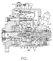
- the apparatus comprises a multipart housing 10 which includes a sleeve 11 defining a bore in which is mounted a rotary cylindrical distributor member 12.
- the distributor member 12 projects from the sleeve 11 and is provided with a transverse bore 13 in which is mounted a pair of plungers 14.
- the bore 13 communicates with an axial passage 15 formed in the distributor member and which connects with a delivery passage 16 terminating on the periphery of the distributor member in an axial groove.
- the inlet passages l8 communicate with a circumferential groove l9 which is formed in the peripheral surface of the sleeve ll and this communicates by way of an on/off valve 20, with the outlet of a fuel supply pump which is generally indicated at 2l.
- the supply pump draws fuel from an inlet not shown and its output pressure is controlled by a valve also not shown, so that the pressure varies in accordance with the speed at which the pump is driven.
- the rotary part of the supply pump 2l is carried on a drive shaft 22 which is journalled in the housing and is in use driven in timed relationship with the associated engine.
- the drive shaft mounts a dished gear wheel 23 and has an enlarged head portion 24 which surrounds the end of the distributor l2.
- the head portion 24 defines a pair of slots 25 in which are located shoes 26 which at their inner ends engage the plungers l4 respectively and which at their outer ends are provided with grooves which carry rollers 27.
- the shoes and rollers constitute cam followers.
- located in the slots 25 are drive plates 28 which are connected to the distributor member and the drive plates couple the distributor member to the drive shaft but at the same time, allow axial movement of the distributor member.
- the internal surface 24A of the enlarged portion 24 of the drive shaft is flared outwardly and the shoes 28 are provided with complementary surfaces 26A whereby the extent of outward movement of the plungers l4 will depend upon the axial setting of the distributor member.
- the drive shaft defines a chamber in which is located a coiled compression spring 29 which acts upon the adjacent end of the distributor member to urge it towards the right as seen in the drawing.
- a chamber 30 is defined in part by the end surface of the distributor member and in part by a cover 3l, the cover having a skirt portion which locates over the reduced end portion of the sleeve ll.
- a fluid seal is defined between the cover 3l and the sleeve whereby fuel under pressure in the groove l9 cannot enter into the chamber except by means to be described.
- the rollers 27 engage the internal peripheral surface of an angularly adjustable cam ring 32 on the internal peripheral surface of which are formed pairs of cam lobes.
- the lobes are positioned such that inward movement of the plungers can only take place whilst the groove at the outer end of the passage l6 is in communication with an outlet l7.
- fuel is supplied to the bore l3 and the plungers l4 are moved outwardly.
- the extent of outward movement of the plungers is limited by the abutment of the surfaces 26A on the shoes 26 with the flared surface 24A defined by the enlarged portion 24 of the drive shaft.
- the axial setting of the distributor member therefore determines the amount by which the plungers l4 can move outwardly and thereby the amount of fuel which is delivered by the apparatus at each delivery stroke. In the example as the distributor member is moved towards the right the amount of fuel which is delivered to the associated engine increases.
- a passage 33 which opens into the chamber 30 at one end and which at its other end, communicates with a port 34 on the periphery of the distributor member.
- an axially movable sleeve 35 mounted about the portion of the distributor member between the sleeve ll and the drive plate 28 is an axially movable sleeve 35. This is coupled to a governor mechanism to be described.
- a further passage 37 is formed in the distributor member and at one end communicates with the chamber 30. The other end of the passage 37 communicates with a radially disposed drilling 38 the ends of which open onto the periphery of the distributor member at a position to register with a port 39 formed in the sleeve and communicating with the aforesaid groove l9.
- the port 34 constitutes a variable orifice of a fluid potentiometer the fixed orifice of which is constituted by the drilling 38 and the port 39.
- the governor means comprises a centrifugal weight unit 40 the cage 4l of which is secured to an end face of a gear wheel 42 mounted about a shaft 43.
- the teeth of the gear wheel 42 mesh with the teeth of the gear wheel 23 and since the wheel 42 is smaller than the wheel 23 the cage will be driven at a speed greater than that of the drive shaft 22.
- the shaft 43 carries an axially movable sleeve 44 which is provided with a flange engaged by the toe portions of the weights 45. As the speed increases the weights move outwardly and thereby impart axial movement to the sleeve 44. As shown the sleeve and the weight unit are shown in the rest position. However, the sleeve 35 together with the remaining portion of the governor mechanism are shown in an engine idling position.
- the governor mechanism further includes a first pivotal lever 46 and this is pivotally mounted intermediate its ends about a pivot 47 carried by the housing.
- One end of the lever 46 mounts a projection 53 which is engaged within a recess in the sleeve 35 and the other end of the lever 46 is connected to one end of a coiled tension spring 57 which constitutes the governor spring.
- the other end of the spring 57 is connected to an arm 58 which can be adjusted by the engine operator, to determine the force exerted by the spring 57 on the lever 46.
- the sleeve 44 which.
- the governor mechanism includes a second lever 50 which is pivotally mounted at one end about an axis indicated at 5l, in the housing.
- the upper end of the lever 50 extends into a slot 52 which is formed in a plate member 53A secured within the housing.
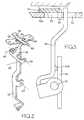
- the lever 50 intermediate its ends, is provided with a projection 54A which is engageable by the upper end of the lever 46.
- the projection is shown in Figure 3 and as will be seen, it is closer to the pivot axis 5l than to the opposite end of the lever which is slidable within the slot 52.
- the projection 54A acts to limit the movement of the lever 46 under the action of the spring 57 and it therefore serves to determine the maximum amount of fuel which can be supplied by the apparatus to the associated engine.
- the position of the lever 50 is adjustable and for this purpose there is provided a third lever 54 which intermediate its ends is secured as by welding or a rivet, to a cylindrical guide piece 55 slidable within the slot 52.
- the guide piece 55 is engaged by the upper end of the lever 50 and the outer ends of the lever 54 are turned downwardly to define projections 59, 60 respectively.
- the projections 59, 60 engage pegs 6l, 62 respectively which are mounted on respective abutment plates 63 and these are engaged by respective coiled compression springs 64, 65.
- the pegs 6l, 62 are movable against the action of the springs 64, 65 respectively by fluid pressure operable devices 66, 67 respectively.
- the device 66 comprises a fluid pressure operable piston 68 slidable within a cylinder the closed end of which is connected to the outlet of the supply pump 2l.
- the piston 68 has an integral tubular push piece 69 which engages the abutment plate 63 and as the outlet pressure of the supply pump increases the piston will move the abutment plate 63 and the peg 6l against the action of the spring 64.
- lever 54 will tend to pivot about the point of contact between the peg 62 and the projection 60 although the movement of the lever will be guided by the guide piece 55.
- the guide piece however will move downwardly as shown in Figure 4 to permit further anticlockwise movement of the lever 50 and thereby anticlockwise movement of the lever 46 under the action of the governor spring 57.
- the maximum amount of fuel which can be supplied to the engine will therefore be increased.
- the fluid pressure operable device 67 is not shown in its entirety but it includes a diaphragm one side of which is subjected to the pressure in the air inlet manifold of the associated engine.
- the diaphragam is coupled to a push pin 70 which engages a slidable push piece 7l engaging the respective abutment plate 63.
- the diaphragm will urge the abutment plate 63 downwardly against the action of the spring 65 and the lever 54 will pivot to permit an increase in the maximum amount of fuel which can be supplied to the associated engine.
- piston 68 and the diaphragm may effect movement of the lever at the same time but the practical effect is that the amount of fuel which can be supplied to the engine will increase in accordance with the engine speed and also the pressure in the air inlet manifold of the engine.
- the point of contact of the lever 46 with the projection 54A is close to the pivot axis 5l of the lever 50 whereas the point of contact of the guide piece 55 is some distance removed from the pivot axis 5l.
- the force acting on the guide piece 55 due to the governor spring is considerably reduced.
- the reaction force which has to be developed by the springs 64, 65 is further reduced by the lever ratio produced by the lever 54 and the springs 64, 65 can be sufficiently strong to withstand the reaction forces thereon due to the governor spring while at the same time the fluid pressure operable devices 66, 67 do not have to be large to effect movement of the respective pegs 6l, 62 against the action of the springs.
- the sleeve 35 may be mounted about a cylindrical member which is coupled to the distributor member at its end remote from th drive shaft as is shown in Figure 4 of the specification of GB 2069722B.
Landscapes
- Engineering & Computer Science (AREA)
- Chemical & Material Sciences (AREA)
- Combustion & Propulsion (AREA)
- Mechanical Engineering (AREA)
- General Engineering & Computer Science (AREA)
- High-Pressure Fuel Injection Pump Control (AREA)
Claims (4)
- Eine Kraftstoffeinspritzungs-Pumpeinrichtung, mit einem in Drehrichtung und in axialer Richtung beweglichen Verteilerelement (12), das einen durch Nockenerhebungen auf der Innenseite eines Nockenrings (32) betätigbaren Pumpkolben (14) trägt, geneigten Flächen (24A, 26A), die so betätigbar sind, daß sie die Auswärtsbewegung des Kolbens (14) begrenzen, wobei die axiale Position des Verteilerelementes (12) das Ausmaß der Auswärtsbewegung festlegt, einer Kammer (30), an die mit Druck beaufschlagte Flüssigkeit geliefert werden kann, um das Verteilerelement (12) gegen die Wirkung einer Feder (29) zu bewegen, einer Buchse (35), die axial beweglich ist, um den Druck der Flüssigkeit in der Kammer (30) festzulegen, einem ersten Schwenkhebel (46), der mit einem Ende der Buchse (35) gekoppelt ist, einer elastischen Einrichtung (57), die auf den Hebel (46) in einer Richtung wirkt, um den Hebel und die Buchse zwangsläufig so zu bewegen, daß die von der Einrichtung gelieferte Kraftstoffmenge erhöht wird, einer Reglereinrichtung (40), die entgegen der elastischen Einrichtung auf den Hebel (46) wirkt, und einer Anschlageinrichtung, die so betätigbar ist, daß sie die von der Einrichtung höchstens lieferbare Kraftstoffmenge begrenzt, dadurch gekennzeichnet, daß die Anschlageinrichtung einen zweiten Hebel (50), der an einem Ende angelenkt ist und zwischen seinen beiden Enden mit dem anderen Ende des ersten Hebels (46) in Eingriff gelangen kann, und einen Anschlag (55), der mit dem anderen Ende des zweiten Hebels (50) in Eingriff gelangen kann, umfaßt, wobei der Anschlag (55) zwischen den Enden eines dritten Hebels (54) angebracht ist, wobei die Enden des dritten Hebels jeweils mit einer durch den Fluiddruck betätigbaren Einrichtung (66, 67) verbunden sind.
- Eine Einrichtung gemäß Anspruch 1, dadurch gekennzeichnet, daß der Anschlag (55) eine zylindrische Form besitzt und in einem Schlitz (52) verschiebbar ist, der in einem am Gehäuse (10) der Einrichtung befestigten Element (53A) ausgebildet ist.
- Eine Einrichtung gemäß Anspruch 1, dadurch gekennzeichnet, daß sich der Berührungspunkt zwischen dem ersten und dem zweiten Hebel (46, 50) in der Nähe der Schwenkachse (51) des zweiten Hebels (50) befindet.
- Eine Einrichtung gemäß Anspruch 1, in der die durch den Fluiddruck betätigbare Einrichtung (66) einen federbelasteten Kolben (68) umfaßt, der einem von der Motordrehzahl abhängigen Fluiddruck unterworfen ist, und in der die durch den Fluiddruck betätigbare Einrichtung (67) eine auf den Luftdruck ansprechende Membran enthält.
Applications Claiming Priority (2)
| Application Number | Priority Date | Filing Date | Title |
|---|---|---|---|
| GB8809270 | 1988-04-20 | ||
| GB888809270A GB8809270D0 (en) | 1988-04-20 | 1988-04-20 | Fuel pumping apparatus |
Publications (3)
| Publication Number | Publication Date |
|---|---|
| EP0338708A2 EP0338708A2 (de) | 1989-10-25 |
| EP0338708A3 EP0338708A3 (en) | 1990-05-16 |
| EP0338708B1 true EP0338708B1 (de) | 1992-09-16 |
Family
ID=10635479
Family Applications (1)
| Application Number | Title | Priority Date | Filing Date |
|---|---|---|---|
| EP19890303495 Expired EP0338708B1 (de) | 1988-04-20 | 1989-04-10 | Kraftstoffpumpenvorrichtung |
Country Status (4)
| Country | Link |
|---|---|
| EP (1) | EP0338708B1 (de) |
| DE (1) | DE68902862T2 (de) |
| ES (1) | ES2035554T3 (de) |
| GB (1) | GB8809270D0 (de) |
Families Citing this family (1)
| Publication number | Priority date | Publication date | Assignee | Title |
|---|---|---|---|---|
| CN120402266B (zh) * | 2025-05-20 | 2026-01-27 | 浙江巴腾动力系统有限公司 | 一种增加寒冷环境预热效率的柴油泵 |
Family Cites Families (5)
| Publication number | Priority date | Publication date | Assignee | Title |
|---|---|---|---|---|
| US4120275A (en) * | 1975-06-28 | 1978-10-17 | Diesel Kiki Co., Ltd. | Engine fuel injection pump governor |
| GB1546078A (en) * | 1975-07-05 | 1979-05-16 | Lucas Industries Ltd | Fuel pumping apparatus |
| GB2069722B (en) * | 1980-02-16 | 1983-07-13 | Lucas Industries Ltd | Fuel injection pumping apparatus |
| JPS56163631U (de) * | 1980-05-06 | 1981-12-04 | ||
| DE3506041A1 (de) * | 1985-02-21 | 1986-08-21 | Robert Bosch Gmbh, 7000 Stuttgart | Kraftstoffeinspritzpumpe fuer brennkraftmaschinen |
-
1988
- 1988-04-20 GB GB888809270A patent/GB8809270D0/en active Pending
-
1989
- 1989-04-10 EP EP19890303495 patent/EP0338708B1/de not_active Expired
- 1989-04-10 DE DE1989602862 patent/DE68902862T2/de not_active Expired - Fee Related
- 1989-04-10 ES ES89303495T patent/ES2035554T3/es not_active Expired - Lifetime
Also Published As
| Publication number | Publication date |
|---|---|
| ES2035554T3 (es) | 1993-04-16 |
| GB8809270D0 (en) | 1988-05-25 |
| DE68902862T2 (de) | 1993-01-07 |
| EP0338708A2 (de) | 1989-10-25 |
| EP0338708A3 (en) | 1990-05-16 |
| DE68902862D1 (de) | 1992-10-22 |
Similar Documents
| Publication | Publication Date | Title |
|---|---|---|
| CA1125120A (en) | Liquid fuel injection pumping apparatus | |
| US4224916A (en) | Timing control for fuel injection pump | |
| US4098249A (en) | Fuel injection pumping apparatus | |
| US4050433A (en) | Liquid fuel pumping apparatus | |
| US4920940A (en) | Fuel pumping apparatus | |
| US4362141A (en) | Fuel injection pumping apparatus | |
| US4214564A (en) | Fuel injection pumping apparatus | |
| CA1056674A (en) | Fuel injection pumping apparatus | |
| US4397615A (en) | Fuel injection pumping apparatus | |
| EP0338708B1 (de) | Kraftstoffpumpenvorrichtung | |
| US4242059A (en) | Fuel pumping apparatus | |
| US4406264A (en) | Governor for engines | |
| US4419054A (en) | Liquid fuel injection pumping apparatus | |
| US4764092A (en) | Liquid fuel injection pump | |
| US4055387A (en) | Liquid fuel injection pumping apparatus | |
| US4362140A (en) | Liquid fuel injection pumps | |
| US5044893A (en) | Fuel injection apparatus | |
| US4457277A (en) | Fuel injection pumping apparatus | |
| US5207202A (en) | Fuel pumping apparatus | |
| US4050437A (en) | Liquid fuel injection pumping apparatus | |
| US4759694A (en) | Liquid fuel pumping apparatus | |
| US4358256A (en) | Fuel injection pumping apparatus | |
| US5203303A (en) | Fuel pumping apparatus | |
| US4441474A (en) | Fuel injection pumping apparatus | |
| US4348995A (en) | Fuel pumping apparatus |
Legal Events
| Date | Code | Title | Description |
|---|---|---|---|
| PUAI | Public reference made under article 153(3) epc to a published international application that has entered the european phase |
Free format text: ORIGINAL CODE: 0009012 |
|
| AK | Designated contracting states |
Kind code of ref document: A2 Designated state(s): DE ES FR GB IT |
|
| PUAL | Search report despatched |
Free format text: ORIGINAL CODE: 0009013 |
|
| AK | Designated contracting states |
Kind code of ref document: A3 Designated state(s): DE ES FR GB IT |
|
| 17P | Request for examination filed |
Effective date: 19901109 |
|
| 17Q | First examination report despatched |
Effective date: 19910704 |
|
| GRAA | (expected) grant |
Free format text: ORIGINAL CODE: 0009210 |
|
| AK | Designated contracting states |
Kind code of ref document: B1 Designated state(s): DE ES FR GB IT |
|
| ITF | It: translation for a ep patent filed | ||
| REF | Corresponds to: |
Ref document number: 68902862 Country of ref document: DE Date of ref document: 19921022 |
|
| ET | Fr: translation filed | ||
| PGFP | Annual fee paid to national office [announced via postgrant information from national office to epo] |
Ref country code: GB Payment date: 19930331 Year of fee payment: 5 |
|
| PGFP | Annual fee paid to national office [announced via postgrant information from national office to epo] |
Ref country code: FR Payment date: 19930408 Year of fee payment: 5 |
|
| PGFP | Annual fee paid to national office [announced via postgrant information from national office to epo] |
Ref country code: ES Payment date: 19930415 Year of fee payment: 5 |
|
| REG | Reference to a national code |
Ref country code: ES Ref legal event code: FG2A Ref document number: 2035554 Country of ref document: ES Kind code of ref document: T3 |
|
| PGFP | Annual fee paid to national office [announced via postgrant information from national office to epo] |
Ref country code: DE Payment date: 19930421 Year of fee payment: 5 |
|
| PLBE | No opposition filed within time limit |
Free format text: ORIGINAL CODE: 0009261 |
|
| STAA | Information on the status of an ep patent application or granted ep patent |
Free format text: STATUS: NO OPPOSITION FILED WITHIN TIME LIMIT |
|
| 26N | No opposition filed | ||
| PG25 | Lapsed in a contracting state [announced via postgrant information from national office to epo] |
Ref country code: GB Effective date: 19940410 |
|
| PG25 | Lapsed in a contracting state [announced via postgrant information from national office to epo] |
Ref country code: ES Free format text: LAPSE BECAUSE OF NON-PAYMENT OF DUE FEES Effective date: 19940411 |
|
| GBPC | Gb: european patent ceased through non-payment of renewal fee |
Effective date: 19940410 |
|
| PG25 | Lapsed in a contracting state [announced via postgrant information from national office to epo] |
Ref country code: FR Effective date: 19941229 |
|
| PG25 | Lapsed in a contracting state [announced via postgrant information from national office to epo] |
Ref country code: DE Effective date: 19950103 |
|
| REG | Reference to a national code |
Ref country code: FR Ref legal event code: ST |
|
| REG | Reference to a national code |
Ref country code: ES Ref legal event code: FD2A Effective date: 19990503 |
|
| PG25 | Lapsed in a contracting state [announced via postgrant information from national office to epo] |
Ref country code: IT Free format text: LAPSE BECAUSE OF NON-PAYMENT OF DUE FEES;WARNING: LAPSES OF ITALIAN PATENTS WITH EFFECTIVE DATE BEFORE 2007 MAY HAVE OCCURRED AT ANY TIME BEFORE 2007. THE CORRECT EFFECTIVE DATE MAY BE DIFFERENT FROM THE ONE RECORDED. Effective date: 20050410 |