EP0338167A1 - Driving device for the simultaneous drive of two parallel screw and nut systems - Google Patents
Driving device for the simultaneous drive of two parallel screw and nut systems Download PDFInfo
- Publication number
- EP0338167A1 EP0338167A1 EP88400933A EP88400933A EP0338167A1 EP 0338167 A1 EP0338167 A1 EP 0338167A1 EP 88400933 A EP88400933 A EP 88400933A EP 88400933 A EP88400933 A EP 88400933A EP 0338167 A1 EP0338167 A1 EP 0338167A1
- Authority
- EP
- European Patent Office
- Prior art keywords
- planetary
- motor
- wheels
- coupled
- screw
- Prior art date
- Legal status (The legal status is an assumption and is not a legal conclusion. Google has not performed a legal analysis and makes no representation as to the accuracy of the status listed.)
- Withdrawn
Links
Images
Classifications
-
- B—PERFORMING OPERATIONS; TRANSPORTING
- B21—MECHANICAL METAL-WORKING WITHOUT ESSENTIALLY REMOVING MATERIAL; PUNCHING METAL
- B21B—ROLLING OF METAL
- B21B31/00—Rolling stand structures; Mounting, adjusting, or interchanging rolls, roll mountings, or stand frames
- B21B31/16—Adjusting or positioning rolls
- B21B31/20—Adjusting or positioning rolls by moving rolls perpendicularly to roll axis
- B21B31/22—Adjusting or positioning rolls by moving rolls perpendicularly to roll axis mechanically, e.g. by thrust blocks, inserts for removal
- B21B31/24—Adjusting or positioning rolls by moving rolls perpendicularly to roll axis mechanically, e.g. by thrust blocks, inserts for removal by screws
Landscapes
- Engineering & Computer Science (AREA)
- Mechanical Engineering (AREA)
- Transmission Devices (AREA)
Abstract
Description
Il existe de nombreux dispositifs mécaniques impliquant le déplacement paralléle et simultané de deux points sur une même amplitude. C'est, notamment, le cas du rouleau supérieur d'un train de laminage qui doit être déplacé parallèlement à lui-même et à un axe fixe pour prendre en compte l'épaisseur à obtenir du métal en feuille et asservir cette épaisseur à une consigne. Ce rouleau doit être également déplacé en basculement pour permettre de règler l'épaisseur, ou d'en maîtriser les variations d'un bord à l'autre de la bande. On sait en effet qu'une bande plus amincie sur un bord que sur l'autre, du fait d'un pincement plus important du métal à une extrémité axiale des rouleaux de laminage, présente de ce côté un "bord long" qu'il convient de supprimer rapidement en agissant sur le basculement du rouleau supérieur.There are many mechanical devices involving the parallel and simultaneous movement of two points on the same amplitude. This is, in particular, the case of the upper roller of a rolling train which must be moved parallel to itself and to a fixed axis to take into account the thickness to be obtained from the sheet metal and to control this thickness to a instructions. This roller must also be moved in tilt to allow the thickness to be adjusted, or to control variations from one edge to the other of the strip. We know in fact that a strip thinner on one edge than on the other, due to a greater pinching of the metal at an axial end of the rolling rolls, has on this side a "long edge" that it should be removed quickly by acting on the tilting of the upper roller.
Ces dispositifs connus sont essentiellement de deux types à savoir, des systèmes hydrauliques du genre vérin et dont les chambres hydrauliques sont alimentées par des servo-valves pilotées par des dispositifs électroniques d'asservissement, ou des systèmes mécaniques (système vis-écrou, roue et vis sans fin...) dans lesquels chacun des systèmes est entraîné par un moteur séparé, un système électronique de couplage des moteurs permettant d'obtenir l'asservissement désiré.These known devices are essentially of two types, namely, hydraulic systems of the jack type and whose hydraulic chambers are supplied by servo-valves controlled by electronic servo devices, or mechanical systems (screw-nut system, wheel and worm ...) in which each of the systems is driven by a separate motor, an electronic motor coupling system allowing the desired control to be obtained.
Les inconvénients de ces dispositifs connus résident dans leur complexité, la nécessité d'une maintenance de haut niveau, une fiabilité dépendant de celle des composants électroniques et un coût très élevé.The disadvantages of these known devices lie in their complexity, the need for high-level maintenance, reliability depending on that of the components. electronics and a very high cost.
La présente invention entend remédier à ces inconvénients en proposant un matériel mécanique robuste et simple supprimant la nécessité d'un asservissement complexe fragile et coûteux, et qui peut être commandé aisément soit manuellement, soit automatiquement, soit enfin de manière mixte.The present invention intends to remedy these drawbacks by proposing a robust and simple mechanical material eliminating the need for a fragile and costly complex control system, which can be easily controlled either manually, or automatically, or finally in a mixed manner.
A cet effet elle a donc pour objet un dispositif d'entraînement simultané en translation d'amplitude égale, dans un même sens ou en sens opposé des deux vis de deux systèmes vis-écrou parallèles à écrous fixes, dans lequel chaque vis est accouplée en rotation à l'un des arbres de roue planétaire d'un mécanisme constitué par deux trains d'engrenages planétaires dont le châssis porte-satellites de chacun d'eux est accouplé à l'arbre de sortie d'un premier moteur, de manière à tourner de la même amplitude et dans le même sens, l'autre arbre de roue planétaire de chacun des trains planétaires étant accouplé à son homologue pour tourner de la même amplitude et en sens inverse sous l'effet d'un second moteur d'entraînement de l'un d'eux.To this end it therefore relates to a device for simultaneously driving in translation of equal amplitude, in the same direction or in the opposite direction of the two screws of two parallel screw-nut systems with fixed nuts, in which each screw is coupled in rotation of one of the planetary wheel shafts of a mechanism consisting of two planetary gear trains, the planet carrier chassis of each of which is coupled to the output shaft of a first motor, so as to rotate the same amplitude and in the same direction, the other planetary wheel shaft of each of the planetary trains being coupled to its counterpart to rotate the same amplitude and in the opposite direction under the effect of a second drive motor from one of them.
Dans un mode préféré de réalisation, les axes de rotation des roues planétaires, du châssis porte-satellites et des moteurs d'entraînement sont parallèles et parallèles aux vis, l'accouplement de chacun des châssis à l'arbre du premier moteur étant réalisé au moyen de roues dentées identiques portées par chaque châssis et engrènant avec un pignon calé sur l'arbre du premier moteur, tandis que l'accouplement des deux arbres de planétaires étant réalisé par engrénement de deux roues dentées identiques calées sur chacun d'eux, leur entraînement est assuré par l'engrènement de l'une d'elles avec un pignon calé sur l'arbre du second moteur.In a preferred embodiment, the axes of rotation of the planetary wheels, of the planet carrier chassis and of the drive motors are parallel and parallel to the screws, the coupling of each of the chassis to the shaft of the first motor being carried out at by means of identical toothed wheels carried by each chassis and meshing with a pinion wedged on the shaft of the first motor, while the coupling of the two planetary shafts being achieved by meshing two identical toothed wheels wedged on each of them, their drive is ensured by the engagement of one of them with a pinion wedged on the shaft of the second motor.
Chaque train planétaire est porté par la vis auquel il est accouplé. Pour éviter, lors de la manoeuvre en sens opposé de chaque vis, une perte d'engrènement entre les roues dentées d'accouplement des porte-satellites entre eux et au moteur correspondant et entre les roues d'accouplement des autres arbres planétaires, chaque roue et pignon participant à ces liaisons est d'une épaisseur suffisante pour prendre en compte les différences d'altitude des trains d'engrenage.Each planetary gear is carried by the screw to which it is coupled. To avoid, when operating in the opposite direction of each screw, a loss of meshing between the toothed wheels for coupling the planet carrier between them and to the corresponding motor and between the coupling wheels of the other planetary shafts, each wheel and pinion participating in these connections is of sufficient thickness to take into account the differences in altitude of the gear trains.
On utilisera de manière avantageuse des trains planétaires dont les arbres de planétaire coaxiaux sont en outre concentriques.Planetary trains, the coaxial planetary shafts of which are also concentric, will be advantageously used.
Enfin on pourra prévoir que chacun des moteurs mis en oeuvre soit commandé automatiquement en fonction de paramètres relevés sur, dans le cas d'un laminoir, la tôle sortant de ce laminoir, ou soit piloté manuellement par un opérateur.On notera que le principal avantage du dispositif selon l'invention réside dans le découplement total entre la commande du déplacement parallèlement à elles-mêmes des extrémités de vis et la commande en sens contraire symétrique par rapport à un point fixe de ces extrémités. Il en résulte un dispositif d'asservissement extrêmement simple et beaucoup plus sûr que ceux mis en oeuvre jusqu'à présent.Finally, provision could be made for each of the motors used to be automatically controlled as a function of parameters taken from, in the case of a rolling mill, the sheet leaving this rolling mill, or to be controlled manually by an operator. It will be noted that the main advantage of the device according to the invention lies in the total decoupling between the control of the displacement of the screw ends parallel to themselves and the control in opposite direction symmetrical with respect to a fixed point of these ends. The result is an extremely simple servo device and much safer than those implemented so far.
L'invention sera mieux comprise au cours de la description donnée ci-après à titre d'exemple purement indicatif et non limitatif qui permettra d'en dégager les avantages et les caractéristiques secondaires.The invention will be better understood during the description given below by way of purely indicative and nonlimiting example which will make it possible to identify the advantages and the secondary characteristics thereof.
Il sera fait référence aux dessins annexés dans lesquels :
- - la figure 1 est un schéma du dispositif selon l'invention,
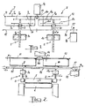
- - la figure 2 illustre une application de ce dispositif au serrage d'un laminoir.
- FIG. 1 is a diagram of the device according to the invention,
- - Figure 2 illustrates an application of this device to the clamping of a rolling mill.
En se reportant à ces figures, on voit deux systèmes vis-écrou parallèles 1 et 2, chaque vis 1a, 2a tournant dans l'écrou fixe 1b, 2b correspondant, appartenant à un bâti non représenté. Sur la figure 2 on voit que les extrémités des vis 1a; 2a sont attelées aux paliers, mobiles verticalement dans un bâti non représenté, 3 et 4, d'un rouleau supé rieur 5 de laminoir dont le rouleau inférieur 6 est fixe. On voit donc qu'en vissant ou dévissant les vis 1a, 2a dans les écrous 1b, 2b, on déplace les paliers 3 et 4. Les vis étant supposées de même dimension et de même pas, leur vissage ou dévissage simultané de même amplitude provoque un déplacement du rouleau 5 parallèle à lui-même. En revanche, le vissage de l'une simultanément au dévissage de l'autre d'une même amplitude entraîne un pivotement du rouleau 5 autour d'un axe 0 perpendiculaire à son axe de rotation, dans sa partie médiane.Referring to these figures, we see two parallel screw-
Chacune des vis 1a, 2a est accouplée à l'une des roues planétaires 7a, 8a d'un train d'engrenages planétaires 7 et 8, dont l'autre roue planétaire est référencée 7b, 8b et dont les pignons satellites 7c, 7d, 8c, 8d sont portés par un chassis porte-satellites7e, 8e. Les trains planétaires 7 et 8 ont la particularité d'avoir leurs axes de roues planétaires concentriques. Ainsi l'un des axes étant constitué par les vis 1a, 2a l'autre, accouplé aux roues 7b, 8b est constitué par une douille 9, 10 entourant les vis. Ces trains particuliers sont connus et sont commercialisés depuis de nombreuses années par la Demanderesse, en tant que module épicycloïdal ou différentiel.Each of the screws 1 a , 2 a is coupled to one of the planetary wheels 7 a , 8 a of a
Dans leur utilisation conforme à l'invention, chaque châssis 7e 8e de module différentiel est équipé d'une roue dentée 11, 12 identique, qui coopère directement avec un pignon 13 de sortie d'un groupe moto-réducteur 14. En outre, chaque douille planétaire 9, 10 est équipée d'une roue dentée 15,16 identique et engrenant avec l'autre, l'une de ces roues, ici 16, étant entraînée par le pignon 17 d'un second moteur 18 ou groupe moto-réducteur.In their use in accordance with the invention, each chassis 7 e 8 e of differential module is equipped with an
Le fonctionnement du dispositif selon l'invention s'opère de la manière suivante :The operation of the device according to the invention operates as follows:
Lorsque l'on veut obtenir le vissage simultané des deux vis 1a, 2a dans les écrous 1b, 2b on commande la rotation du pignon 13 dans le sens approprié par alimentation du groupe moteur 14. Cette rotation engendre la rotation des deux porte-satellites 7e et 8e dans le même sens. Le groupe 18 n'étant pas alimenté, le pignon 17 est immobile ainsi que les roues 15 et 16 et les planétaires correspondants 7b, 8b. Dans ces conditions la rotation des chassis 7e, 8e entraîne la rotation des planétaires 7a, 8a donc le vissage (ou dévissage) des vis 1a, 2a dans les écrous correspondants, et ce à la même vitesse donc avec la même amplitude comme le montre un calcul simple. Le rouleau 5, dans le cas d'application de la figure 2, est donc déplacé parallèlement à lui-même, par rapport au rouleau 6. On comprend qu'un asservissement simple de la position du rouleau 5 par rapport au rouleau 6 puisse être obtenu à partir d'un capteur de l'épaisseur de produit laminé que l'on veut obtenir.When one wants to obtain the simultaneous screwing of the two screws 1 a , 2 a in the nuts 1 b , 2 b, the rotation of the
Si en revanche, il faut procéder au réglage de l'inclinaison de l'axe du rouleau 5 sur celui du rouleau 6 pour, par exemple, corriger un bord long de tôle, on agira sur le moteur 18 dont la rotation dans un sens approprié, entraîne la rotation, par le pignon 17 des roues 15 et 16 en sens contraire. En supposant les châssis porte satellites 7e 8e immobiles en rotation, la rotation des roues 15 et 16, donc des planétaires 7b et 8b entraîne la rotation des planétaires 7a, 8a dans le rapport de réduction défini par le rapport de réduction entre d'une part, les roues 7b, 7d ou 8b, 8d et les roues 7c, 7a ou 8c, 8a. Les vis sont alors commandées en sens contraire et l'une se visse pendant que l'autre se dévisse de la même amplitude, comme le montre également le calcul. Dans ce cas, le rouleau 5 tourne autour d'un axe centré en 0 sur la figure 2. Au droit de ce point, il y a conservation de l'épaisseur (ou de la distance) séparant les deux rouleaux telle que définie par le premier réglage asservi, au moyen du moteur 14. La commande du moteur 18 entraîne donc un balancement différent du serrage des rouleaux autour d'une valeur moyenne déterminée. On rappellera qu'il n'était pas possible d'obtenir une telle disposi tion avec les dispositifs antérieurs dans lesquels le réglage de l'inclinaison du rouleau supérieur entraîne une réaction sur le réglage de l'épaisseur, du fait de l'indépendance mécanique des deux moteurs de commande des vis. On perçoit donc la complexité de l'asservissement qu'il faut prévoir pour obtenir une réaction adéquate lors de la variation de l'un ou l'autre (épaisseur ou existence d'un bord long par exemple) des paramètres surveillés.If on the other hand, it is necessary to adjust the inclination of the axis of the roller 5 to that of the
Dans l'invention en revanche, il n'y a pas besoin de coupler le moteur 14 au moteur 18 pour que le dispositif donne pleinement satisfaction. Le moteur 18 peut d'ailleurs être commandé par un opérateur qui surveille visuellement le produit issu du laminoir et commande les corrections de pincement en fonction de la qualité du produit qu'il apprécie; de son coté, le moteur 14 est piloté par une jauge qui compare l'épaisseur réelle du produit avec une valeur de consigne. On peut, par ailleurs, prévoir un asservissement du fonctionnement du moteur 18 à des capteurs de la différence d'épaisseur du produit le long de ses rives, qui serait maintenue autour de la valeur nulle dans une certaine plage de tolérances.In the invention, on the other hand, there is no need to couple the
On notera enfin que les amplitudes de déplacement dans le cas du réglage par le moteur 18 sont très petites. Comme, par construction, les trains d'engrenages 7 et 8 sont uniquement supportés par les vis 1a et 2a, il se produit, lors de la commande du moteur 18, un décalage vertical entre eux. Pour éviter une perte d'engrènement entre les pignons et les roues dentées, il faudra prévoir que les diverses épaisseurs E₁, E₂, E₃ et E₄ de ces organes soient suffisantes pour qu'il y ait toujours suffisamment de longueur de dent en prise et ainsi une bonne transmission des couples. On peut également prévoir que les moteurs 14 et 18 soient fixes sur un bâti et que les ensembles 7 et 8 se déplacent verticalement par rapport à eux. Dans ce cas, les pignons 13 et 17 auront une longueur de dent E₂, E₄ suffisante (dans le sens axial) pour être toujours en prise avec les roues, mobiles axialement du fait des deux mouvements possible des vis (ensemble ou en sens opposé). Les moteurs peuvent aussi être supportés par un bâti qui se déplace avec le point 0 du rouleau 5.Finally, note that the displacement amplitudes in the case of adjustment by the
L'invention trouve une application intéressante dans le domaine de la construction mécanique, notamment des trains de laminoir.The invention finds an interesting application in the field of mechanical construction, in particular rolling mill trains.
Claims (7)
Priority Applications (2)
| Application Number | Priority Date | Filing Date | Title |
|---|---|---|---|
| FR8700332A FR2609517B1 (en) | 1987-01-14 | 1987-01-14 | SIMULTANEOUS DRIVE DEVICE FOR TWO PARALLEL SCREW NUT SYSTEMS |
| EP88400933A EP0338167A1 (en) | 1988-04-18 | 1988-04-18 | Driving device for the simultaneous drive of two parallel screw and nut systems |
Applications Claiming Priority (1)
| Application Number | Priority Date | Filing Date | Title |
|---|---|---|---|
| EP88400933A EP0338167A1 (en) | 1988-04-18 | 1988-04-18 | Driving device for the simultaneous drive of two parallel screw and nut systems |
Publications (1)
| Publication Number | Publication Date |
|---|---|
| EP0338167A1 true EP0338167A1 (en) | 1989-10-25 |
Family
ID=8200379
Family Applications (1)
| Application Number | Title | Priority Date | Filing Date |
|---|---|---|---|
| EP88400933A Withdrawn EP0338167A1 (en) | 1987-01-14 | 1988-04-18 | Driving device for the simultaneous drive of two parallel screw and nut systems |
Country Status (1)
| Country | Link |
|---|---|
| EP (1) | EP0338167A1 (en) |
Citations (4)
| Publication number | Priority date | Publication date | Assignee | Title |
|---|---|---|---|---|
| DE345555C (en) * | 1921-01-04 | 1921-12-13 | Bauer Alfred | Central interlocking for the pressure spindles of rolling mills |
| DE430040C (en) * | 1925-04-10 | 1926-06-09 | Fried Krupp Grusonwerk Akt Ges | Device for adjusting the pressure spindles of rolling mills |
| US3415097A (en) * | 1966-08-18 | 1968-12-10 | Stephen W. Wheeler | Combination gage and guide control for strip mills |
| FR2609517A1 (en) * | 1987-01-14 | 1988-07-15 | Redex Sa | Device for simultaneously driving the screws of two parallel screw-nut systems |
-
1988
- 1988-04-18 EP EP88400933A patent/EP0338167A1/en not_active Withdrawn
Patent Citations (4)
| Publication number | Priority date | Publication date | Assignee | Title |
|---|---|---|---|---|
| DE345555C (en) * | 1921-01-04 | 1921-12-13 | Bauer Alfred | Central interlocking for the pressure spindles of rolling mills |
| DE430040C (en) * | 1925-04-10 | 1926-06-09 | Fried Krupp Grusonwerk Akt Ges | Device for adjusting the pressure spindles of rolling mills |
| US3415097A (en) * | 1966-08-18 | 1968-12-10 | Stephen W. Wheeler | Combination gage and guide control for strip mills |
| FR2609517A1 (en) * | 1987-01-14 | 1988-07-15 | Redex Sa | Device for simultaneously driving the screws of two parallel screw-nut systems |
Similar Documents
| Publication | Publication Date | Title |
|---|---|---|
| FR2672277A1 (en) | BRAKE COMPRISING A DEVICE FOR ADJUSTING THE ADJUSTABLE ELEMENTS OF A BRAKE CYLINDER. | |
| EP0074453B1 (en) | Method and apparatus for manufacturing spirally wound paper tubes, and tubes produced by such a method | |
| FR2599655A1 (en) | MOTOR TOOL FOR TIGHTENING SCREW JOINTS WITH A TORQUE LIMITING DEVICE | |
| FR2732638A1 (en) | CUTTING MODULE FOR BAND PRODUCT AND CUTTING DEVICE EQUIPPED WITH AT LEAST ONE SUCH MODULE | |
| FR2935672A1 (en) | Rear steering suspension arm for rear axle of motor vehicle, has turning actuator driving steering wheel swivel by gear comprising endless screw, where actuator has toothed sector centered on steering wheel swivel | |
| FR2713583A1 (en) | Track tension device. | |
| FR2540012A1 (en) | COLD ROLLER WITH NO PILGRIMS OPERATING CONTINUOUSLY | |
| FR3091847A1 (en) | SUPPORT DEVICE, CONTROL SYSTEM AND INSPECTION SYSTEM | |
| FR2692191A1 (en) | Pair of tensioning rollers, in particular for printing machines. | |
| EP0369862B1 (en) | Driving device for laminated glass calender driving rollers and calender equipped with this device | |
| EP0542610A1 (en) | Workpiece-supporting device for a bending machine | |
| FR2542604A1 (en) | TILT EXAMINATION CHASSIS | |
| EP0338167A1 (en) | Driving device for the simultaneous drive of two parallel screw and nut systems | |
| EP0084509B1 (en) | Reversible variable-speed drive mechanism for dough-laminator conveyors | |
| US4819507A (en) | Device for simultaneously driving the screws of two parallel screw-and-nut systems | |
| FR2609517A1 (en) | Device for simultaneously driving the screws of two parallel screw-nut systems | |
| FR2808728A1 (en) | DOUBLE-EFFECTIVE SPLIT DEVICE FOR OPENING A STRIP IN A ROTARY PRINTING MACHINE | |
| FR2460180A1 (en) | SIDE INDICATING DEVICE FOR EQUIPPING A SHEET METAL FORMING OR SHEARING MACHINE TOOL | |
| FR2897916A1 (en) | AUXILIARY STEERING DRIVE, SHAFT DISPLACEMENT DEVICE FOR THIS STEERING DRIVE, AND METHOD OF MOUNTING SUCH A DRIVE | |
| FR2498379A1 (en) | ORTHOGONAL AXIS ORIENTATION DEVICE, USE IN A HYPERFREQUENCY ANTENNA AND HYPERFREQUENCY ANTENNA COMPRISING SUCH A DEVICE | |
| EP0712769A1 (en) | Procedure and device for controlling trailer braking | |
| FR2550486A1 (en) | DIGITAL-CONTROLLED DISC CUTTING MACHINE AND METHOD OF ADJUSTING ITS CUTTING ARRANGEMENTS | |
| FR3005461A1 (en) | VARIABLE SYNCHRONIZED MOTORIZATION DEVICE FOR CONVEYORS | |
| FR2583732A1 (en) | LINEAR DRIVE UNIT USED ON THE TROLLEY OF A LIFTING APPARATUS. | |
| EP0857889B1 (en) | Bevel gear drive with a pair of gears with interchangeable gear ratio |
Legal Events
| Date | Code | Title | Description |
|---|---|---|---|
| PUAI | Public reference made under article 153(3) epc to a published international application that has entered the european phase |
Free format text: ORIGINAL CODE: 0009012 |
|
| 17P | Request for examination filed |
Effective date: 19880420 |
|
| AK | Designated contracting states |
Kind code of ref document: A1 Designated state(s): AT BE CH DE ES FR GB GR IT LI LU NL SE |
|
| 17Q | First examination report despatched |
Effective date: 19900904 |
|
| STAA | Information on the status of an ep patent application or granted ep patent |
Free format text: STATUS: THE APPLICATION IS DEEMED TO BE WITHDRAWN |
|
| 18D | Application deemed to be withdrawn |
Effective date: 19910830 |