EP0338145B1 - Foldable scaffolding unit - Google Patents
Foldable scaffolding unit Download PDFInfo
- Publication number
- EP0338145B1 EP0338145B1 EP88303486A EP88303486A EP0338145B1 EP 0338145 B1 EP0338145 B1 EP 0338145B1 EP 88303486 A EP88303486 A EP 88303486A EP 88303486 A EP88303486 A EP 88303486A EP 0338145 B1 EP0338145 B1 EP 0338145B1
- Authority
- EP
- European Patent Office
- Prior art keywords
- struts
- pair
- scaffolding unit
- bottom portion
- hook
- Prior art date
- Legal status (The legal status is an assumption and is not a legal conclusion. Google has not performed a legal analysis and makes no representation as to the accuracy of the status listed.)
- Expired - Lifetime
Links
- 210000000078 claw Anatomy 0.000 claims description 15
- 230000015572 biosynthetic process Effects 0.000 claims description 2
- 125000006850 spacer group Chemical group 0.000 description 5
- 238000010276 construction Methods 0.000 description 2
- 238000009434 installation Methods 0.000 description 2
- 238000009435 building construction Methods 0.000 description 1
- 230000005484 gravity Effects 0.000 description 1
Images



Classifications
-
- E—FIXED CONSTRUCTIONS
- E04—BUILDING
- E04G—SCAFFOLDING; FORMS; SHUTTERING; BUILDING IMPLEMENTS OR AIDS, OR THEIR USE; HANDLING BUILDING MATERIALS ON THE SITE; REPAIRING, BREAKING-UP OR OTHER WORK ON EXISTING BUILDINGS
- E04G5/00—Component parts or accessories for scaffolds
- E04G5/04—Means for fastening, supporting, or bracing scaffolds on or against building constructions
-
- E—FIXED CONSTRUCTIONS
- E04—BUILDING
- E04G—SCAFFOLDING; FORMS; SHUTTERING; BUILDING IMPLEMENTS OR AIDS, OR THEIR USE; HANDLING BUILDING MATERIALS ON THE SITE; REPAIRING, BREAKING-UP OR OTHER WORK ON EXISTING BUILDINGS
- E04G3/00—Scaffolds essentially supported by building constructions, e.g. adjustable in height
- E04G3/22—Scaffolds essentially supported by building constructions, e.g. adjustable in height supported by roofs or ceilings
-
- E—FIXED CONSTRUCTIONS
- E04—BUILDING
- E04G—SCAFFOLDING; FORMS; SHUTTERING; BUILDING IMPLEMENTS OR AIDS, OR THEIR USE; HANDLING BUILDING MATERIALS ON THE SITE; REPAIRING, BREAKING-UP OR OTHER WORK ON EXISTING BUILDINGS
- E04G5/00—Component parts or accessories for scaffolds
- E04G5/04—Means for fastening, supporting, or bracing scaffolds on or against building constructions
- E04G5/045—Means for fastening, supporting, or bracing scaffolds on or against building constructions for fastening scaffoldings on profiles, e.g. I or H profiles
Definitions
- the present invention relates to scaffolding, and more particularly to a foldable scaffolding unit for use in building construction, ship building or other construction work and provided with hook members on the rear side so that the gondola-like scaffolding unit may be suspended in a working position and may be folded into a compact size convenient to transport and to keep in storage.
- scaffolding is fixed or suspended on the working side of the construction to be worked on, on which scaffolding a workperson can stand.
- various conventional scaffoldings are composed of many single tubes joined together vertically and horizontally, and other parts which include relatively long parts with handrails. Due to the large number of components, the installation and dismantling of-the conventional scaffolding at the working site is laborious and time-consuming and hence expensive. Further, the conventional scaffolding is inconvenient to transport and to keep in storage.
- the present invention relates more particularly to a foldable scaffolding unit of the type comprising, a rectangular bottom portion; a pair of front struts each pivotally connected at one end to a respective one of a pair of front corners of said bottom portion; a pair of rear struts each pivotally connected at one end to a respective one of a pair of rear corners of said bottom portion; at least one handrail pivotally connected at opposite ends to a respective one of said front struts and the corresponding one of said rear struts; a pair of cross-struts each connected at opposite ends to a respective one of said front struts and to the corresponding one of said rear struts, each said cross-strut being foldable or adjustable in length; and a pivotally-connected extendable hook member.
- CH-A- 116763 discloses a foldable safety enclosure of this type which can be mounted on a windowsill, defining a working platform when open and is conveniently folded up for storage and transportation.
- the present invention is characterised in that the cross-struts are connected to the other ends of the respective front and rear struts, in that a pair of such hook members are provided, each attached to a respective one of said rear struts via a hinge having a pair of hinge plates pivotally connected together by a pivot pin, each said hook member including a claw, a screw bolt connected to said claw, a tube mounted on said screw bolt arid provided with a hook formation, and a nut threadably mounted on said screw bolt.
- the hook members are attached to the rear struts via the hinges, it is possible to install the scaffolding unit either at a right angle to the support or at a corner.
- the principle of the present invention is particularly useful when embodied in a scaffolding unit such as shown in Figures 1 and 2.
- the scaffolding unit includes four horizontal base bars 4 connected together into a rectangle so as to surround a rectangular bottom portion 5, a pair of relatively short front struts 2 each pivotally connected at one end to the respective front corner of the rectangular bottom portion 5, and a pair of relatively long rear struts 3 each pivotally connected at one end to the respective rear corner of the rectangular bottom portion 5.
- the principle of the present invention is particularly useful when embodied in a scaffolding unit such as shown in Figures 1 and 2.
- the scaffolding unit includes four horizontal base bars 4 connected together into a rectangle so as to surround a rectangular bottom portion 5, a pair of relatively short front struts 2 each pivotally connected at one end to the respective front corner of the rectangular bottom portion 5, and a pair of relatively long rear struts 3 each pivotally connected at one end to the respective rear corner of the rectangular bottom portion 5.
- Diagonal tie members 6 and a horizontal rail 7 are pivotally mounted between the front struts 2 so as to serve respectively as braces and a handrail.
- Pivotally connected to and extending between each of the front struts 2 and the corresponding rear struts 3 are a pair of horizontal rails 8, 9 which can serve as handrails.
- a pair of hangers or supports 10 are supported between an upper portion of each rear strut 3 and an upper portion of the corresponding front strut 2 and each hanger or support 10 is foldable each about an intermediate pivot a .
- the bottom portion 5 together with the front struts 2 are moved forwardly to form a gondola-type unit as shown in Figures 1 and 2.
- both the bottom portion 5 and the front struts 2 are pulled upwardly so that the entire scaffolding unit is folded into a compact size, as shown in Figure 3.
- a telescopic rod or chain may be used in place of the foldable support or hanger 10.
- FIGS 4 and 5 shown an attaching device and a hook member 19.
- An attaching device and hook member 19 is fixedly secured to the upper rear surface or upper side surface of each of the rear strut 3, and is connected to each rear strut 3 via an attachment device.
- the attachment device comprises a hinge 18 composed of a pair of hinge plate pieces 14, 15 pivotally connected together by a pivot pin 13, each hinge plate piece 14, 15 having holes 16, 17 for receiving bolts 35.
- the attaching device and hook member 19 includes a claw 20, a screw-threaded bolt 21 connected to the claw 20, a tube 22 in engagement with the screw bolt 21, a hook 24 screw-threadedly mounted on the screw bolt 21.
- the claw 20 has upper and lower supporting portions 25, 26 and a rear supporting portion 27, all formed integrally with the body of the claw 20.
- a spacer 28 is supported between these supporting portions 25, 26, 27 and is connected to the body of the claw 28 by a nut 30 and bolt 29.
- the spacer 28 has in its central portion a slot 31 (for a purpose described below) and in its rear portion a screw-threaded hole 32 into which the screw bolt 21 inserted through a hole 33 in the portion 27.
- Designated at 34 is a stop member which engages the bolt 21 and which prevents angular movement of the spacer 28.
- the hinge plate piece 14 of the hinge 18 is fixedly secured to rear surface 3 a of the rear strut 3 by bolts 35 and nuts 36.
- the other hinge plate piece 15 of the hinge 18 is inserted through the slot 31 in the spacer 28.
- the hinge plate piece 15, the body of the claw 20, and the spacer 28 are joined together as a unit by means of the bolt 29 and the nut 30.
- both the other hinge plate piece 15 and the hook member 19 are pivotally movable in either direction as desired about the pivot pin 13 so that the scaffolding unit can be installed either horizontally at a right angle to an I-section beam or in a horizontal inclined position relative to an I-section beam.
- the claw 20 is connected to the rear strut 3 via the hinge 18 there is no danger that when the claw 3 is hooked and fastened to an I beam for example, reaction of the fastening force could act on the rear strut 3.
- the hook member 19 is connected to the I-section beam H via both the claw 20 and the hook 23; that is, the scaffolding unit when in the gondola form is installed on the front surface of the I -section beam H so that a workperson may stand on the scaffolding unit for work on or around the I-section beam H .
- the scaffolding unit is to be attached to the corner between a pair of perpendicularly intersecting I-section beams H supported on a framework
- the scaffolding unit is attached to the I-section beams H by the two hook members 19 one ater the other in the same manner as in the example described with reference to Figures 1 and 5.
- the hook members 19 are mounted initially at an inclined position, and each of the hook members 19 is then shifted, by turning one of the hinge plate pieces 15 of a hinge 18 through a desired angle, so as to extend perpendicularly to the respective I-section beam H . Therefore, when the hook members 19 are fastened or tightened, no reaction due to such fastening is exerted on the respective rear struts 3, thus preventing the scaffolding unit from being damaged during installation.
Landscapes
- Engineering & Computer Science (AREA)
- Architecture (AREA)
- Mechanical Engineering (AREA)
- Civil Engineering (AREA)
- Structural Engineering (AREA)
- Movable Scaffolding (AREA)
Description
- The present invention relates to scaffolding, and more particularly to a foldable scaffolding unit for use in building construction, ship building or other construction work and provided with hook members on the rear side so that the gondola-like scaffolding unit may be suspended in a working position and may be folded into a compact size convenient to transport and to keep in storage.
- Generally, in working at a position considerably above the ground or floor level, such as in constructing, repairing or disassembling a building or a ship, or constructing a tunnel, road or bridge, scaffolding is fixed or suspended on the working side of the construction to be worked on, on which scaffolding a workperson can stand. However, various conventional scaffoldings are composed of many single tubes joined together vertically and horizontally, and other parts which include relatively long parts with handrails. Due to the large number of components, the installation and dismantling of-the conventional scaffolding at the working site is laborious and time-consuming and hence expensive. Further, the conventional scaffolding is inconvenient to transport and to keep in storage.
- The present invention relates more particularly to a foldable scaffolding unit of the type comprising, a rectangular bottom portion; a pair of front struts each pivotally connected at one end to a respective one of a pair of front corners of said bottom portion; a pair of rear struts each pivotally connected at one end to a respective one of a pair of rear corners of said bottom portion; at least one handrail pivotally connected at opposite ends to a respective one of said front struts and the corresponding one of said rear struts; a pair of cross-struts each connected at opposite ends to a respective one of said front struts and to the corresponding one of said rear struts, each said cross-strut being foldable or adjustable in length; and a pivotally-connected extendable hook member.
- CH-A- 116763 discloses a foldable safety enclosure of this type which can be mounted on a windowsill, defining a working platform when open and is conveniently folded up for storage and transportation.
- The present invention is characterised in that the cross-struts are connected to the other ends of the respective front and rear struts, in that a pair of such hook members are provided, each attached to a respective one of said rear struts via a hinge having a pair of hinge plates pivotally connected together by a pivot pin, each said hook member including a claw, a screw bolt connected to said claw, a tube mounted on said screw bolt arid provided with a hook formation, and a nut threadably mounted on said screw bolt.
- Since the hook members are attached to the rear struts via the hinges, it is possible to install the scaffolding unit either at a right angle to the support or at a corner.
- Since the hook members are attached to the rear struts via the hinges, no reaction due to fastening of the hook members acts on the rear struts, thus preventing the rear struts from being accidentally inclined or otherwise damaged.
- An embodiment of the present invention will now be described, by way of example, with reference to the accompanying drawings in which:-
- Figure 1 is a perspective view of a scaffolding unit embodying the present invention, showing the scaffolding unit attached to a horizontal I-section beam;
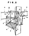
- Figure 2 is a perspective view showing the scaffolding unit of Figure 1 attached to the corner between a pair of horizontal I-section beams disposed at right angles relative to each other;
- Figure 3 is a side elevational view of the scaffolding unit when in the folded configuration;
- Figure 4 is an exploded perspective view of a hinge and a hook member of the scaffolding unit; and
- Figure 5 is a side elevational view, partially in cross-section, of the hinge and hook member of Figure 5.
- The principle of the present invention is particularly useful when embodied in a scaffolding unit such as shown in Figures 1 and 2.
- The scaffolding unit includes four
horizontal base bars 4 connected together into a rectangle so as to surround arectangular bottom portion 5, a pair of relativelyshort front struts 2 each pivotally connected at one end to the respective front corner of therectangular bottom portion 5, and a pair of relatively longrear struts 3 each pivotally connected at one end to the respective rear corner of therectangular bottom portion 5. - The principle of the present invention is particularly useful when embodied in a scaffolding unit such as shown in Figures 1 and 2.
- The scaffolding unit includes four
horizontal base bars 4 connected together into a rectangle so as to surround arectangular bottom portion 5, a pair of relativelyshort front struts 2 each pivotally connected at one end to the respective front corner of therectangular bottom portion 5, and a pair of relatively longrear struts 3 each pivotally connected at one end to the respective rear corner of therectangular bottom portion 5. -
Diagonal tie members 6 and a horizontal rail 7 are pivotally mounted between thefront struts 2 so as to serve respectively as braces and a handrail. Pivotally connected to and extending between each of thefront struts 2 and the correspondingrear struts 3 are a pair ofhorizontal rails - A pair of hangers or
supports 10 are supported between an upper portion of eachrear strut 3 and an upper portion of the correspondingfront strut 2 and each hanger orsupport 10 is foldable each about an intermediate pivot a. As thehangers 10 are expanded or moved into a straight line form, thebottom portion 5 together with thefront struts 2, are moved forwardly to form a gondola-type unit as shown in Figures 1 and 2. To the contrary, as thehangers 10 are folded about the respective pivots a, both thebottom portion 5 and thefront struts 2, are pulled upwardly so that the entire scaffolding unit is folded into a compact size, as shown in Figure 3. - Alternatively, a telescopic rod or chain may be used in place of the foldable support or
hanger 10. - Figures 4 and 5 shown an attaching device and a
hook member 19. An attaching device andhook member 19 is fixedly secured to the upper rear surface or upper side surface of each of therear strut 3, and is connected to eachrear strut 3 via an attachment device. - The attachment device comprises a
hinge 18 composed of a pair ofhinge plate pieces pivot pin 13, eachhinge plate piece holes bolts 35. - The attaching device and
hook member 19 includes aclaw 20, a screw-threadedbolt 21 connected to theclaw 20, atube 22 in engagement with thescrew bolt 21, ahook 24 screw-threadedly mounted on thescrew bolt 21. - The
claw 20 has upper and lower supportingportions portion 27, all formed integrally with the body of theclaw 20. Aspacer 28 is supported between these supportingportions claw 28 by anut 30 andbolt 29. Thespacer 28 has in its central portion a slot 31 (for a purpose described below) and in its rear portion a screw-threadedhole 32 into which thescrew bolt 21 inserted through ahole 33 in theportion 27. Designated at 34 is a stop member which engages thebolt 21 and which prevents angular movement of thespacer 28. - The
hinge plate piece 14 of thehinge 18 is fixedly secured to rear surface 3a of therear strut 3 bybolts 35 andnuts 36. The otherhinge plate piece 15 of thehinge 18 is inserted through theslot 31 in thespacer 28. Thehinge plate piece 15, the body of theclaw 20, and thespacer 28 are joined together as a unit by means of thebolt 29 and thenut 30. - It is important, though one
hinge plate piece 14 of thehinge 18 is not-movably fixed to therear strut 3, that both the otherhinge plate piece 15 and thehook member 19 are pivotally movable in either direction as desired about thepivot pin 13 so that the scaffolding unit can be installed either horizontally at a right angle to an I-section beam or in a horizontal inclined position relative to an I-section beam. - Further, since the
claw 20 is connected to therear strut 3 via thehinge 18 there is no danger that when theclaw 3 is hooked and fastened to an I beam for example, reaction of the fastening force could act on therear strut 3. - For example as shown in Figures 1 and 5 where the scaffolding unit is to be attached to a front surface h1 of the I-section beam H horizontally, the rear surfaces 3a of the two
rear struts 3 are abutted against the front surface h1 of the I-section beam H, then theclaw 20 is hooked on the same front surface h1, and thehook 23 is moved until it reaches a rear surface h2 of the I-section beam H, whereupon thetube 22 is pushed forwardly by rotating thenut 24. As a result, thehook member 19 is connected to the I-section beam H via both theclaw 20 and thehook 23; that is, the scaffolding unit when in the gondola form is installed on the front surface of the I -section beam H so that a workperson may stand on the scaffolding unit for work on or around the I-section beam H. - At that time as the
nut 24 of thehook member 19 is tightened, theclaw 20 is forced against the I-section beam H so as to bite into its front surface h1, but reaction of such force acts only on thehook 23 and does not act on therear struts 3, thus preventing therear struts 3 from being accidentally inclined. - In the example shown in Figure 2 where the scaffolding unit is to be attached to the corner between a pair of perpendicularly intersecting I-section beams H supported on a framework, the scaffolding unit is attached to the I-section beams H by the two
hook members 19 one ater the other in the same manner as in the example described with reference to Figures 1 and 5. - In this example, the
hook members 19 are mounted initially at an inclined position, and each of thehook members 19 is then shifted, by turning one of thehinge plate pieces 15 of ahinge 18 through a desired angle, so as to extend perpendicularly to the respective I-section beam H. Therefore, when thehook members 19 are fastened or tightened, no reaction due to such fastening is exerted on the respectiverear struts 3, thus preventing the scaffolding unit from being damaged during installation. - With the scaffolding unit thus constructed, following advantageous results can be achieved.
- 1) As the
hangers 10 are unfolded, the scaffolding unit can be easily shaped into a gondola form by gravity; and when thehangers 10 are folded, thefront struts 2 together with thebottom portion 5 are moved towards therear struts 3 so as to fold the scaffolding unit into a compact size. - 2) Since it can be folded compactly without separating the individual components, the scaffolding unit is convenient to transport and to keep in storage, thus minimizing the space for storage.
- 3) Since the scaffolding unit can be installed and removed at the working site simply by attaching and detaching the hook members, it is possible to save time and labour in installing and removing the scaffolding unit.
- 4) Since the hook members are attached to the rear struts via the hinge, it is possible to install the scaffolding unit either at a right angle to a support or at a corner.
- 5) Since the hook members are attached to the rear struts via the hinge, no reaction due to fastening of the hook members acts on the rear struts, thus preventing the rear struts from being accidentally inclined or otherwise damaged.
Claims (1)
Priority Applications (2)
| Application Number | Priority Date | Filing Date | Title |
|---|---|---|---|
| DE8888303486T DE3869764D1 (en) | 1988-04-18 | 1988-04-18 | FOLDABLE SCAFFOLDING UNIT. |
| EP88303486A EP0338145B1 (en) | 1988-04-18 | 1988-04-18 | Foldable scaffolding unit |
Applications Claiming Priority (1)
| Application Number | Priority Date | Filing Date | Title |
|---|---|---|---|
| EP88303486A EP0338145B1 (en) | 1988-04-18 | 1988-04-18 | Foldable scaffolding unit |
Publications (2)
| Publication Number | Publication Date |
|---|---|
| EP0338145A1 EP0338145A1 (en) | 1989-10-25 |
| EP0338145B1 true EP0338145B1 (en) | 1992-04-01 |
Family
ID=8200036
Family Applications (1)
| Application Number | Title | Priority Date | Filing Date |
|---|---|---|---|
| EP88303486A Expired - Lifetime EP0338145B1 (en) | 1988-04-18 | 1988-04-18 | Foldable scaffolding unit |
Country Status (2)
| Country | Link |
|---|---|
| EP (1) | EP0338145B1 (en) |
| DE (1) | DE3869764D1 (en) |
Families Citing this family (6)
| Publication number | Priority date | Publication date | Assignee | Title |
|---|---|---|---|---|
| CA2141647A1 (en) * | 1995-02-01 | 1996-08-02 | Keith L. Oakes | Collapsible catwalk |
| JP6851784B2 (en) * | 2016-11-09 | 2021-03-31 | アルインコ株式会社 | Suspended scaffolding |
| CN106958345B (en) * | 2017-05-16 | 2022-08-02 | 简华炽 | Adjustable rigid hanging basket |
| CN108331319A (en) * | 2018-02-07 | 2018-07-27 | 台山市东扩钢构有限公司 | A kind of collapsible steel building platform device for high-altitude operation |
| CN108104452A (en) * | 2018-02-07 | 2018-06-01 | 台山市东扩钢构有限公司 | A kind of new steel structure builds platform device for high-altitude operation |
| CN111056421A (en) * | 2020-01-19 | 2020-04-24 | 广西建工集团建筑工程总承包有限公司 | Hanging basket special for hoisting equipment |
Family Cites Families (5)
| Publication number | Priority date | Publication date | Assignee | Title |
|---|---|---|---|---|
| CH116763A (en) * | 1925-11-23 | 1926-09-16 | Josef Kral | Device for protection when work is carried out outside the window opening. |
| FR732827A (en) * | 1931-03-21 | 1932-09-26 | scaffolding | |
| US2049893A (en) * | 1935-12-03 | 1936-08-04 | Francis L Robertson | Support for scaffolds or the like |
| CH219362A (en) * | 1941-06-19 | 1942-02-15 | Scherrer Bruno | Device for holding scaffolding poles. |
| JPS6146123Y2 (en) * | 1978-12-12 | 1986-12-25 |
-
1988
- 1988-04-18 DE DE8888303486T patent/DE3869764D1/en not_active Expired - Lifetime
- 1988-04-18 EP EP88303486A patent/EP0338145B1/en not_active Expired - Lifetime
Also Published As
| Publication number | Publication date |
|---|---|
| EP0338145A1 (en) | 1989-10-25 |
| DE3869764D1 (en) | 1992-05-07 |
Similar Documents
| Publication | Publication Date | Title |
|---|---|---|
| US4029173A (en) | Foldable scaffold devices | |
| US3082843A (en) | Demountable scaffolding for side mounting on columns | |
| US5127492A (en) | Scaffolding | |
| US6494291B2 (en) | Foldable scaffold device | |
| US6533069B1 (en) | Multi-use ladder support apparatus | |
| CA1268505A (en) | Safety guard rail for scaffolding | |
| US6026932A (en) | Flush mounting scaffolding brace | |
| US3908793A (en) | Adjustable metal scaffold | |
| US4773506A (en) | Scaffolding module and method of erecting same | |
| US3231043A (en) | Scaffolding device | |
| US2593386A (en) | Folding scaffold | |
| EP0338145A1 (en) | Foldable scaffolding unit | |
| US4972924A (en) | Modular scaffolding gantry | |
| US3788424A (en) | Hoist assembly for use on scaffolds | |
| US4189029A (en) | Scaffold device | |
| SK94797A3 (en) | Ladder-supported working platform | |
| US5372218A (en) | Mini portable scaffolding | |
| CN219548350U (en) | Bench instrument is hung to reinforcing bar | |
| JP3538511B2 (en) | Temporary handrail for temporary scaffolding and method of assembling and disassembling temporary scaffolding | |
| JPH0311298Y2 (en) | ||
| JPH0913656A (en) | Built-up scaffolding | |
| CN214462389U (en) | A kind of scaffolding for construction engineering | |
| CN219081073U (en) | Assembled externally hung protection system | |
| JPH0321569Y2 (en) | ||
| JPH0525986B2 (en) |
Legal Events
| Date | Code | Title | Description |
|---|---|---|---|
| PUAI | Public reference made under article 153(3) epc to a published international application that has entered the european phase |
Free format text: ORIGINAL CODE: 0009012 |
|
| AK | Designated contracting states |
Kind code of ref document: A1 Designated state(s): DE FR GB IT NL |
|
| 17P | Request for examination filed |
Effective date: 19900228 |
|
| 17Q | First examination report despatched |
Effective date: 19901029 |
|
| GRAA | (expected) grant |
Free format text: ORIGINAL CODE: 0009210 |
|
| AK | Designated contracting states |
Kind code of ref document: B1 Designated state(s): DE FR GB IT NL |
|
| REF | Corresponds to: |
Ref document number: 3869764 Country of ref document: DE Date of ref document: 19920507 |
|
| ET | Fr: translation filed | ||
| ITF | It: translation for a ep patent filed | ||
| PLBE | No opposition filed within time limit |
Free format text: ORIGINAL CODE: 0009261 |
|
| STAA | Information on the status of an ep patent application or granted ep patent |
Free format text: STATUS: NO OPPOSITION FILED WITHIN TIME LIMIT |
|
| 26N | No opposition filed | ||
| PGFP | Annual fee paid to national office [announced via postgrant information from national office to epo] |
Ref country code: FR Payment date: 19970407 Year of fee payment: 10 |
|
| PGFP | Annual fee paid to national office [announced via postgrant information from national office to epo] |
Ref country code: NL Payment date: 19970430 Year of fee payment: 10 |
|
| PGFP | Annual fee paid to national office [announced via postgrant information from national office to epo] |
Ref country code: DE Payment date: 19970522 Year of fee payment: 10 |
|
| PG25 | Lapsed in a contracting state [announced via postgrant information from national office to epo] |
Ref country code: FR Free format text: THE PATENT HAS BEEN ANNULLED BY A DECISION OF A NATIONAL AUTHORITY Effective date: 19980430 |
|
| PGFP | Annual fee paid to national office [announced via postgrant information from national office to epo] |
Ref country code: GB Payment date: 19980515 Year of fee payment: 11 |
|
| PG25 | Lapsed in a contracting state [announced via postgrant information from national office to epo] |
Ref country code: NL Free format text: LAPSE BECAUSE OF NON-PAYMENT OF DUE FEES Effective date: 19981101 |
|
| NLV4 | Nl: lapsed or anulled due to non-payment of the annual fee |
Effective date: 19981101 |
|
| PG25 | Lapsed in a contracting state [announced via postgrant information from national office to epo] |
Ref country code: DE Free format text: LAPSE BECAUSE OF NON-PAYMENT OF DUE FEES Effective date: 19990202 |
|
| REG | Reference to a national code |
Ref country code: FR Ref legal event code: ST |
|
| PG25 | Lapsed in a contracting state [announced via postgrant information from national office to epo] |
Ref country code: GB Free format text: LAPSE BECAUSE OF NON-PAYMENT OF DUE FEES Effective date: 19990418 |
|
| GBPC | Gb: european patent ceased through non-payment of renewal fee |
Effective date: 19990418 |
|
| PG25 | Lapsed in a contracting state [announced via postgrant information from national office to epo] |
Ref country code: IT Free format text: LAPSE BECAUSE OF NON-PAYMENT OF DUE FEES Effective date: 20050418 |