EP0337620B1 - Dispositif pour faire varier la durée d'échapement - Google Patents
Dispositif pour faire varier la durée d'échapement Download PDFInfo
- Publication number
- EP0337620B1 EP0337620B1 EP89302863A EP89302863A EP0337620B1 EP 0337620 B1 EP0337620 B1 EP 0337620B1 EP 89302863 A EP89302863 A EP 89302863A EP 89302863 A EP89302863 A EP 89302863A EP 0337620 B1 EP0337620 B1 EP 0337620B1
- Authority
- EP
- European Patent Office
- Prior art keywords
- exhaust timing
- exhaust
- valve
- ignition switch
- alarm lamp
- Prior art date
- Legal status (The legal status is an assumption and is not a legal conclusion. Google has not performed a legal analysis and makes no representation as to the accuracy of the status listed.)
- Expired - Lifetime
Links
Images

Classifications
-
- F—MECHANICAL ENGINEERING; LIGHTING; HEATING; WEAPONS; BLASTING
- F02—COMBUSTION ENGINES; HOT-GAS OR COMBUSTION-PRODUCT ENGINE PLANTS
- F02D—CONTROLLING COMBUSTION ENGINES
- F02D13/00—Controlling the engine output power by varying inlet or exhaust valve operating characteristics, e.g. timing
- F02D13/02—Controlling the engine output power by varying inlet or exhaust valve operating characteristics, e.g. timing during engine operation
- F02D13/028—Controlling the engine output power by varying inlet or exhaust valve operating characteristics, e.g. timing during engine operation for two-stroke engines
- F02D13/0284—Variable control of exhaust valves only
-
- F—MECHANICAL ENGINEERING; LIGHTING; HEATING; WEAPONS; BLASTING
- F01—MACHINES OR ENGINES IN GENERAL; ENGINE PLANTS IN GENERAL; STEAM ENGINES
- F01M—LUBRICATING OF MACHINES OR ENGINES IN GENERAL; LUBRICATING INTERNAL COMBUSTION ENGINES; CRANKCASE VENTILATING
- F01M11/00—Component parts, details or accessories, not provided for in, or of interest apart from, groups F01M1/00 - F01M9/00
- F01M11/10—Indicating devices; Other safety devices
-
- F—MECHANICAL ENGINEERING; LIGHTING; HEATING; WEAPONS; BLASTING
- F02—COMBUSTION ENGINES; HOT-GAS OR COMBUSTION-PRODUCT ENGINE PLANTS
- F02B—INTERNAL-COMBUSTION PISTON ENGINES; COMBUSTION ENGINES IN GENERAL
- F02B77/00—Component parts, details or accessories, not otherwise provided for
- F02B77/04—Cleaning of, preventing corrosion or erosion in, or preventing unwanted deposits in, combustion engines
-
- F—MECHANICAL ENGINEERING; LIGHTING; HEATING; WEAPONS; BLASTING
- F02—COMBUSTION ENGINES; HOT-GAS OR COMBUSTION-PRODUCT ENGINE PLANTS
- F02B—INTERNAL-COMBUSTION PISTON ENGINES; COMBUSTION ENGINES IN GENERAL
- F02B77/00—Component parts, details or accessories, not otherwise provided for
- F02B77/08—Safety, indicating or supervising devices
- F02B77/083—Safety, indicating or supervising devices relating to maintenance, e.g. diagnostic device
-
- F—MECHANICAL ENGINEERING; LIGHTING; HEATING; WEAPONS; BLASTING
- F02—COMBUSTION ENGINES; HOT-GAS OR COMBUSTION-PRODUCT ENGINE PLANTS
- F02B—INTERNAL-COMBUSTION PISTON ENGINES; COMBUSTION ENGINES IN GENERAL
- F02B75/00—Other engines
- F02B75/02—Engines characterised by their cycles, e.g. six-stroke
- F02B2075/022—Engines characterised by their cycles, e.g. six-stroke having less than six strokes per cycle
- F02B2075/025—Engines characterised by their cycles, e.g. six-stroke having less than six strokes per cycle two
-
- Y—GENERAL TAGGING OF NEW TECHNOLOGICAL DEVELOPMENTS; GENERAL TAGGING OF CROSS-SECTIONAL TECHNOLOGIES SPANNING OVER SEVERAL SECTIONS OF THE IPC; TECHNICAL SUBJECTS COVERED BY FORMER USPC CROSS-REFERENCE ART COLLECTIONS [XRACs] AND DIGESTS
- Y02—TECHNOLOGIES OR APPLICATIONS FOR MITIGATION OR ADAPTATION AGAINST CLIMATE CHANGE
- Y02T—CLIMATE CHANGE MITIGATION TECHNOLOGIES RELATED TO TRANSPORTATION
- Y02T10/00—Road transport of goods or passengers
- Y02T10/10—Internal combustion engine [ICE] based vehicles
- Y02T10/12—Improving ICE efficiencies
Definitions
- This invention relates to a system for changing exhaust timing of a two-cycle engine particularly adapted to effectively perform a self-cleaning operation of an exhaust timing valve at the starting time of an engine operation (EP-A-246093).
- an exhaust timing controlling device of a two-stroke cycle engine in which a recessed portion is formed to the upper surface near an exhaust port provided for an exhaust passage and opened to an inner peripheral surface of a cylinder of the engine.
- a valve member is accommodated in the recessed portion so as to project or retract therefrom, and the exhaust timing is changed by changing the height of the exhaust port by displacing the valve member from the retracting position to the projecting position.
- Such controlling is performed by an electric controller.
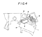
- a two-cycle engine of conventional type is also shown in Fig.4.
- the two-cycle engine is provided with an exhaust timing valve 2 disposed for an exhaust passage 1 for taking the exhaust timing of the engine.
- the exhaust timing valve 2 is disposed so as to be movable forwardly and backwardly with respect to an exhaust port 4 with the timing in accordance with the revolution numbers of the engine by the actuation of an actuating mechanism 3 operatively coupled with a crank member.
- the exhaust timing valve 2 is forwardly moved towards the exhaust port 4 when the engine is rotated at a low or neutral speed to delay the exhaust timing and the exhaust timing valve 2 is on the contrary backwardly moved when the engine is rotated at a high speed to speed up the exhaust timing.
- the exhaust timing valve 2 of the character described above is moved along a valve guide member 5 which is secured to a cylinder block 6 by means of a bolt.
- a timer circuit is arranged in a motor driving circuit of an actuator controller for driving and controlling the exhaust timing valve 2, and the timer circuit actuates the motor driving circuit means for about 1 to 2 seconds from the time immediately after the "ON" switching operation of an ignition switch to the starting of the engine operation.
- a motor is thus operated as an actuator for the exhaust timing valve to move forwardly or backwardly the exhaust timing valve 2 to thereby remove the carbon or the like sticked on the sliding surface of the exhaust timing valve 2.
- An object of this invention is to eliminate the defects encountered to the conventional technique described above and to provide a system for changing exhaust timing of an engine provided with an improved function for performing a self-cleaning operation of an exhaust timing valve with a simple structure of a control unit.
- the actuator controller is operated to displace the exhaust timing valve forwardly or backwardly to thereby carry out the self-cleaning operation thereof.
- the actuator controller is operatively connected to the oil alarm lamp checking circuit, so that the exhaust timing valve carries out the self-cleaning operation during the operation of the checking circuit.
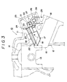
- a two-cycle engine generally designated by reference numeral 10 includes a cylinder block 11 into which a cylinder 12 is mounted.
- a piston member 13 is slidably mounted in the cylinder 12.
- the side wall of the cylinder 12 is provided with a scavenge port, not shown, for introducing fresh air into a combustion chamber 14 and an exhaust port 15 for exhausting combustion gas burned in a combustion chamber 14, these ports being opened to the inner hollow portion of the cylinder 12.
- An exhaust passage 16 extends inwardly from the exhaust port 15.
- Two sets of exhaust timing valves 17 and valve guides 18 are arranged to the cylinder block 11 above and in the vicinity of the upper portion of the exhaust port 15.
- Each of the exhaust timing valve 17 comprises operating member 19 slidably engaged with a guiding portion of the valve guide 18, a rod member 20 fitted in the inner portion of the valve guide 18 through an insertion end 23 thereof, and a stopping member 21 fitted and secured to the rod member 20.
- the valve guide 18 is secured to the cylinder block 11 by means of a fastening screw 24. According to, this construction, the exhaust timing valve 17 is guided forwardly or backwardly with respect to the exhaust port 15.
- An operation chamber 25 is defined in the cylinder block 11, and within the operation chamber 25 are located the rod member 20 and the stopping member 21 of the exhaust timing valve 17, and an actuating mechanism 26, described hereinlater.
- the actuating mechanism 26 comprises an actuating arm 27, a follower pulley 28 and a driving cable 29 which is stretched around the follower pulley 28 and a driving pulley, not shown, operatively coupled with an electric motor 31 in Fig. 1 as an actuator for the exhaust timing valve 17.
- the motor 31 is a reversible motor such as a stepping motor or survo-motor driven in accordance with the revolution numbers of the engine.
- the actuating arm 27 is coupled with the follower pulley 28 through a shaft member, not shown, and operatively engaged with a pin 30 secured to the stopping member 21 of the exhaust timing valve 17.
- the follower pulley 28 is positively rotated by the positive rotation of the motor 31 through the driving cable 29 to thereby rotate the actuating arm 27 in an arrowed direction and retract the exhaust timing valve 17 from the exhaust port 15 to a position in which the front surface of the valve 17 is overlapped with a surface of a discharge passage 16 shown by two-dot and dash lines A.
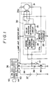
- the operation of the motor 31 is controlled by an actuator controller 32, which compsises, as shown in Fig. 1, a circuit 33 for driving the motor 31, a circuit 34 for detecting the revolution numbers of the engine and a circuit 35 for detecting the position of the valve.
- the motor driving circuit 33 serves to calculate an rotation angle of the engine in accordance with the revolution numbers of the engine in response to a signal detected by the engine revolution number detecting circuit 34 to thereby rotate the motor 31 by the rotation amounts in accordance with the detected revolution numbers of the engine.
- the rotation angle of the motor 31 is detected by the valve position detecting circuit 35 including a potentiometer 35a and a detected signal is transmitted into the motor driving circuit 33. Accordingly, the motor driving circuit 33 serves to drive positively or reversely the motor 31 in response to the position signal from the valve position detecting circuit 35 to thereby regulate or correct the displacement of the exhaust timing valve 17.
- the actuator controller 32 generally comprising the motor driving circuit 33, the engine revolution number detecting circuit 34 and the valve position detecting circuit 35 is operatively connected to a battery 37 through an ignition switch 36.
- the motor driving circuit 33 is also connected to a circuit 38 for checking an oil alarm lamp through a wiring 33a.
- the oil alarm lamp checking circuit 38 serves to flow an electric current from the battery 37 to a diode 39 and an oil alarm lamp 40 by the switching of the position of the ignition switch 36 before the starting of the engine operation to check a fact as to whether or not the oil alarm lamp is lightened.
- the circuit 38 includes an oil level switch 41 for detecting the level of the engine oil.
- the ignition switch 36 is provided with four contact points A, B, C, and D.
- the contact point A is connected to the oil alarm lamp checking circuit 38
- the contact point B is connected to the oil level switch 41
- the contact point C is connected to a lamp unit and an ignition unit
- the contact point D is connected to the battery 37.
- the ignition switch 36 is further provided with an ON position 42, an OFF position 43 and a CHECK position 44 which is disposed at a neutral position in the rotating direction of the ignition switch 36 between the ON position 42 and the OFF position 43.
- the contact point D is not connected either to the contact points A, B and C in the OFF position 43 of the ignition switch 36.
- the contact point D is connected to the contact points A and B in the CHECK position 44 to enable, i.e. "ON” state the power sources of the actuator controller 32 and the oil alarm lamp checking circuit 38 as shown in Fig. 2.
- the contact point D is further connected to the contact points B and C in the ON position 42 to make “ON” state the power sources of the lamp unit and the lightening unit to maintain the "ON" state of the actuator controller 32.
- the motor driving circuit 33 is connected to the oil alarm lamp checking circuit 38 through the wiring 33a for the signal transmission. Therfore, when the ignition switch 36 is set to the CHECK position 44 and the oil alarm lamp checking circuit 38 is operated, a signal representing the starting of the self-cleaning operation is transmitted into the motor driving circuit 33, which then serves to drive the motor 31 in the positive direction as shown in Fig. 2 and to forwardly move the exhaust timing valve 17 towards the exhaust port 15.
- the motor driving circuit 33 also serves to retract the exhaust timing valve 17 from the exhaust port 15 at the disapperance of the self-cleaning operation starting signal.
- the ignition switch 36 is first rotated from the OFF position 43 to the ON position 42 to start the engine. On the way of this rotation, the rotation of the ignition switch 36 is temporarily stopped at the CHECK position 44 to check or inspect the lightening of the oil alarm lamp 40 by passing the electric current through the check circuit 38.
- the signal for starting the operation of the self-cleaning of the valve 17 is transmitted to the motor driving circuit 33 through the wiring 33a during the inspection of the oil alarm lamp and the motor 31 is driven in the positive direction to forwardly move the exhaust timing valve 17 towards the exhaust port 15.
- the ignition switch 36 Upon the completion of the checking of the oil alarm lamp 40, the ignition switch 36 is rotated to set the same to the ON position 42. In advance of the setting to the ON position 42, the connection between the contact D and the contact A is released to thereby interrupt the currenting to the oil alarm lamp checking circuit 38. In response to this interruption, the transmission of the self-cleaning signal to the motor driving circuit 33 from the wiring 33a stops, and the motor 31 is then rotated reversely to retract the exhaust timing valve 17 from the exhaust port 15, whereby the self-cleaning operation for the exhaust timing valve 17 can be performed before the starting of the engine driving to thereby remove the carbon, for example, stuck on the surface of the valve 17.
- the ignition switch 36 When the ignition switch 36 is set to the ON position 42, the electric current passes the lamp unit and the ignition unit to thereby start the engine.
- the ignition switch 36 is provided with the CHECK position 44 in addition to the ON and OFF positions 42 and 43.
- the oil alarm lamp checking circuit 38 is currented only at the time when the ignition switch 36 is set to the CHECK position 44, and only during this current conducting period, the self-cleaning signal is transmitted to the motor driving circuit 33, so that there is no need for the actuator controller 32 to locate any specific or leased timer for controlling the self-cleaning of the exhaust timing valve 17. This significantly makes compact the actuator controller and reduces the cost involved for locating the leased timer.
Claims (3)
- Système pour modifier la durée d'échappement d'un moteur à deux temps du type comprenant une vanne de durée d'échappement disposée près d'un orifice d'échappement du moteur pour être déplaçable vers l'avant ou vers l'arrière par rapport à l'orifice d'échappement (15), un mécanisme pour faire fonctionner la vanne de durée d'échappement (17), une unité de commande (32) reliée de manière opérationnelle au mécanisme de fonctionnement pour commander le fonctionnement de la vanne de durée d'échappement, une unité de commutateur d'allumage reliée de manière opérationnelle à l'unité de commande, une unité de vérification de voyant d'alarme d'huile reliée de manière opérationnelle à l'unité de commutateur d'allumage pour vérifier l'éclairage d'un voyant d'alarme d'huile, et une source de courant reliée de manière opérationnelle à l'unité de commutateur d'allumage et à l'unité de vérification de voyant d'alarme d'huile, ledit système pour modifier la durée d'échappement étant caractérisé en ce que ladite unité de commutateur d'allumage (36) est pourvue d'une position ON (42) et d'une position OFF (43) et d'une position CHECK (44), ladite position CHECK (44) étant reliée de manière opérationnelle audit circuit (38) de vérification de voyant d'alarme d'huile seulement au moment où ladite unité de commutateur d'allumage (36) prend ladite position CHECK (44), et ladite unité (38) de vérification de voyant d'alarme d'huile est reliée de manière opérationnelle à ladite unité de commande (32) de façon à ce que ladite unité de commande (32) actionne ledit mécanisme de fonctionnement (26) pour déplacer ladite vanne de durée d'échappement (17) par rapport audit orifice d'échappement (15) quand l'unité de commutateur d'allumage (36) est sur la position CHECK (44), ce par quoi une opération d'autonettoyage pour ladite vanne de durée d'échappement (17) est menée à bonne fin.
- Système pour modifier la durée d'échappement selon la revendication 1, dans lequel ladite position CHECK (44) est située entre lesdites positions ON et OFF (42) et (43).
- Système pour modifier la durée d'échappement selon la revendication 1, dans lequel ladite unité de commande (32) comprend un circuit (34) de détection de nombre de tours de moteur à deux temps, un circuit (35) de détection de position de vanne et un circuit (33) de pilotage de moteur qui est relié de manière opérationnelle à ladite unité de vérification de voyant d'alarme d'huile (38) au moyen d'un câblage (33a).
Applications Claiming Priority (2)
| Application Number | Priority Date | Filing Date | Title |
|---|---|---|---|
| JP6976988A JP2595487B2 (ja) | 1988-03-25 | 1988-03-25 | 排気タイミング可変装置 |
| JP69769/88 | 1988-03-25 |
Publications (2)
| Publication Number | Publication Date |
|---|---|
| EP0337620A1 EP0337620A1 (fr) | 1989-10-18 |
| EP0337620B1 true EP0337620B1 (fr) | 1993-08-25 |
Family
ID=13412334
Family Applications (1)
| Application Number | Title | Priority Date | Filing Date |
|---|---|---|---|
| EP89302863A Expired - Lifetime EP0337620B1 (fr) | 1988-03-25 | 1989-03-22 | Dispositif pour faire varier la durée d'échapement |
Country Status (3)
| Country | Link |
|---|---|
| EP (1) | EP0337620B1 (fr) |
| JP (1) | JP2595487B2 (fr) |
| DE (1) | DE68908591T2 (fr) |
Families Citing this family (1)
| Publication number | Priority date | Publication date | Assignee | Title |
|---|---|---|---|---|
| CN109578108B (zh) * | 2018-12-26 | 2020-04-03 | 东风汽车集团有限公司 | 一种用于曲轴箱通气管的诊断加热装置、通气管、通风系统和汽车 |
Family Cites Families (5)
| Publication number | Priority date | Publication date | Assignee | Title |
|---|---|---|---|---|
| JPS5692314A (en) * | 1979-12-27 | 1981-07-27 | Yamaha Motor Co Ltd | Exhaust timing controlling apparatus for two-cycle engine |
| JPS5762917A (en) * | 1980-09-30 | 1982-04-16 | Yamaha Motor Co Ltd | Exhaust timing control device for 2-cycle engine |
| JPS5776226A (en) * | 1980-10-30 | 1982-05-13 | Yamaha Motor Co Ltd | Device for preventing sticking of exhaust valve |
| US4539547A (en) * | 1983-04-25 | 1985-09-03 | Ford Motor Company | Low liquid level sensing and warning circuit |
| JPS62267515A (ja) * | 1986-05-14 | 1987-11-20 | Honda Motor Co Ltd | 2サイクルエンジンの排気時期制御装置 |
-
1988
- 1988-03-25 JP JP6976988A patent/JP2595487B2/ja not_active Expired - Lifetime
-
1989
- 1989-03-22 DE DE89302863T patent/DE68908591T2/de not_active Expired - Fee Related
- 1989-03-22 EP EP89302863A patent/EP0337620B1/fr not_active Expired - Lifetime
Also Published As
| Publication number | Publication date |
|---|---|
| JPH01244112A (ja) | 1989-09-28 |
| DE68908591D1 (de) | 1993-09-30 |
| EP0337620A1 (fr) | 1989-10-18 |
| JP2595487B2 (ja) | 1997-04-02 |
| DE68908591T2 (de) | 1993-12-23 |
Similar Documents
| Publication | Publication Date | Title |
|---|---|---|
| US4976636A (en) | Trim apparatus for marine propulsion unit | |
| US4371051A (en) | Automatic switching-off arrangement | |
| KR900003945B1 (ko) | 스로틀밸브 제어장치 | |
| EP0337620B1 (fr) | Dispositif pour faire varier la durée d'échapement | |
| JPS6315468B2 (fr) | ||
| US5285757A (en) | Arrangement for controlling an actuable element in a motor vehicle having a drive unit | |
| JPS6334307B2 (fr) | ||
| US20030154015A1 (en) | Engine speed control system | |
| EP1593830B1 (fr) | Dispositif de commande de moteur pour engin de chantier | |
| US5700168A (en) | Electronic ignition interruption apparatus | |
| JPH0639057Y2 (ja) | 2サイクルエンジンの排気制御装置 | |
| EP0663519B1 (fr) | Dispositif pour commander un moteur à combustion | |
| CA1211657A (fr) | Mecanisme de gouverne pour moteur hors-bord electrique | |
| KR200178185Y1 (ko) | 수동 변속차량의 중립 상태시 엔진 회전수 조절장치 | |
| KR100235719B1 (ko) | 엔진의 타이밍 세팅기구 | |
| KR100435945B1 (ko) | 공회전시의 과회전(over revolution)방지장치 및그에 따른 제어방법 | |
| KR200144583Y1 (ko) | 소각로의 버너 게이트 장치 | |
| JP2595486B2 (ja) | 排気タイミング可変装置 | |
| KR100254969B1 (ko) | 자동차의 스로틀밸브 개방각 제어장치 | |
| AU2001279491B2 (en) | Engine speed control system | |
| JP2521877B2 (ja) | エンジンの絞り弁操作装置 | |
| CN2370168Y (zh) | 机动车强制怠速自动节能减污的装置 | |
| KR950001570Y1 (ko) | 자동크러치용 엑세레이터 감지장치 | |
| KR100285439B1 (ko) | 자동차의 변속장치 | |
| SE8704316D0 (sv) | Marin drivanordning med servoassisterad styrning, vexling och gasreglering |
Legal Events
| Date | Code | Title | Description |
|---|---|---|---|
| PUAI | Public reference made under article 153(3) epc to a published international application that has entered the european phase |
Free format text: ORIGINAL CODE: 0009012 |
|
| 17P | Request for examination filed |
Effective date: 19890407 |
|
| AK | Designated contracting states |
Kind code of ref document: A1 Designated state(s): DE FR GB |
|
| 17Q | First examination report despatched |
Effective date: 19910517 |
|
| GRAA | (expected) grant |
Free format text: ORIGINAL CODE: 0009210 |
|
| RAP1 | Party data changed (applicant data changed or rights of an application transferred) |
Owner name: SUZUKI KABUSHIKI KAISHA |
|
| AK | Designated contracting states |
Kind code of ref document: B1 Designated state(s): DE FR GB |
|
| REF | Corresponds to: |
Ref document number: 68908591 Country of ref document: DE Date of ref document: 19930930 |
|
| ET | Fr: translation filed | ||
| PLBE | No opposition filed within time limit |
Free format text: ORIGINAL CODE: 0009261 |
|
| STAA | Information on the status of an ep patent application or granted ep patent |
Free format text: STATUS: NO OPPOSITION FILED WITHIN TIME LIMIT |
|
| 26N | No opposition filed | ||
| PGFP | Annual fee paid to national office [announced via postgrant information from national office to epo] |
Ref country code: GB Payment date: 19970313 Year of fee payment: 9 Ref country code: FR Payment date: 19970313 Year of fee payment: 9 |
|
| PGFP | Annual fee paid to national office [announced via postgrant information from national office to epo] |
Ref country code: DE Payment date: 19970401 Year of fee payment: 9 |
|
| PG25 | Lapsed in a contracting state [announced via postgrant information from national office to epo] |
Ref country code: GB Free format text: LAPSE BECAUSE OF NON-PAYMENT OF DUE FEES Effective date: 19980322 |
|
| PG25 | Lapsed in a contracting state [announced via postgrant information from national office to epo] |
Ref country code: FR Free format text: THE PATENT HAS BEEN ANNULLED BY A DECISION OF A NATIONAL AUTHORITY Effective date: 19980331 |
|
| GBPC | Gb: european patent ceased through non-payment of renewal fee |
Effective date: 19980322 |
|
| PG25 | Lapsed in a contracting state [announced via postgrant information from national office to epo] |
Ref country code: DE Free format text: LAPSE BECAUSE OF NON-PAYMENT OF DUE FEES Effective date: 19981201 |
|
| REG | Reference to a national code |
Ref country code: FR Ref legal event code: ST |