EP0337364A2 - Breakaway exterior mirror for vehicles - Google Patents
Breakaway exterior mirror for vehicles Download PDFInfo
- Publication number
- EP0337364A2 EP0337364A2 EP89106344A EP89106344A EP0337364A2 EP 0337364 A2 EP0337364 A2 EP 0337364A2 EP 89106344 A EP89106344 A EP 89106344A EP 89106344 A EP89106344 A EP 89106344A EP 0337364 A2 EP0337364 A2 EP 0337364A2
- Authority
- EP
- European Patent Office
- Prior art keywords
- mirror
- mirror housing
- cap
- rocker
- housing
- Prior art date
- Legal status (The legal status is an assumption and is not a legal conclusion. Google has not performed a legal analysis and makes no representation as to the accuracy of the status listed.)
- Granted
Links
Images


Classifications
-
- B—PERFORMING OPERATIONS; TRANSPORTING
- B60—VEHICLES IN GENERAL
- B60R—VEHICLES, VEHICLE FITTINGS, OR VEHICLE PARTS, NOT OTHERWISE PROVIDED FOR
- B60R1/00—Optical viewing arrangements; Real-time viewing arrangements for drivers or passengers using optical image capturing systems, e.g. cameras or video systems specially adapted for use in or on vehicles
- B60R1/02—Rear-view mirror arrangements
- B60R1/06—Rear-view mirror arrangements mounted on vehicle exterior
- B60R1/076—Rear-view mirror arrangements mounted on vehicle exterior yieldable to excessive external force and provided with an indexed use position
Definitions
- the invention relates to an exterior mirror for vehicles with a mirror base that can be attached to the body of the vehicle and a mirror housing that is held in the position of use on the mirror base with spring force, wherein an edge of the mirror housing rests on a shoulder of the mirror base and the mirror housing around its rear edge section in the direction of travel against the spring force is pivotable backwards relative to the mirror base.
- the driver must push the swivel arm backwards out of the locking position. This can result in a safety risk for the driver insofar as his fingers can be pinched between the front edge of the mirror housing and the mirror base when the mirror housing is folded back into the position of use under the effect of a tension spring which is usually designed to be strong.
- a releasable locking device between the mirror housing and the mirror base is provided to reduce this safety risk, which on the one hand holds the mirror housing in the pivoted end position and defines it on the other hand, can be solved by a slight impact on the outer edge of the mirror housing, so that the driver is no longer forced to intervene with his hands in the opening between the folded mirror housing and the mirror base.
- the opening between the front edge of the mirror housing and the mirror base remains freely accessible when the mirror housing is folded back.
- the locking mechanism intervenes in the opening by trusting that the mirror housing is securely held in the swivel end position.
- foreign particles or water from washing systems are introduced into the area between the mirror base and the mirror housing after the mirror housing has been folded onto the vehicle body.
- the invention is therefore based on the object to provide a cover for the opening between the mirror housing and the mirror base in an outside mirror, which can be advantageously made of the same material as the mirror housing, therefore is resistant to aging and largely precludes manual access to the opening.
- an edge of the mirror housing resting on a shoulder of the mirror base and the mirror housing around its rear edge section in the direction of travel against the spring force relative to Mirror base is pivotable to the rear, is provided according to the invention to solve the problem that a curved, in the use position enclosed by the mirror housing cap is attached, the curvature of which is centered on the rear edge portion and against the outer contour of the mirror housing at its front edge portion when pivoting is present.
- the cap remains free from the weather when the mirror housing is in use and also does not appear aesthetically.
- the cap can be made from a simple molded plastic part. Finally, it enables the opening between the mirror housing and mirror base to be fully covered when the former is pivoted away.
- the mirror housing can also be swiveled forward relative to the mirror base in a conventional manner, it is advisable in a further development of the invention to link the cap near a front shoulder section on the mirror base and either press it against the mirror housing by means of a spring or to provide a foot on the cap with which it is supported on the mirror base when swiveling backwards.
- link the cap near a front shoulder section on the mirror base and either press it against the mirror housing by means of a spring or to provide a foot on the cap with which it is supported on the mirror base when swiveling backwards.
- a locking member can be formed on the cap, which detachably grips the mirror housing in a rear pivoting end position with respect to the direction of travel.
- This blocking organ can be integrated into the cap shape in that a nose protruding from the outer contour of the cap is provided, which underlies the front edge section in the pivot end position. From the defined swivel end position, the mirror housing can then be freed from the driver's seat by a light impact on the outer parts of the mirror housing, whereupon the mirror housing is automatically pivoted back into its position of use by the tension spring.
- the locking member can be a paragraph of the mirror housing locking bolt, which is fastened within the cap and protrudes little from an opening of the cap, whereby to facilitate the pivoting movement of the mirror housing backwards the bolt can dodge backwards against spring pressure.
- the locking member is in the form of a rocker, which is held by a spring in one of two tilt positions.
- a catch formed on the rocker or the mirror housing falls into a trap and in this way holds the pivoted mirror housing in the pivot end position.
- the mirror housing is pivoted a short distance further to the vehicle body, whereby the rocker is transferred to its second tilt position, in which the catch is released from the trap, so that the mirror housing can be returned to its position of use by the tension spring.
- the mirror housing changes the rocker in its first tilt position, so that it is prepared for locking the mirror housing in its rear swiveling end position.
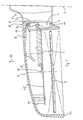
- FIG. 1 first shows an exterior mirror of a known type.
- a mirror base 2 is fastened to a vehicle body 1, shown schematically in dashed lines, in a manner not shown.
- the mirror base 2 On the side facing away from the vehicle body 1, the mirror base 2 has one Mounting plate 4, which, offset from the vehicle body 1, is surrounded by a shoulder 3 which extends around the mounting plate 4 and projects outwards.
- a mirror housing 5 has an edge 18 which is spherically shaped at the end near the mirror base, of which the front edge section 6 and the rear edge section 8 can be seen in FIG. 1.
- the designations "front” and “rear” refer to the direction of travel of the vehicle indicated by arrow 10.
- the edge sections 6, 8 encompass the mounting plate 4 and stand in the position of use of the mirror housing 5 shown in FIG. 1 on corresponding parts of the shoulder 3.
- a strong tension spring 7 is fastened, the end of which is located in the mirror housing 5 is suspended in an eyelet 11 of a support plate 15.
- the support plate 15 is fastened to the front wall 13 of the mirror housing 5 via supports, of which a support 14 remote from the mirror base is indicated in FIG. 1.
- a mirror glass 9 is held on the support plate 15 in a customary manner by means of actuators from the vehicle interior, not shown, which extend through the mirror base 2 and an opening 16 in the mirror housing 5.
- an arm extending into the interior of the mirror housing 5 is articulated on the mounting plate 4 and is held against the inside of the wall 13 by a spring 17.
- a cap designated as a whole by 20 is within the edge 18 in a region of the mounting plate 4 of the mirror base 2 articulated, which is adjacent to the front edge portion 6.
- the mounting plate 4 has a cutout 41, into which a lower end 21 of the cap 20 protrudes and is pivotably held there on a pin 42 about an axis which is perpendicular to the plane of FIG. 2 and is therefore essentially vertical with the exterior mirror mounted on the vehicle is.
- the cap 20, which is a one-piece component and is made of the same plastic as the mirror housing 5, has a curved or curved shape, the curvature of which is centered on the rear edge section 8.
- the shell shape of the cap 20 depends in particular on the outer shape of the edge 18 in such a way that the outer contour 22 of the cap 20 is defined by the shape of the path through which the front edge portion 6 travels when the mirror housing 5 is pivoted backwards.
- An inner thickening 23 is formed on the cap 20 and has a pocket 24 for receiving and holding a compression spring 25.
- the compression spring 25 projects with its free end out of the pocket 24 and can be supported on the top of the mounting plate 4 of the mirror base 2.
- a nose 26 projects outwards, the function of which will be explained below.
- an armature 43 with an eye 44 protrudes toward the mirror housing 5 from the mounting plate 4 approximately in the center.
- the end 19 of the tension spring 7 near the mirror base is suspended in the eye 44.
- a pin-shaped extension 81 is formed on the rear edge section 8, which extends into a rear cutout 45 in the rear side flank of the mounting plate 4.
- the assembly comprising the cap 20 and the compression spring 25 is entirely from the edge 18 of the mirror housing 5 and therefore not visible from the outside.
- the front edge section 6 slides along a first part 27 of the outer contour 22, which is opposite the surrounding one Part 28 of the outer contour projects like a rib with increasing thickness and ends in the nose 26. While the front edge section 6 is sliding along, the cap 20 is pressed around the pin 42 in the direction of the mounting plate 4 against the action of the compression spring 25 which is then supported thereon.
- the cap 20 jumps forward so far that the upper part 29 of its outer contour 22 now lies against the edge 18 from the inside.
- the penetration of the extension 81 through the cutout 45 into the mirror base 2 secures the mirror housing 5 against a displacement relative to the mirror base 2 downwards or upwards.
- the mirror housing 5 can now only return in the direction of its position of use under the action of the tension spring 7 up to its rear pivot end position shown in FIG. 3, which is determined by gripping the front edge section 6 through the nose 26.
- the mirror housing can be released by a short blow or pressure by hand on its outer part 51, as a result of which the front edge section 6 is lifted outward beyond the nose 26, which is made possible by a corresponding size of the rear cutout 45. Thereafter, the mirror housing 5 can automatically return to the position of use shown in FIG. 2 under the action of the tension spring 7.
- the shape of the cap is largely closed by the cap 20.
- the lateral expansion of the cap 20 is not subject to any restrictions, so that it can be chosen so large that the said opening remains practically completely closed from the outside up to the rear swivel end position.
- the rear edge section 8 with extension 81 lifts off the rear part of the shoulder 3, while the front edge section 6 rolls on the front part of the shoulder 3.
- the cap 20 is pivoted forward by the tension spring 7 during this forward pivoting movement, but otherwise does not interfere with the inevitable movements of the tension spring and the other adjusting elements for the mirror 9.
- FIGS. 5 and 6 differs from the first embodiment described above in that, instead of the nose protruding from the outer contour 22 of the cap 20, a separate latch 30 is provided, which essentially rests on the pin 42 parallel shaft 31 is pivotally mounted.
- the bolt 30 runs up to a narrow ridge 32 which protrudes into a groove 33 recessed into the outer contour 34.
- An apron 35 extends from the bolt 30 at the end facing away from the ridge 32 in the direction of the mounting plate 4.
- a bracket 46 protruding from the mounting plate 4 a depression 46 is formed, the opening of which points to the apron 35.
- a pressure spring 36 is accommodated in the depression 47, which is supported on the bottom of the depression 47 and bears against the apron 35.
- the height of the bracket 46 above the mounting plate 4 is selected so that a shoulder 37, which is formed on the bolt 30 between the shaft 31 and the cap 38, in the locking position of the bolt 30 on the top of the bracket 46 shown in FIG. 5 sits as a stop.
- the cap 38 is slotted at 39 in the upper region of the channel 33, otherwise resembles the cap 20 from the first exemplary embodiment.
- the mirror housing 5 has within its front edge portion 6 an inwardly projecting shoulder 61 which projects so far that it is completely immersed in the groove 31 and in the rear pivot end position can be engaged by the bolt 30 with the ridge 32.
- the inside of the nose 61 which is of course not wider than the width of the groove 33, first steers the latch 30 backwards against the action of the spring 36 until the latch 30 in the locking position shown in Fig. 5 can protrude behind the shoulder 61.
- the pivoted mirror housing 5 can then only return to its use position up to the rear pivot end position shown in FIG. 5, in which the shoulder 61 bears against the ridge 32.
- To release the nose 61 is lifted over the ridge 32 by manual pressure on the portion 51 of the mirror housing, so that the mirror housing can return to its position of use.
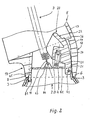
- the cap 50 is designed essentially the same as the cap 20, but has a slot 52 in the region of the trough 33 from the second embodiment is tiltably mounted on a shaft 72.
- the shaft 72 is supported on trestles 73, which protrude from the mounting plate 4 behind the cap 50 in the direction of the mirror housing 5.
- a spring 74 is held at its end near the mirror base on a pin 48 fastened to the mirror base and is suspended with its end near the rocker in a bore 76 in the central part 75 of the rocker 70.
- the rocker 70 is provided with a transverse slot 77, in which the shaft 72 is captured.
- the transverse slot extends transversely to the line of action 78 of the spring 74 in a manner to be described.
- the rocker 70 has a first arm 66 which has an opening 67 near its free end.
- the opening 67 serves as a trap for a locking lug 68 which protrudes from the inside of the front edge section 6 of the mirror housing 5.
- the rocker 70 has a second arm 62, which is opposite the first arm 66 with respect to the central part 75 and dips with its free end into the slot 52.
- FIG. 7 shows the mirror housing 5 in the rear swivel end position, in which the latch 68 is caught in the latch 67 and is supported on the shaft 72 via the first arm 66 and the end of the transverse slot 77 adjacent to the arm 66.
- the mirror housing 5 is held securely in the rear swivel end position.
- the line of action 78 of the spring 74 extends to the right of the shaft 72 as shown in FIG. 7, so that the spring 74 exerts a clockwise torque on the rocker 70, thus holding the first arm 66 against the inside of the front edge section 6.
- the mirror housing 5 is pivoted further back.
- the detent 68 takes the rocker 70 along in such a way that the rocker 70 is pulled over the shaft 72 until the shaft 72 rests on the opposite end of the transverse slot 77.
- the line of action 78 passes through the shaft 72, so that after passing the spring 74 exerts a torque on the rocker 70 in the counterclockwise direction.
- the rocker 70 pivots from the first, locking tilting position shown in FIG. 7 into a second, not shown tilting position under the action of the spring 74.
- the first arm 66 is pulled off the locking lug 68, so that the mirror housing 5 can now freely return to its position of use under the action of the tension spring 7.
- the front edge section 6 sets in on its return path from the region of the rear pivot end position the position of use by taking the second arm 62 with the rocker 70 back into the first tilt position, in which the first arm 66 abuts against the mirror housing 5 from the inside.
- the mirror housing 5 can then pivot back again, the locking lug 68 moving along in the slot 52 and deflecting the rocker 70 against the action of the spring 74 until the locking lug 68 has fallen into the latch 67.
- the transverse slot 67 at the end at which the spring 74 exerts a clockwise torque on the rocker 70 is widened like a bag at 71.
- This measure means that a certain force is required to take the rocker 70 through the mirror housing 5 from the first tilt position shown in FIG. 7, which force can be easily applied by pivoting the mirror housing 5 further towards the vehicle from the rear pivot end position , but prevents the rocker 70 from being taken against the first arm 66 when the latch 68 starts when the mirror housing 5 is pivoted back.
- Fig. 9 shows a modification of the rocker 70 on the first arm 66. Thereafter, the free end of the first arm of the rocker 54 is cranked outwards at 57, which forms a type of locking lug. Correspondingly, a pocket-shaped trap 58 is cut into the front edge section 6 from the inside, into which the first arm 56 of the rocker 54 can dip. The operation of the rocker 54 is otherwise the same as that of the rocker 70.
- brackets 46, 73 on the associated cap 38, 50 and to anchor the spring 74 on a pin 48 which is also mounted in the cap 50. This creates an assembly consisting of a cap and locking member, which is mounted separately from the outside mirror and can then be used as a whole in the outside mirror.
Abstract
Description
Die Erfindung betrifft einen Außenspiegel für Fahrzeuge mit einem an der Karosserie des Fahrzeugs befestigbaren Spiegelfuß und einem am Spiegelfuß mit Federkraft in Gebrauchslage gehaltenen Spiegelgehäuse, wobei ein Rand des Spiegelgehäuses auf einer Schulter des Spiegelfusses ruht und das Spiegelgehäuse um seinen in Fahrtrichtung hinteren Randabschnitt gegen die Federkraft relativ zum Spiegelfuß nach hinten schwenkbar ist.The invention relates to an exterior mirror for vehicles with a mirror base that can be attached to the body of the vehicle and a mirror housing that is held in the position of use on the mirror base with spring force, wherein an edge of the mirror housing rests on a shoulder of the mirror base and the mirror housing around its rear edge section in the direction of travel against the spring force is pivotable backwards relative to the mirror base.
Aus der DE-OS 32 20 893 ist ein Außenspiegel bekannt, bei dem das relativ zur Fahrtrichtung nach rückwärts abgeschwenkte Spiegelgehäuse in einer Schwenkendlage relativ zum Spiegelfuß gehalten ist. Dazu ist am Spiegelfuß ein nach vorne federbelasteter Schwenkarm angelenkt, dessen ausgekehltes freies Ende in der Schwenkendlage den vorderen Spiegelgehäuserand unterfaßt. Beim Durchfahren durch enge Passagen kann das über die Fahrzeugkarosserie seitlich vorstehende Spiegelgehäuse vom Fahrer in die Schwenkendlage abgeklappt werden, so daß sich die für die Durchfahrt des Fahrzeugs erforderliche Durchlaßbreite der Engstelle entsprechend reduziert.From DE-OS 32 20 893 an outside mirror is known in which the mirror housing pivoted backwards relative to the direction of travel is held in a pivoting end position relative to the mirror base. For this purpose, a swivel arm which is spring-loaded to the front is articulated on the mirror base, the fluted free end of which in the swivel end position frames the front edge of the mirror housing. When driving through narrow passages, the mirror housing protruding laterally over the vehicle body can be folded down by the driver into the swivel end position, so that the passage width of the constriction required for the passage of the vehicle is reduced accordingly.
Wenn bei Weiterfahrt das Spiegelgehäuse wieder in die Gebrauchslage zurückgeklappt werden soll, muß der Fahrer den Schwenkarm aus der Arretierstellung nach rückwärts drücken. Dabei kann sich ein Sicherheitsrisiko für den Fahrer insofern ergeben, als seine Finger beim Zurückklappen des Spiegelgehäuses in die Gebrauchslage unter der Wirkung einer üblicherweise stark ausgelegten Zugfeder zwischen vorderem Spiegelgehäuserand und Spiegelfüß eingeklemmt werden können.If the mirror housing is to be folded back into the position of use when driving on, the driver must push the swivel arm backwards out of the locking position. This can result in a safety risk for the driver insofar as his fingers can be pinched between the front edge of the mirror housing and the mirror base when the mirror housing is folded back into the position of use under the effect of a tension spring which is usually designed to be strong.
In der Gebrauchsmusterschrift G 87 11 959.5 ist zur Minderung dieses Sicherheitsrisikos eine lösbare Rastvorrichtung zwischen Spiegelgehäuse und Spiegelfuß vorgesehen, welche einerseits das Spiegelgehäuse in der Schwenkendlage definiert hält und andererseits durch leichten, in die Gebrauchslage gerichteten Stoß auf den äußeren Spiegelgehäuserand gelöst werden kann, so daß der Fahrer nicht mehr genötigt ist, mit seinen Händen in die Öffnung zwischen abgeklapptem Spiegelgehäuse und Spiegelfuß eingreifen zu müssen.In the utility model G 87 11 959.5, a releasable locking device between the mirror housing and the mirror base is provided to reduce this safety risk, which on the one hand holds the mirror housing in the pivoted end position and defines it on the other hand, can be solved by a slight impact on the outer edge of the mirror housing, so that the driver is no longer forced to intervene with his hands in the opening between the folded mirror housing and the mirror base.
Mit dieser Maßname bleibt jedoch die Öffnung zwischen vorderem Spiegelgehäuserand und Spiegelfuß bei nach hinten abgeklapptem Spiegelgehäuse frei zugänglich. Damit bleibt ein Restrisiko einer Verletzungsgefahr bestehen, wenn beispielsweise unbeabsichtigt und unbefugt oder bei der Durchführung von Wartungs- oder Reparaturarbeiten im Vertrauen auf den sicheren Halt des Spiegelgehäuses in der Schwenkendlage durch den Rastmechanismus in die Öffnung eingegriffen wird. Ferner besteht die Gefahr, daß nach dem Anklappen des Spiegelgehäuses an die Fahrzeugkarosserie Fremdpartikel oder Wasser von Waschanlagen in den Bereich zwischen Spiegelfuß und Spiegelgehäuse eingebracht werden.With this measure, however, the opening between the front edge of the mirror housing and the mirror base remains freely accessible when the mirror housing is folded back. This means that there is a residual risk of injury if, for example, unintentional and unauthorized access or when performing maintenance or repair work, the locking mechanism intervenes in the opening by trusting that the mirror housing is securely held in the swivel end position. Furthermore, there is the risk that foreign particles or water from washing systems are introduced into the area between the mirror base and the mirror housing after the mirror housing has been folded onto the vehicle body.
Aus der DE-OS 30 32 392 ist ein schwenkbarer Außenspiegel für Fahrzeuge bekannt, bei dem der vordere Übergang zwischen Spiegelgehäuse und Spiegelfuß von einer elastischen Verkleidung überbrückt ist, welche die beim Abschwenken des Spiegelgehäuses nach hinten entstehende Öffnung zwischen Spiegelgehäuse und Spiegelfuß abdeckt. Diese üblicherweise aus einem Balg aus gummielastischem Werktstoff bestehende Abdeckung ist jedoch relativ aufwendig, weil besondere Maßnahmen zu ihrer dauerhaften Festlegung am Spiegelfuß und Spiegelgehäuse erforderlich sind. Ferner unterliegt der gummiartige Werkstoff Alterungserscheinungen, so daß er unter den Witterungseinflüssen nach längerem Gebrauch brüchig und rissig wird. Schließlich ist der relativ weiche Werkstoff schwerer sauber zu halten als das Kunststoffgehäuse, welches üblicherweise aus einem relativ harten Werkstoff besteht.From DE-OS 30 32 392 a pivoting exterior mirror for vehicles is known, in which the front transition between the mirror housing and the mirror base is bridged by an elastic covering which covers the opening between the mirror housing and the mirror base which is created when the mirror housing is pivoted backwards. However, this cover, which usually consists of a bellows made of rubber-elastic material, is relatively complex because special measures are required to permanently fix it on the mirror base and mirror housing. Furthermore, the rubber-like material is subject to signs of aging, so that it becomes brittle and cracked under the effects of the weather after prolonged use. Finally, the relatively soft material is more difficult to keep clean than the plastic housing, which usually consists of a relatively hard material.
Der Erfindung liegt daher die Aufgabe zugrunde, bei einem Außenspiegel eine Abdeckung für die Öffnung zwischen Spiegelgehäuse und Spiegelfuß zu schaffen, die zweckmäßig aus dem gleichen Werkstoff wie das Spiegelgehäuse hergestellt werden kann, mithin alterungsbeständig ist und eine manuelle Zugriffsmöglichkeit in die Öffnung weitgehend ausschließt.The invention is therefore based on the object to provide a cover for the opening between the mirror housing and the mirror base in an outside mirror, which can be advantageously made of the same material as the mirror housing, therefore is resistant to aging and largely precludes manual access to the opening.
Bei einem Außenspiegel für Fahrzeuge mit einem an der Karosserie des Fahrzeugs befestigbaren Spiegelfuß und einem am Spiegelfuß mit Federkraft in Gebrauchslage gehaltenen Spiegelgehäuse, wobei ein Rand des Spiegelgehäuses auf einer Schulter des Spiegelfusses ruht und das Spiegelgehäuse um seinen in Fahrtrichtung hinteren Randabschnitt gegen die Federkraft relativ zum Spiegelfuß nach hinten schwenkbar ist, ist zur Lösung der genannten Aufgabe erfindungsgemäß vorgesehen, daß am Spiegelfuß eine gebogene, in Gebrauchslage vom Spiegelgehäuse umschlossene Kappe befestigt ist, deren Krümmung auf den hinteren Randabschnitt zentriert ist und gegen deren Außenkontur das Spiegelgehäuse an seinem vorderen Randabschnitt beim Schwenken anliegt. Damit bleibt die Kappe in Gebrauchsstellung des Spiegelgehäuses vor Witterungseinflüssen befreit und tritt auch ästhetisch nach außen nicht in Erscheinung. Ferner kann die Kappe aus einem einfachen Kunststoff-Spritzteil hergestellt werden. Schließlich ermöglicht sie die volle Abdeckung der Öffnung zwischen Spiegelgehäuse und Spiegelfuß beim Abschwenken des ersteren.In the case of an exterior mirror for vehicles with a mirror base which can be fastened to the body of the vehicle and a mirror housing which is held in the position of use on the mirror base with spring force, an edge of the mirror housing resting on a shoulder of the mirror base and the mirror housing around its rear edge section in the direction of travel against the spring force relative to Mirror base is pivotable to the rear, is provided according to the invention to solve the problem that a curved, in the use position enclosed by the mirror housing cap is attached, the curvature of which is centered on the rear edge portion and against the outer contour of the mirror housing at its front edge portion when pivoting is present. In this way, the cap remains free from the weather when the mirror housing is in use and also does not appear aesthetically. Furthermore, the cap can be made from a simple molded plastic part. Finally, it enables the opening between the mirror housing and mirror base to be fully covered when the former is pivoted away.
Wenn in üblicher Weise das Spiegelgehäuse relativ zum Spiegelfuß auch nach vorne abschwenkbar ist, empfiehlt es sich in Weiterbildung der Erfindung, die Kappe in der Nähe eines vorderen Schulterabschnittes am Spiegelfuß anzulenken und entweder mittels einer Feder gegen das Spiegelgehäuse anzudrücken oder an der Kappe einen Fuß vorzusehen, mit dem sie sich beim Rückwärtsschwenken auf dem Spiegelfuß abstützt. Diese Ausführungsformen ermöglichen eine Mitnahme der Kappe beispielsweise durch die das Spiegelgehäuse in Gebrauchslage haltende Zugfeder beim Abschwenken des Spiegelgehäuses nach vorne.If the mirror housing can also be swiveled forward relative to the mirror base in a conventional manner, it is advisable in a further development of the invention to link the cap near a front shoulder section on the mirror base and either press it against the mirror housing by means of a spring or to provide a foot on the cap with which it is supported on the mirror base when swiveling backwards. These embodiments enable the cap to be taken along, for example, by the tension spring which holds the mirror housing in the position of use when the mirror housing is pivoted forwards.
In einer besonders bevorzugten Ausgestaltung der Erfindung kann an der Kappe ein Sperrorgan ausgebildet sein, welches das Spiegelgehäuse in einer bezüglich der Fahrtrichtung hinteren Schwenkendlage lösbar ergreift. Dieses Sperrorgan kann dadurch in die Kappenform integriert sein, daß eine aus der Außenkontur der Kappe vorstehende Nase vorgesehen ist, welche den vorderen Randabschnitt in der Schwenkendlage unterfaßt. Aus der definierten Schwenkendlage kann das Spiegelgehäuse dann durch leichten Stoß auf die äußeren Partien des Spiegelgehäuses vom Fahrersitz aus befreit werden, woraufhin das Spiegelgehäuse selbsttätig von der Zugfeder in seine Gebrauchslage zurückgeschwenkt wird.In a particularly preferred embodiment of the invention, a locking member can be formed on the cap, which detachably grips the mirror housing in a rear pivoting end position with respect to the direction of travel. This blocking organ can be integrated into the cap shape in that a nose protruding from the outer contour of the cap is provided, which underlies the front edge section in the pivot end position. From the defined swivel end position, the mirror housing can then be freed from the driver's seat by a light impact on the outer parts of the mirror housing, whereupon the mirror housing is automatically pivoted back into its position of use by the tension spring.
Für die Ausbildung des Sperrorgans kommen neben der erwähnten Nase mehrere alternative Ausführungsformen erfindungsgemäß in Betracht. So kann das Sperrorgan ein einen Absatz des Spiegelgehäuses unterfassender Riegel sein, welcher innerhalb der Kappe befestigt ist und aus einer Öffnung der Kappe wenig vorsteht, wobei zur Erleichterung der Abschwenkbewegung des Spiegelgehäuses nach hinten der Riegel zweckmäßig gegen Federdruck nach rückwärts ausweichen kann.In addition to the nose mentioned, several alternative embodiments are possible according to the invention for the formation of the locking member. So the locking member can be a paragraph of the mirror housing locking bolt, which is fastened within the cap and protrudes little from an opening of the cap, whereby to facilitate the pivoting movement of the mirror housing backwards the bolt can dodge backwards against spring pressure.
In einer anderen Ausführungsform besitzt das Sperrorgan die Form einer Wippe, welche von einer Feder in jeweils einer von zwei Kipplagen gehalten ist. In der ersten Kipplage fällt bei Erreichen der Schwenkendlage eine an der Wippe oder dem Spiegelgehäuse ausgebildete Raste in eine Falle und hält auf diese Weise das abgeschwenkte Spiegelgehäuse in der Schwenkendlage. Zum Lösen aus dieser Schwenkendlage wird das Spiegelgehäuse noch ein kurzes Stück weiter zur Fahrzeugkarosserie angeschwenkt, wodurch die Wippe in ihre zweite Kipplage überführt wird, in welcher die Raste aus der Falle freikommt, so daß das Spiegelgehäuse von der Zugfeder in seine Gebrauchslage zurückgeführt werden kann. Bei diesem Rückschwenken stellt das Spiegelgehäuse die Wippe in ihrer erste Kipplage um, so daß diese zur erneuten Arretierung des Spiegelgehäuses in seiner hinteren Schwenkendlage vorbereitet ist.In another embodiment, the locking member is in the form of a rocker, which is held by a spring in one of two tilt positions. In the first tilt position, when the pivot end position is reached, a catch formed on the rocker or the mirror housing falls into a trap and in this way holds the pivoted mirror housing in the pivot end position. To release from this swivel end position, the mirror housing is pivoted a short distance further to the vehicle body, whereby the rocker is transferred to its second tilt position, in which the catch is released from the trap, so that the mirror housing can be returned to its position of use by the tension spring. During this swiveling back, the mirror housing changes the rocker in its first tilt position, so that it is prepared for locking the mirror housing in its rear swiveling end position.
Die bevorzugten Ausgestaltungen der Erfindung sind im einzelnen in den Unteransprüchen angegeben.The preferred embodiments of the invention are specified in the subclaims.
Nachstehend wird die Erfindung anhand der in der beigefügten Zeichnung dargestellten Ausführungsbeispiele im einzelnen beschrieben. Es zeigen:
- Fig 1: einen horizontalen Querschnitt durch Spiegelgehäuse und an einer Fahrzeugkarosserie montierten Spiegelfuß;
- Fig 2: einen Querschnitt durch den spiegelfußnahen Teil des Spiegelgehäuses mit Kappe in Gebrauchslage;
- Fig 3: einen Querschnitt durch den spiegelfußnahen Teil des Spiegelgehäuses mit Kappe in hinterer Schwenkendlage;
- Fig 4: einen Querschnitt durch den spiegelfußnahen Teil des Spiegelgehäuses in vorderer Schwenklage;
- Fig 5: eine der Fig. 3 ähnliche Darstellung einer zweiten Ausführungsform eines Sperrorgans;
- Fig 6: eine Draufsicht auf den Spiegelfusses mit Kappe und Sperrorgan gemäß Fig. 5 nach Abnahme des Spiegelgehäuses;
- Fig 7: eine der Fig. 3 ähnliche Darstellung einer dritten Ausführungsform;
- Fig 8: eine vergrößerte Ausschnittsdarstellung aus Fig. 7; und
- Fig 9: eine vergrößerte Ausschnittsdarstellung aus Fig. 7, jedoch mit einer anderen Ausführungsform des Sperrorgans.
- 1 shows a horizontal cross section through mirror housing and mirror base mounted on a vehicle body;
- 2 shows a cross section through the part of the mirror housing near the mirror base with cap in the position of use;
- 3 shows a cross section through the part of the mirror housing near the mirror base with a cap in the rear pivoting end position;
- 4 shows a cross section through the part of the mirror housing near the mirror base in the front pivot position;
- 5: a representation similar to FIG. 3 of a second embodiment of a locking member;
- 6: a plan view of the mirror base with cap and locking element according to FIG. 5 after removal of the mirror housing;
- 7: a representation similar to FIG. 3 of a third embodiment;
- FIG. 8: an enlarged detail representation from FIG. 7; and
- FIG. 9: an enlarged detail view from FIG. 7, but with another embodiment of the blocking member.
Zur Erläuterung des technischen Hintergrundes der Erfindung zeigt Fig. 1 zunächst einen Außenspiegel bekannter Bauart. An einer schematisch gestrichelt dargestellten Fahrzeugkarosserie 1 ist ein Spiegelfuß 2 in nicht dargestellter Weise befestigt. An der von der Fahrzeugkarosserie 1 abgewandten Seite besitzt der Spiegelfuß 2 eine Montageplatte 4, welche, zur Fahrzeugkarosserie 1 hin abgesetzt, von einer um die Montageplatte 4 umlaufenden nach außen vorstehenden Schulter 3 umgeben ist. Ein Spiegelgehäuse 5 besitzt einen spiegelfußnahen am Ende ballig geformten Rand 18, von dem in Fig. 1 der vordere Randabschnitt 6 und der hintere Randabschnitt 8 zu erkennen sind. Die Bezeichnungen "vorne" und "hinten" beziehen sich auf die mit dem Pfeil 10 angegebene Fahrtrichtung des Fahrzeugs. Die Randabschnitte 6, 8 umgreifen die Montageplatte 4 und stehen in der in Fig. 1 dargestellten Gebrauchslage des Spiegelgehäuses 5 auf entsprechenden Partien der Schulter 3 auf.To explain the technical background of the invention, FIG. 1 first shows an exterior mirror of a known type. A
An der Montageplatte 4 ist ein Ende einer kräftigen Zugfeder 7 befestigt, deren in dem Spiegelgehäuse 5 befindliches Ende in eine Öse 11 einer Tragplatte 15 eingehängt ist. Die Tragplatte 15 ist an der vorderen Wand 13 des Spiegelgehäuses 5 über Stützen befestigt, von denen eine spiegelfußferne Stütze 14 in Fig. 1 angegeben ist. In nicht dargestellter Weise ist ein Spiegelglas 9 auf der Tragplatte 15 in üblicher Weise mittels vom Fahrzeuginneren aus über nicht dargestellte, sich durch den Spiegelfuß 2 und eine Öffnung 16 im Spiegelgehäuse 5 erstreckende Betätigungsorgane verstellbar gehalten. In der Nähe des vorderen Randabschnittes 6 ist an der Montageplatte 4 ein sich in das Innere des Spiegelgehäuses 5 erstreckender Arm angelenkt und von einer Feder 17 gegen die Innenseite der Wand 13 gehalten.On the
Zu weiteren Einzelheiten und der Wirkungsweise des Abschwenkens des Spiegelgehäuses 5 relativ zum Spiegelfuß 2 nach vorne oder hinten wird auf die DE-OS 32 20 893 Bezug genommen.For further details and the operation of the pivoting of the
Gemäß der in Fig. 2 bis 4 dargestellten ersten Ausführungsform der Erfindung ist eine im Ganzen mit 20 bezeichnete Kappe innerhalb des Randes 18 in einem Bereich der Montageplatte 4 des Spiegelfusses 2 angelenkt, der dem vorderen Randabschnitt 6 benachbart ist. Dazu weist die Montageplatte 4 ein Ausschnitt 41 auf, in welchen ein unteres Ende 21 der Kappe 20 hineinragt und dort auf einem Zapfen 42 um eine zur Ebene der Fig. 2 senkrechte, bei an das Fahrzeug anmontiertem Außenspiegel also im wesentlichen vertikale der Achse schwenkbar gehalten ist. Die Kappe 20, die ein einteiliges Bauteil ist und aus dem gleichen Kunststoff besteht wie das Spiegelgehäuse 5, hat eine gebogene oder gewölbte Form, deren Krümmung auf den hinteren Randabschnitt 8 zentriert ist. Die Schalenform der Kappe 20 richtet sich im einzelnen nach der äußeren Form des Randes 18 derart, daß die Außenkontur 22 der Kappe 20 durch die Gestalt der Bahn definiert ist, die der vordere Randabschnitt 6 beim Abschwenken des Spiegelgehäuses 5 nach hinten durchläuft.According to the first embodiment of the invention shown in FIGS. 2 to 4, a cap designated as a whole by 20 is within the
An die Kappe 20 ist eine innere Verdickung 23 angeformt, welche eine Tasche 24 zur Aufnahme und zum Halten einer Druckfeder 25 aufweist. Die Druckfeder 25 steht mit ihrem freien Ende aus der Tasche 24 vor und kann sich auf der Oberseite der Montageplatte 4 des Spiegelfusses 2 abstützen.An inner thickening 23 is formed on the
Aus der Außenkontur 22 der Kappe 20 steht in der Nähe ihres spiegelfussfernen Endes eine Nase 26 nach außen vor, deren Funktion noch erläutert wird.From the
Ferner ist in den Figuren 2 bis 4 zu erkennen, daß aus der Montageplatte 4 etwa mittig ein Anker 43 mit einem Auge 44 zum Spiegelgehäuse 5 hin vorsteht. In das Auge 44 ist das spiegelfußnahe Ende 19 der Zugfeder 7 eingehängt.It can also be seen in FIGS. 2 to 4 that an
An dem hinteren Randabschnitt 8 ist ein stiftförmiger Fortsatz 81 ausgebildet, welcher in einen hinteren Ausschnitt 45 in der hinteren Seitenflanke der Montageplatte 4 eintaucht.A pin-shaped
Bei der in Fig. 2 ausschnittweise dargestellten Gebrauchslage des Spiegelgehäuses 5 ist die die Kappe 20 und die Druckfeder 25 umfassende Baugruppe ganz vom Rand 18 des Spiegelgehäuses 5 und somit von außen nicht sichtbar. Beim Abschwenken des Spiegelgehäuses 5 nach hinten um eine Achse, die im wesentlichen durch die Auflage des hinteren Randabschnittes 8 auf dem hinteren Teil der Schulter 3 bestimmt ist, gleitet der vordere Randabschnitt 6 auf einem ersten Teil 27 der Außenkontur 22 entlang, welcher gegenüber dem umgebenden Teil 28 der Außenkontur rippenartig mit nach oben zunehmender Stärke vorsteht und in der Nase 26 endet. Während des Entlanggleitens des vorderen Randabschnittes 6 wird die Kappe 20 um den Zapfen 42 in Richtung auf die Montageplatte 4 gegen die Wirkung der sich auf dieser dann abstützenden Druckfeder 25 gedrückt. Hat im Zuge der fortschreitenden Schwenkbewegung nach hinten der vordere Randabschnitt 6 die Nase 26 passiert, springt die Kappe 20 soweit nach vorne, daß der obere Teil 29 ihrer Außenkontur 22 jetzt von innen gegen den Rand 18 anliegt. Gleichzeitig sichert das Eindringen des Fortsatzes 81 durch den Ausschnitt 45 in den Spiegelfuß 2 das Spiegelgehäuse 5 an einer Verschiebung relativ zum Spiegelfuß 2 nach unten oder oben. Das Spiegelgehäuse 5 kann in Richtung auf seine Gebrauchslage unter der Wirkung der Zugfeder 7 jetzt nur noch bis zu seiner in Fig. 3 dargestellten hinteren Schwenkendlage zurückkehren, welche durch Unterfassen des vorderen Randabschnittes 6 durch die Nase 26 bestimmt ist. Aus dieser stabilen Schwenkendlage kann das Spiegelgehäuse durch kurzen Schlag oder Druck von Hand auf seinen äußeren Teil 51 befreit werden, wodurch der vordere Randabschnitt 6 uber die Nase 26 nach außen hinausgehoben wird, was durch eine entsprechende Größe des hinteren Ausschnitts 45 ermöglicht wird. Danach kann das Spiegelgehäuse 5 unter der Wirkung der Zugfeder 7 selbsttätig in die in Fig. 2 dargestellte Gebrauchslage zurückkehren.In the position of use of the
Man erkennt jedenfalls, daß die Form der Kappe die Öffnung, die zwischen vorderem Randabschnitt 6 und Montageplatte 4 des Spiegelfusses 2 bei der nach hinten erfolgender Schwenkbewegung des Spiegelgehäuses entsteht, von der Kappe 20 weitgehend verschlossen ist. Die seitliche Ausdehnung der Kappe 20 unterliegt dabei keinen Beschränkungen, so daß diese so groß gewählt werden kann, daß die genannte Öffnung bis zur hinteren Schwenkendlage praktisch vollständig von außen verschlossen bleibt.In any case, it can be seen that the shape of the cap, the opening which is formed between the
Bei dem Abschwenken des Spiegelgehäuses hebt gemäß Fig. 4 der hintere Randabschnitt 8 mit Fortsatz 81 vom hinteren Teil der Schulter 3 ab, während der vordere Randabschnitt 6 auf dem vorderen Teil der Schulter 3 abrollt. Die Kappe 20 wird bei dieser nach vorne gerichteten Schwenkbewegung von der Zugfeder 7 mit nach vorne geschwenkt, stört jedoch sonst die zwangsläufigen Bewegungen der Zugfeder und der sonstigen Verstellorgane für den Spiegel 9 nicht.4, the
Die in den Figuren 5 und 6 dargestellte zweite Ausführungsform der Erfindung unterscheidet sich von der ersten, vorstehend beschriebenen Ausführungsform dadurch, daß statt der aus der Außenkontur 22 der Kappe 20 vorspringenden Nase ein separater Riegel 30 vorgesehen ist, welcher auf einer zum Zapfen 42 im wesentlichen parallelen Welle 31 schwenkbar gelagert ist. Der Riegel 30 läuft oben zu einem schmalen Grat 32 zu, welcher in eine in die Außenkontur 34 eingesenkte Rinne 33 vorsteht. Von dem Riegel 30 reicht an dem von dem Grat 32 abgewandten Ende eine Schürze 35 in Richtung auf die Montageplatte 4 herab. In einem aus der Montageplatte 4 vorstehenden Bock 46 ist eine Einsenkung 46 ausgeformt, deren Öffnung auf die Schürze 35 zuweist. In der Einsenkung 47 ist eine Druckfeder 36 beherbergt, welche sich am Boden der Einsenkung 47 abstützt und gegen die Schürze 35 anliegt. Die Höhe des Bockes 46 über der Montageplatte 4 ist so gewählt, daß ein Absatz 37, der am Riegel 30 zwischen der Welle 31 und der Kappe 38 ausgebildet ist, in der in Fig. 5 dargestellten Arretierstellung des Riegels 30 auf der Oberseite des Bocks 46 als Anschlag aufsitzt.The second embodiment of the invention shown in FIGS. 5 and 6 differs from the first embodiment described above in that, instead of the nose protruding from the
Die Kappe 38 ist im oberen Bereicht der Rinne 33 bei 39 geschlitzt, gleicht im übrigen der Kappe 20 aus dem ersten Ausführungsbeispiel.The
Das Spiegelgehäuse 5 besitzt innerhalb seines vorderen Randabschnitts 6 eine nach innen vorspringende Schulter 61, die soweit vorsteht, daß sie ganz in die Rinne 31 eintaucht und in der hinteren Schwenkendlage von dem Riegel 30 mit dessen Grat 32 hintergriffen werden kann.The
Wird das Spiegelgehäuse 5 nach der zweiten Ausführungsform nach rückwärts abgeschwenkt, lenkt die Innenseite der Nase 61, die selbstverständlich nicht breiter ist als die Breite der Rinne 33, zunächst den Riegel 30 nach hinten gegen die Wirkung der Feder 36 zur Seite, bis der Riegel 30 in die in Fig. 5 dargestellten Arretierstellung hinter die Schulter 61 vorspringen kann. Das abgeschwenkte Spiegelgehäuse 5 kann dann in seine Gebrauchslage nur bis in die in Fig. 5 dargestellte hintere Schwenkendlage zurückkehren, bei der die Schulter 61 gegen den Grat 32 anliegt. Zum Lösen wird durch manuellen Druck auf die Partie 51 des Spiegelgehäuses die Nase 61 über den Grat 32 hinweggehoben, so daß das Spiegelgehäuse wieder in seine Gebrauchslage zurückkehren kann.If the
In der dritten Ausführungsform gemäß Fig. 7 ist die Kappe 50 im wesentlichen gleich gestaltet wie die Kappe 20, besitzt jedoch im Bereich der Rinne 33 aus der zweiten Ausführungsform einen Schlitz 52. Das Sperrorgan 70 hat in der dritten Ausführungsform die Gestalt einer Wippe, welche auf einer Welle 72 kippbar gelagert ist. Die Welle 72 ist Böcken 73 gehalten, die aus der Montageplatte 4 hinter der Kappe 50 in Richtung auf das Spiegelgehäuse 5 vorstehen. Eine Feder 74 ist an ihrem spiegelfußnahen Ende an einem am Spiegelfuß befestigten Zapfen 48 gehalten und mit ihrem wippennahen Ende in eine Bohrung 76 im mittleren Teil 75 der Wippe 70 eingehängt. Im mittleren Teil 75 ist die Wippe 70 mit einem Querschlitz 77 versehen, in welchem die Welle 72 eingefangen ist. Der Quereschlitz erstreckt sich quer zur Wirkungslinie 78 der Feder 74 in noch zu beschreibender Weise.In the third embodiment according to FIG. 7, the
Die Wippe 70 besitzt einen ersten Arm 66, der in der Nähe seines freien Endes einen Durchbruch 67 aufweist. Der Durchbruch 67 dient als Falle für eine Rastnase 68, welche aus der Innenseite des vorderen Randabschnittes 6 des Spiegelgehäuses 5 vorsteht.The
Die Wippe 70 besitzt einen zweiten Arm 62, der bezüglich des mittleren Teils 75 dem ersten Arm 66 gegenüber liegt und mit seinem freien Ende in den Schlitz 52 eintaucht.The
Fig. 7 zeigt das Spiegelgehäuse 5 in der hinteren Schwenkendlage, bei der die Rastnase 68 in der Falle 67 eingefangen ist und sich über den ersten Arm 66 und das dem Arm 66 benachbarte Ende des Querschlitzes 77 auf der Welle 72 abstützt. Somit wird das Spiegelgehäuse 5 in der hinteren Schwenkendlage sicher gehalten. Die Wirkungslinie 78 der Feder 74 verläuft gemäß Fig. 7 rechts von der Welle 72, so daß die Federe 74 auf die Wippe 70 ein Drehmoment im Urzeigersinn ausübt, mithin den ersten Arm 66 gegen die Innenseite des vorderen Randabschnittes 6 hält. Zum Lösen des Spiegelgehäuses 5 aus der hinteren Schwenkendlage wird das Spiegelgehäuse 5 noch weiter nach hinten abgeschwenkt. Bei dieser weitergehenden Schwenkbewegung nimmt die Rastnase 68 die Wippe 70 dergestalt mit, daß die Wippe 70 über die Welle 72 gezogen wird, bis die Welle 72 am gegenüberliegenden Ende des Querschlitzes 77 anliegt. Dabei passiert die Wirklinie 78 die Welle 72, so daß nach dem Passieren die Feder 74 ein Drehmoment auf die Wippe 70 in Gegenrichtung des Uhrzeigers ausübt. Dies hat zur Folge, daß die Wippe 70 aus der in Fig. 7 dargestellten ersten, arretierenden Kipplage in eine zweite, nicht dargestellte Kipplage unter der Wirkung der Feder 74 verschwenkt. Dadurch wird der erste Arm 66 von der Rastnase 68 abgezogen wird, so daß das Spiegelgehäuse 5 jetzt ungehindert unter der Wirkung der Zugfeder 7 in seine Gebrauchslage zurückkehren kann. Da in der zweiten Kipplage, die durch Freigabe der Rastnase 68 aus der Falle 67 bestimmt ist, der zweite Arm 62 aus dem Schlitz 52 in den Rückkehrweg des vorderen Randabschnittes ragt, stellt der vordere Randabschnitt 6 auf seinem Rückkehrweg von dem Bereich der hinteren Schwenkendlage in die Gebrauchslage durch Mitnahme des zweiten Armes 62 die Wippe 70 wieder in die erste Kipplage um, bei der der erste Arm 66 von innen gegen das Spiegelgehäuse 5 anliegt. Das Spiegelgehäuse 5 kann dann erneut nach hinten abschwenken, wobei die Rastnase 68 in dem Schlitz 52 entlangfährt und die Wippe 70 gegen die Wirkung der Feder 74 solange auslenkt, bis die Rastnase 68 in die Falle 67 eingefallen ist.FIG. 7 shows the
Wie Fig. 8 zeigt ist der Querschlitz 67 an demjenigen Ende, an welchem die Feder 74 ein in Richtung des Uhrzeigers gerichtetes Drehmoment auf die Wippe 70 ausübt, sackartig bei 71 erweitert. Diese Maßname bewirkt, daß zur Mitnahme der Wippe 70 durch das Spiegelgehäuse 5 aus der in Fig. 7 dargestellten ersten Kipplage heraus eine gewisse Kraft erforderlich ist, die durch das weitere Heranschwenken des Spiegelgehäuses 5 an das Fahrzeug aus der hinteren Schwenkendlage heraus leicht aufgebracht werden kann, jedoch verhindert, daß die Wippe 70 bereits beim Anlaufen der Rastnase 68 gegen den ersten Arm 66 während des Zurückschwenkens des Spiegelgehäuses 5 mitgenommen wird.As shown in FIG. 8, the
Fig. 9 zeigt eine Abwandlung der Wippe 70 am ersten Arm 66. Danach ist das freie Ende des ersten Arms der Wippe 54 nach außen bei 57 abgekröpft, welches ein Art Rastnase bildet. Entsprechend ist von der Innenseite in den vorderen Randabschnitt 6 eine taschenförmige Falle 58 eingeschnitten, in welche der erste Arm 56 der Wippe 54 eintauchen kann. Die Wirkungsweise der Wippe 54 gleicht im übrigen derjenigen der Wippe 70.Fig. 9 shows a modification of the
Es liegt im Rahmen der Erfindung, die Böcke 46, 73 an die zugehörige Kappe 38, 50 anzuformen und die Feder 74 an einem Zapfen 48 zu verankern, der ebenfalls in der Kappe 50 gelagert ist. Damit ist eine Baugruppe bestehend aus Kappe und Sperrorgan geschaffen, welche separat vom Außenspiegel montiert und dann als Ganzes in den Außenspiegel eingesetzt werden kann.It is within the scope of the invention to form the
Claims (11)
Applications Claiming Priority (2)
| Application Number | Priority Date | Filing Date | Title |
|---|---|---|---|
| DE8804802U DE8804802U1 (en) | 1988-04-12 | 1988-04-12 | |
| DE8804802U | 1988-04-12 |
Publications (3)
| Publication Number | Publication Date |
|---|---|
| EP0337364A2 true EP0337364A2 (en) | 1989-10-18 |
| EP0337364A3 EP0337364A3 (en) | 1991-02-06 |
| EP0337364B1 EP0337364B1 (en) | 1994-09-28 |
Family
ID=6822836
Family Applications (1)
| Application Number | Title | Priority Date | Filing Date |
|---|---|---|---|
| EP89106344A Expired - Lifetime EP0337364B1 (en) | 1988-04-12 | 1989-04-11 | Breakaway exterior mirror for vehicles |
Country Status (7)
| Country | Link |
|---|---|
| US (1) | US4907869A (en) |
| EP (1) | EP0337364B1 (en) |
| AT (1) | ATE112215T1 (en) |
| CA (1) | CA1322681C (en) |
| DE (2) | DE8804802U1 (en) |
| ES (1) | ES2060683T3 (en) |
| MX (1) | MX171658B (en) |
Cited By (2)
| Publication number | Priority date | Publication date | Assignee | Title |
|---|---|---|---|---|
| US5549481A (en) * | 1993-06-04 | 1996-08-27 | Framatome Connectors International | Connector assembly for printed circuit boards |
| DE29620696U1 (en) * | 1996-11-28 | 1998-04-02 | Hohe Gmbh & Co Kg | Outside mirrors for a motor vehicle |
Families Citing this family (8)
| Publication number | Priority date | Publication date | Assignee | Title |
|---|---|---|---|---|
| DE8813505U1 (en) * | 1988-10-27 | 1989-03-23 | Hohe Kg, 6981 Collenberg, De | |
| FR2642380B1 (en) * | 1989-01-27 | 1994-06-24 | Harman Automative | FOLDING MIRROR IN PARKING POSITION AND EJECTION POSITION |
| DE8913032U1 (en) * | 1989-11-04 | 1990-03-22 | Eugen Zipperle Gmbh & Co Kg, 7144 Asperg, De | |
| DE4017028C2 (en) * | 1990-05-26 | 1993-10-21 | Zipperle Eugen Gmbh & Co Kg | Outside mirrors for motor vehicles |
| ES2029188A6 (en) * | 1991-03-13 | 1992-07-16 | Fico Mirrors Sa | Retraction mechanism for exterial rearview mirrors of motor vehicles |
| US5477390A (en) * | 1993-08-16 | 1995-12-19 | Lowell Engineering Corp. | Mirror assembly powered into rearwardly folded position against reversing spring bias |
| US5477391A (en) * | 1993-08-16 | 1995-12-19 | Lowell Engineering Corp. | Mirror assembly movable into rearwardly folded position with reversing spring bias |
| US6733144B2 (en) * | 2002-09-27 | 2004-05-11 | Intel Corporation | Shock protectors for micro-mechanical systems |
Citations (3)
| Publication number | Priority date | Publication date | Assignee | Title |
|---|---|---|---|---|
| DE3032392A1 (en) * | 1980-08-28 | 1982-03-04 | Hohe Kg, 6981 Collenberg | Spring-back mounting for exterior driving mirror - has flexible cowl between mirror and mounting for reduced drag |
| DE3220893A1 (en) * | 1982-06-03 | 1983-12-08 | Hohe Kg, 6981 Collenberg | Exterior rearview mirror with restraining lever for vehicles |
| DE8711959U1 (en) * | 1987-09-03 | 1987-12-23 | Hohe Kg, 6981 Collenberg, De |
Family Cites Families (1)
| Publication number | Priority date | Publication date | Assignee | Title |
|---|---|---|---|---|
| GB8525778D0 (en) * | 1985-10-18 | 1985-11-20 | Britax Wingard Ltd | Exterior rear view mirrors |
-
1988
- 1988-04-12 DE DE8804802U patent/DE8804802U1/de not_active Expired
-
1989
- 1989-04-11 AT AT89106344T patent/ATE112215T1/en not_active IP Right Cessation
- 1989-04-11 US US07/336,123 patent/US4907869A/en not_active Expired - Lifetime
- 1989-04-11 EP EP89106344A patent/EP0337364B1/en not_active Expired - Lifetime
- 1989-04-11 DE DE58908427T patent/DE58908427D1/en not_active Expired - Fee Related
- 1989-04-11 ES ES89106344T patent/ES2060683T3/en not_active Expired - Lifetime
- 1989-04-12 MX MX015636A patent/MX171658B/en unknown
- 1989-04-12 CA CA000596501A patent/CA1322681C/en not_active Expired - Fee Related
Patent Citations (3)
| Publication number | Priority date | Publication date | Assignee | Title |
|---|---|---|---|---|
| DE3032392A1 (en) * | 1980-08-28 | 1982-03-04 | Hohe Kg, 6981 Collenberg | Spring-back mounting for exterior driving mirror - has flexible cowl between mirror and mounting for reduced drag |
| DE3220893A1 (en) * | 1982-06-03 | 1983-12-08 | Hohe Kg, 6981 Collenberg | Exterior rearview mirror with restraining lever for vehicles |
| DE8711959U1 (en) * | 1987-09-03 | 1987-12-23 | Hohe Kg, 6981 Collenberg, De |
Cited By (2)
| Publication number | Priority date | Publication date | Assignee | Title |
|---|---|---|---|---|
| US5549481A (en) * | 1993-06-04 | 1996-08-27 | Framatome Connectors International | Connector assembly for printed circuit boards |
| DE29620696U1 (en) * | 1996-11-28 | 1998-04-02 | Hohe Gmbh & Co Kg | Outside mirrors for a motor vehicle |
Also Published As
| Publication number | Publication date |
|---|---|
| ATE112215T1 (en) | 1994-10-15 |
| DE58908427D1 (en) | 1994-11-03 |
| EP0337364A3 (en) | 1991-02-06 |
| EP0337364B1 (en) | 1994-09-28 |
| US4907869A (en) | 1990-03-13 |
| CA1322681C (en) | 1993-10-05 |
| DE8804802U1 (en) | 1988-09-01 |
| MX171658B (en) | 1993-11-10 |
| ES2060683T3 (en) | 1994-12-01 |
Similar Documents
| Publication | Publication Date | Title |
|---|---|---|
| DE69831430T2 (en) | Vehicle seat with a neck protection device in a rear impact | |
| DE2655535C3 (en) | Articulated fittings for motor vehicle seats | |
| DE4331884B4 (en) | Covering device for a cosmetic mirror | |
| EP0096154A2 (en) | Sun visor, especially for vehicles | |
| EP0393586B1 (en) | Device for the releasable fixing of a shoe to a bicycle pedal | |
| EP0337364B1 (en) | Breakaway exterior mirror for vehicles | |
| DE3444216A1 (en) | Headrest | |
| DE3325833A1 (en) | DOOR MIRROR DEVICE FOR AUTOMOBILES | |
| EP0359962A1 (en) | Seat, particularly a motor car seat | |
| EP0324926B1 (en) | Folding exterior mirror for a vehicle | |
| DE2904616A1 (en) | DEVICE FOR HOLDING THE DOOR OF A MOTOR VEHICLE | |
| DE3521527A1 (en) | WIPER ARMS, ESPECIALLY FOR WINDOW CLEANING SYSTEMS FOR MOTOR VEHICLES | |
| DE3923932A1 (en) | Vehicular exterior mirror assembly kit with adaptor plate - which supports mirror in exterior housing and is attached pivotably to two fixing points on baseplate | |
| EP0190715B1 (en) | Vehicle swing door | |
| DE2309956C2 (en) | Snap hinge for furniture doors | |
| DE2802502A1 (en) | EXTERIOR REAR MIRROR FOR A MOTOR VEHICLE | |
| DE10012971A1 (en) | Interior rear view mirror for fitting on inside of motor vehicle's windscreen has first and second means of connection so that when released enable support foot to pivot around respective axes of connections | |
| DE3530108C1 (en) | Wiper arm, in particular for motor vehicle windscreen wiper systems | |
| DE3231418C2 (en) | Securing device on vehicles for securing a sliding door which can be moved into the area of a filler neck of a fuel tank during refueling | |
| DE3803642A1 (en) | Footrest on a motor vehicle | |
| DE3390395T1 (en) | Windshield wiper system with a rocker device attached to the wiper blade by means of an adapter | |
| EP0297284A2 (en) | Exterior rear view mirror | |
| DE2406381A1 (en) | Dipping interior driving mirror - with tilt operation controlled by twisting eccentric cam to retain setting | |
| EP0298471A1 (en) | Under ride protection for the rearward end of a tipper vehicle with a superstructure tippable about a rearward lateral axis | |
| DE3609449A1 (en) | Inside rear view mirror for motor vehicles |
Legal Events
| Date | Code | Title | Description |
|---|---|---|---|
| PUAI | Public reference made under article 153(3) epc to a published international application that has entered the european phase |
Free format text: ORIGINAL CODE: 0009012 |
|
| AK | Designated contracting states |
Kind code of ref document: A2 Designated state(s): AT BE CH DE ES FR GB IT LI LU NL SE |
|
| PUAL | Search report despatched |
Free format text: ORIGINAL CODE: 0009013 |
|
| AK | Designated contracting states |
Kind code of ref document: A3 Designated state(s): AT BE CH DE ES FR GB IT LI LU NL SE |
|
| 17P | Request for examination filed |
Effective date: 19910724 |
|
| 17Q | First examination report despatched |
Effective date: 19920930 |
|
| GRAA | (expected) grant |
Free format text: ORIGINAL CODE: 0009210 |
|
| AK | Designated contracting states |
Kind code of ref document: B1 Designated state(s): AT BE CH DE ES FR GB IT LI LU NL SE |
|
| REF | Corresponds to: |
Ref document number: 112215 Country of ref document: AT Date of ref document: 19941015 Kind code of ref document: T |
|
| REF | Corresponds to: |
Ref document number: 58908427 Country of ref document: DE Date of ref document: 19941103 |
|
| GBT | Gb: translation of ep patent filed (gb section 77(6)(a)/1977) |
Effective date: 19941027 |
|
| REG | Reference to a national code |
Ref country code: ES Ref legal event code: FG2A Ref document number: 2060683 Country of ref document: ES Kind code of ref document: T3 |
|
| ET | Fr: translation filed | ||
| ITF | It: translation for a ep patent filed |
Owner name: UFFICIO TECNICO ING. A. MANNUCCI |
|
| EAL | Se: european patent in force in sweden |
Ref document number: 89106344.8 |
|
| PG25 | Lapsed in a contracting state [announced via postgrant information from national office to epo] |
Ref country code: LU Free format text: LAPSE BECAUSE OF NON-PAYMENT OF DUE FEES Effective date: 19950430 Ref country code: LI Effective date: 19950430 Ref country code: CH Effective date: 19950430 |
|
| PLBE | No opposition filed within time limit |
Free format text: ORIGINAL CODE: 0009261 |
|
| STAA | Information on the status of an ep patent application or granted ep patent |
Free format text: STATUS: NO OPPOSITION FILED WITHIN TIME LIMIT |
|
| 26N | No opposition filed | ||
| REG | Reference to a national code |
Ref country code: CH Ref legal event code: PL |
|
| PGFP | Annual fee paid to national office [announced via postgrant information from national office to epo] |
Ref country code: FR Payment date: 19970417 Year of fee payment: 9 |
|
| PGFP | Annual fee paid to national office [announced via postgrant information from national office to epo] |
Ref country code: SE Payment date: 19970422 Year of fee payment: 9 Ref country code: BE Payment date: 19970422 Year of fee payment: 9 |
|
| PGFP | Annual fee paid to national office [announced via postgrant information from national office to epo] |
Ref country code: GB Payment date: 19970423 Year of fee payment: 9 Ref country code: AT Payment date: 19970423 Year of fee payment: 9 |
|
| PGFP | Annual fee paid to national office [announced via postgrant information from national office to epo] |
Ref country code: NL Payment date: 19970429 Year of fee payment: 9 |
|
| PGFP | Annual fee paid to national office [announced via postgrant information from national office to epo] |
Ref country code: ES Payment date: 19970430 Year of fee payment: 9 Ref country code: DE Payment date: 19970430 Year of fee payment: 9 |
|
| PG25 | Lapsed in a contracting state [announced via postgrant information from national office to epo] |
Ref country code: GB Free format text: LAPSE BECAUSE OF NON-PAYMENT OF DUE FEES Effective date: 19980411 Ref country code: AT Free format text: LAPSE BECAUSE OF NON-PAYMENT OF DUE FEES Effective date: 19980411 |
|
| PG25 | Lapsed in a contracting state [announced via postgrant information from national office to epo] |
Ref country code: SE Free format text: LAPSE BECAUSE OF NON-PAYMENT OF DUE FEES Effective date: 19980412 |
|
| PG25 | Lapsed in a contracting state [announced via postgrant information from national office to epo] |
Ref country code: ES Free format text: LAPSE BECAUSE OF NON-PAYMENT OF DUE FEES Effective date: 19980413 |
|
| PG25 | Lapsed in a contracting state [announced via postgrant information from national office to epo] |
Ref country code: FR Free format text: THE PATENT HAS BEEN ANNULLED BY A DECISION OF A NATIONAL AUTHORITY Effective date: 19980430 Ref country code: BE Free format text: LAPSE BECAUSE OF NON-PAYMENT OF DUE FEES Effective date: 19980430 |
|
| BERE | Be: lapsed |
Owner name: HOHE K.G. Effective date: 19980430 |
|
| PG25 | Lapsed in a contracting state [announced via postgrant information from national office to epo] |
Ref country code: NL Free format text: LAPSE BECAUSE OF NON-PAYMENT OF DUE FEES Effective date: 19981101 |
|
| GBPC | Gb: european patent ceased through non-payment of renewal fee |
Effective date: 19980411 |
|
| NLV4 | Nl: lapsed or anulled due to non-payment of the annual fee |
Effective date: 19981101 |
|
| EUG | Se: european patent has lapsed |
Ref document number: 89106344.8 |
|
| PG25 | Lapsed in a contracting state [announced via postgrant information from national office to epo] |
Ref country code: DE Free format text: LAPSE BECAUSE OF NON-PAYMENT OF DUE FEES Effective date: 19990202 |
|
| REG | Reference to a national code |
Ref country code: FR Ref legal event code: ST |
|
| REG | Reference to a national code |
Ref country code: ES Ref legal event code: FD2A Effective date: 20010503 |
|
| PG25 | Lapsed in a contracting state [announced via postgrant information from national office to epo] |
Ref country code: IT Free format text: LAPSE BECAUSE OF NON-PAYMENT OF DUE FEES Effective date: 20050411 |