-
The present patent relates to a set, kit or game for the composition of figures, shapes and patterns, of the type comprising multiple pieces which can be associated in various ways to form various shapes, figures and patterns, which may or need not represent actual objects.
-
The pieces which constitute the novel set consist of polyhedrons of pyramidal or orthohedral shape or partial sections of such shapes, which when associated in various positions make it possible for the assembly to define the desired objects or shapes. Thus, for example, the repeated grouping together of one of the components of the sets makes it possible to define a cross of pyramids, and another association of shapes makes it possible to reconstruct a cube, a shape which is not one of those of the elemental pieces of the set, etc.
-
The said pieces of the set may be associated directly inter se, there being an adhesive material between them, such as a glue or gum, etc., which helps to keep them together or they may be connected by means of connecting elements which facilitate the formation of stable shapes which are adapted to resist forces of some extent, and also modifications of position in space, providing a suitable system for retention of the relative position established by the player of those component pieces, the combination of which makes it possible to construct the shapes which are of interest.
-
The said connecting means, according to one of the embodiments of this Patent, comprise magnetic elements; when these are attracted to one another by the proximity of dissimilar poles, ensure the appropriate connection.
-
According to another of the embodiments of this Patent, the connection is achieved by coupling matching protuberances and orifices provided on the faces of the various elements.
-
The set or game which is the object of the present invention constitutes a teaching system intended to help with education and the development of a concept of space and in order to help the learning of geometry which undoubtedly will be of great use in the education and training of children and young people.
-
The cohesive geometrical structure of the game which is the object of this Patent and particularly its modular properties mean that it is especially suitable for developing a perception of space. In this sense, the game makes it possible to describe a multitude of teaching propositions aimed at developing a spatial intuition in full periods of compulsory education. Along with this, attention must be drawn to its value as a game and as a building set, which can likewise stimulate the creative process in children.
-
From the purely geometrical point of view, the game provides a means of developing strategies which make it possible to discover and visualise various both quantitative and qualitative geometrical relationships between spatial structures. The teaching value of the game is therefore evident, since it can be applied to: building construction kits, the combined creation of three-dimensional designs, teaching and development of studies of shape, colour, harmony and transformation, visual memory exercises, development of strategies concerning spatial composition and order, development of solid figures and figures bounded by solids, development of three-dimensional knowledge, strategies and imagination, study of and experimentation with spatial symmetry, particularly the binary, ternary and quaternary terms of the cube family, determination of angular measurements, treatment of empty space/full space equivalence.
-
The various pieces of which the game is constituted may be produced from suitable materials such as wood, plastics, etc., and possibly the pieces of one geometrical shape may be coloured all in the same colour, to facilitate their identification.
-
In order to facilitate the explanation of the invention, drawings are attached to the present Memorandum and show by way of illustration and implying no limitation an embodiment of a game set or kit for composing figures, shapes and patterns, according to the principles set out in the accompanying Claims.
-
In the drawings:
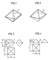
- Figs. 1 and 2 are perspective views of pieces which form part of the new game, and Figs. 3 and 4 are groups of dihedral projections of the pieces, indicating their relative dimensions;
- Figs. 5 and 6 show another two pieces which form part of the new game and Figs. 7 and 8 are groups of dihedral projections of the same pieces, indicating their relative dimensions;
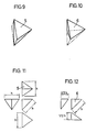
- Figs. 9 and 10 show another two pieces of the game described, and Figs. 11 and 12 are groups of dihedral projections of the same pieces indicating their relative dimensions;
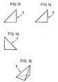
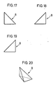
- Figs. 13 to 16 represent three dihedral projections and one perspective view respectively of a component having four triangular faces;
- Figs. 17 to 20 represent a component similar to the previous one which is a mirrored opposite thereof;
- Figs. 21 to 23 show the association of the components in the preceding figures in order to obtain a new element having four triangular faces;
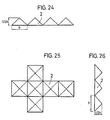
- Figs. 24, 25 and 26 are dihedral projections of a figure obtained by repeated association of pieces according to Fig. 2 and which has the shape of a Latin cross when viewed in plan;
- Fig. 27 shows the association of six pieces identical to that shown in Fig. 2, the juxtaposition of which gives rise to the cube shown in Fig. 28;
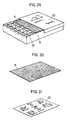
- Fig 29 shows a possible practical embodiment of the new game, constituted by a box which houses the pieces disposed in an arrangement which allows them to be grouped in the minimum of space, while Fig. 30 shows an additional component and Fig. 31 shows a play board for assembling the pieces, all of which can be included inside the box which houses and protects the pieces;
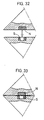
- Figs.32 and 33 represent a coupling of two components of the new game, achieved by respective magnetic elements inserted in faces corresponding to the two components;
- Figs. 34 and 35 likewise show the magnetic component of each piece, with the particular feature that in this case one of the magnetic elements is situated on a projection from one component while the other magnetic element is disposed in a recess in the other component;
- Figs. 36 and 37 show the coupling between two components, one of which has a recess while the other has a projection, recess and projection being of the same shape and size;
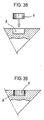
- Figs. 38 and 39 show one of the components of the new game carrying a regularly shaped recess in which it is possible optionally to fit a matching projection of the same shape and size;
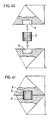
- Figs.40 and 41 show two phases in the operation of joining two components which can be fitted together, each of which has a recess of precsie shape, into each of which will be housed one half of a coupling member which, once coupling is completed, will remain simultaneously housed in the two contacting components.
-
Those elements in the drawings which are identified by numbers correspond to the parts referred to hereinafter.
-
The piece 1 shown in Fig. 1 is in the form of an octahedron or a right bipyramid of square main cross-section, the length of its minor axis being equal to the edge of the square main section, equivalent to two square pyramids joined at their bases, which side is equivalent to the height or distance between the vertices which define the vertical axis of symmetry.
-
The piece 2 shown in Fig. 2 consists of a right pyramid with a square base, the height of which is equivalent to one half of the side of the base, this figure being equivalent to one half of the preceding, if this is regarded as having been cut through a plane coincident with the maximum square of its plan according to Fig. 3 and which is the same, the piece in Fig. 1 being equivalent to two units of the piece in Fig. 2 which have been joined at their quadrangular bases.
-
The piece 3 in Fig. 5 is in practice equivalent to half the piece in Fig. 1, assumed to have been cut through a vertical plane passing through the axis of symmetry and through two vertices opposite the quadrangular bottom. In reality, it corresponds to a right pyramid with a rhombic base, of angles 70° 31' 44" and 109° 28' 16" along the side of the base √3/2 units and of a height √2/2 units.
-
The piece 4 in Fig. 6 is equivalent to one half of the piece in Fig. 2, sectioned through a vertical plane containing the axis of symmetry and two vertices opposite the square of the base, corresponding therefore to a right pyramid having as its base an isosceles triangle of dimensions (1,1, √2) units and having lateral faces formed by two triangles of dimensions 1, √3/2, √3/2) units and a triangle of dimensions √2, √3/2, √3/2) units.
-
The piece 5 in Figs. 9 and 11 is equivalent to half the piece 3 in Figs. 5 and 7 sectioned through a plane containing the vertical axis of symmetry and one of the vertices of the horizontal square bottom. In reality, it corresponds to a tetrahedron formed by two identical triangular faces of dimensions (1, √3/2 and √3/2) units.
-
The piece 6 in Figs. 10 and 12 is equivalent to one half of the piece 5 resulting from ideally cutting the latter through a horizontal plane containing two vertices of the horizontal bottom of the former and perpendicular to the vertical axis. It corresponds to a rectangular tetrahedron formed by three faces shaped as right-angled triangles respectively of dimensions (1, √2/2, √2/2), ( √2/2, √3/2, 1/2) and ( √2/2, √3/2, 1/2) units and an isosceles triangle of the dimensions (1, √3/2, √3/2) units.
-
The pieces 7 and 8 in Figs. 13 to 16 and 17 to 20 respectively correspond to the cross-section of the piece 6 through a plane passing through half of its face corresponding to the triangle having sides (1, √3/2, √3/2) and through the opposite edge. They correspond to respective bodies of four triangular faces each of which forms a right-angle, the pieces 7 and 8 being mirroed opposites of and symmetrical with each other in respect of the ideal cutting plane.
-
On a basis of the piece one and by successive decomposition into symmetrical modular sections, it is possible to arrive at the following relational diagram:
-
The shapes and sizes of the faces are reflected in the following Table:
-
Some elementary knowledge of descriptive geometry and the imagination of the player will make it possible to construct very different patterns and shapes based on the repeated or alternating use of the pieces in the game, and the assemblies illustrated in Figs. 24 to 28 will give some idea of possibilities.
-
If the pieces are connected by permanent magnets, these may be housed in the surfaces of the components as shown in Fig. 32 and 33, or they may be situated on projections T and in recesses U as shown in Figs. 34 and 35.
-
When the connection is made without magnets, projections V are provided which match recesses X as shown in Figs. 36 and 37.
-
According to another embodiment of the invention, the connection between components is effected by the disposition of recesses X on the faces of all the components, the pieces being coupled to one another directly or via the auxiliary elements Z which are shaped to match the shape of the recesses X while being of a height which is twice that of their depth, the auxiliary elements Y being of a height which is half that of the elements Z in order to mask the recesses X on the exposed faces of the components, all as illustrated in Figs. 38 and 41.
-
In Figs. 32 and 33, the elements of the new game are connected by the association of faces of the same shape and size which incorporate permanent magnets; those of one sign, for example N, are attracted by those which incorporate magnets of the opposite sign, in this case S, so producing stable connections which can be separated when required. It makes it possible to move the shapes formed as if they were one-piece bodies, and they can also be handled without any change in their geometrical shape so long as one of their parts is not intentionally moved in relation to the others. In this case, the magnetic elements N and S will remain flush-fitted in the respective surfaces of the faces in which they are installed. In the case of Figs. 34 and 35, one of the magnetic elements N is situated on the end face of a projection T which is in turn housed in a recess U of the same shape and size, made in the surface of the matching face of the other component.
-
In the case of Figs. 36 and 37, coupling between faces is achieved simply by inserting the nipples V emerging from one of the components into respective recesses X provided in the other component. Figs. 38 and 39 show the use of a complementary element Y shaped like a cylinder or a prism according to the shape of the recess X, while Figs. 40 and 41 show the use of a component Z, the height of which is equivalent to twice the depth of the recesses X in the components to be joined, the said element serving as a connecting member between the surfaces which are placed one against the other.
-
To house the components of the new game, it is advantageous to use a box 9 which is so dimensioned that it holds the various pieces which, in order to save space, will be arranged in the most suitable position in which they can be coupled, that is to say by taking advantage of their shape in order to form figures which occupy a minimum of space. The container is completed by a lid 10 and it likewise houses a board or sheet 4 of suitable design to serve as a base on which to form the patterns or shapes. The said sheet may have on its working surface a temporarily adhesive product to maintain cohesion of the shapes formed by association of the pieces.
-
The box 9 will also contain one or several sheets 12 carrying drawings which will show how to construct various shapes by using the pieces in the game, serving as an introduction to users of the game and providing them with inspiration for the construction of new shapes by their own initiative.
-
Any variations which do not affect, alter, change or modify the essence of the game described will be regarded as falling within the scope of this Patent.