EP0336922A1 - Elektromechanischer Antrieb für Stellglieder von Pumpedüsen - Google Patents
Elektromechanischer Antrieb für Stellglieder von Pumpedüsen Download PDFInfo
- Publication number
- EP0336922A1 EP0336922A1 EP89890086A EP89890086A EP0336922A1 EP 0336922 A1 EP0336922 A1 EP 0336922A1 EP 89890086 A EP89890086 A EP 89890086A EP 89890086 A EP89890086 A EP 89890086A EP 0336922 A1 EP0336922 A1 EP 0336922A1
- Authority
- EP
- European Patent Office
- Prior art keywords
- rotor
- drive according
- stator
- pole
- yoke
- Prior art date
- Legal status (The legal status is an assumption and is not a legal conclusion. Google has not performed a legal analysis and makes no representation as to the accuracy of the status listed.)
- Granted
Links
- 230000005284 excitation Effects 0.000 claims abstract description 17
- 238000002347 injection Methods 0.000 claims abstract description 9
- 239000007924 injection Substances 0.000 claims abstract description 9
- 239000000463 material Substances 0.000 claims abstract description 5
- 238000004804 winding Methods 0.000 claims description 8
- 230000005291 magnetic effect Effects 0.000 claims description 5
- 238000006073 displacement reaction Methods 0.000 claims description 3
- 239000007921 spray Substances 0.000 claims description 2
- 239000000696 magnetic material Substances 0.000 claims 2
- 238000010276 construction Methods 0.000 description 4
- 239000000446 fuel Substances 0.000 description 2
- 238000002485 combustion reaction Methods 0.000 description 1
- 230000008878 coupling Effects 0.000 description 1
- 238000010168 coupling process Methods 0.000 description 1
- 238000005859 coupling reaction Methods 0.000 description 1
- 239000003302 ferromagnetic material Substances 0.000 description 1
- 238000009434 installation Methods 0.000 description 1
- 238000009966 trimming Methods 0.000 description 1
- 238000009834 vaporization Methods 0.000 description 1
- 230000008016 vaporization Effects 0.000 description 1
Images


Classifications
-
- H—ELECTRICITY
- H01—ELECTRIC ELEMENTS
- H01F—MAGNETS; INDUCTANCES; TRANSFORMERS; SELECTION OF MATERIALS FOR THEIR MAGNETIC PROPERTIES
- H01F7/00—Magnets
- H01F7/06—Electromagnets; Actuators including electromagnets
- H01F7/08—Electromagnets; Actuators including electromagnets with armatures
- H01F7/14—Pivoting armatures
- H01F7/145—Rotary electromagnets with variable gap
-
- F—MECHANICAL ENGINEERING; LIGHTING; HEATING; WEAPONS; BLASTING
- F02—COMBUSTION ENGINES; HOT-GAS OR COMBUSTION-PRODUCT ENGINE PLANTS
- F02D—CONTROLLING COMBUSTION ENGINES
- F02D1/00—Controlling fuel-injection pumps, e.g. of high pressure injection type
- F02D1/02—Controlling fuel-injection pumps, e.g. of high pressure injection type not restricted to adjustment of injection timing, e.g. varying amount of fuel delivered
- F02D1/08—Transmission of control impulse to pump control, e.g. with power drive or power assistance
-
- F—MECHANICAL ENGINEERING; LIGHTING; HEATING; WEAPONS; BLASTING
- F02—COMBUSTION ENGINES; HOT-GAS OR COMBUSTION-PRODUCT ENGINE PLANTS
- F02M—SUPPLYING COMBUSTION ENGINES IN GENERAL WITH COMBUSTIBLE MIXTURES OR CONSTITUENTS THEREOF
- F02M57/00—Fuel-injectors combined or associated with other devices
- F02M57/02—Injectors structurally combined with fuel-injection pumps
-
- F—MECHANICAL ENGINEERING; LIGHTING; HEATING; WEAPONS; BLASTING
- F02—COMBUSTION ENGINES; HOT-GAS OR COMBUSTION-PRODUCT ENGINE PLANTS
- F02M—SUPPLYING COMBUSTION ENGINES IN GENERAL WITH COMBUSTIBLE MIXTURES OR CONSTITUENTS THEREOF
- F02M59/00—Pumps specially adapted for fuel-injection and not provided for in groups F02M39/00 -F02M57/00, e.g. rotary cylinder-block type of pumps
- F02M59/20—Varying fuel delivery in quantity or timing
- F02M59/24—Varying fuel delivery in quantity or timing with constant-length-stroke pistons having variable effective portion of stroke
- F02M59/243—Varying fuel delivery in quantity or timing with constant-length-stroke pistons having variable effective portion of stroke caused by movement of cylinders relative to their pistons
- F02M59/246—Mechanisms therefor
-
- F—MECHANICAL ENGINEERING; LIGHTING; HEATING; WEAPONS; BLASTING
- F02—COMBUSTION ENGINES; HOT-GAS OR COMBUSTION-PRODUCT ENGINE PLANTS
- F02M—SUPPLYING COMBUSTION ENGINES IN GENERAL WITH COMBUSTIBLE MIXTURES OR CONSTITUENTS THEREOF
- F02M59/00—Pumps specially adapted for fuel-injection and not provided for in groups F02M39/00 -F02M57/00, e.g. rotary cylinder-block type of pumps
- F02M59/20—Varying fuel delivery in quantity or timing
- F02M59/24—Varying fuel delivery in quantity or timing with constant-length-stroke pistons having variable effective portion of stroke
- F02M59/26—Varying fuel delivery in quantity or timing with constant-length-stroke pistons having variable effective portion of stroke caused by movements of pistons relative to their cylinders
- F02M59/28—Mechanisms therefor
-
- F—MECHANICAL ENGINEERING; LIGHTING; HEATING; WEAPONS; BLASTING
- F02—COMBUSTION ENGINES; HOT-GAS OR COMBUSTION-PRODUCT ENGINE PLANTS
- F02M—SUPPLYING COMBUSTION ENGINES IN GENERAL WITH COMBUSTIBLE MIXTURES OR CONSTITUENTS THEREOF
- F02M2200/00—Details of fuel-injection apparatus, not otherwise provided for
- F02M2200/24—Fuel-injection apparatus with sensors
Definitions
- the invention relates to an electromechanical drive for actuators of pump nozzles, in particular for the delivery quantity and / or spray start adjustment element.
- the aim of the invention is to provide an electromechanical drive which can be used in pump nozzles due to its compact dimensions and good efficiency with a simple and inexpensive construction.
- the drive according to the invention results in an extremely space-saving structure, which can be coaxial with respect to the rest of the structure of a pump nozzle, which results in a particularly simple mechanical coupling with the quantity actuator or the actuator for changing the injection timing. Further preferred embodiments are the subject of the subclaims.
- FIG. 1 shows an axial section through the upper part of a pump nozzle with a first embodiment of the drive according to the invention
- FIG. 2 shows a section along the line II-II of FIG. 1
- FIG. 3 shows a view corresponding to FIG. 2 a second Embodiment of the invention
- Fig. 4 and Fig. 5 in views corresponding to Fig. 1 and Fig. 2, a third embodiment of the invention, wherein Fig. 5 shows a section along the line VV of Fig. 4, Fig. 5a the development of one of the two pole pieces of the rotor of the third embodiment, FIGS. 6 and 7 in views corresponding to FIGS.
- FIG. 7 shows a section along the line VII-VII of FIG. 6
- FIG 8 shows a fifth embodiment of the invention in a view corresponding to FIG. 1
- FIG. 9 shows a top view of this embodiment, partly in section
- FIG. 10 shows an enlarged, partially sectioned partial view in the direction of arrow X in FIGS. 9 and F.
- 11 shows a sixth embodiment of the invention in an axial section through a pump nozzle.
- a pump nozzle 1 has a housing 2 and a spring-loaded piston 3, which can be actuated by means of a plunger 4 indicated by a broken line.
- the piston 3 is rotatably connected to a crank arm 5, from which a pin 6 protrudes upwards.
- the respective delivery rate can be adjusted by turning the crank arm 5 and thus the piston 3.
- the entire structure of such a pump nozzle, not shown here, in which a mechanical actuation of the crank arm is provided, for example by means of an adjusting rod, can be found, for example, in the already mentioned AT-PS 372 502.
- FIG. 1 and 2 also show an upper housing part 7 placed on the housing 2.
- an upwardly open, hollow pressure bolt 9, on which the tappet 4 engages passes.
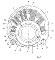
- An essentially hollow cylindrical rotor 10 of the electromechanical drive according to the invention which surrounds the pressure pin 9 concentrically, is mounted on the outer surface of the bush-like region of the upper housing part 7.
- This rotor is provided on its circumference with two hollow cylinder segment-like permanent magnets 11, 12 which are radially magnetized, which is indicated by the letters N and S.
- the magnets 11, 12 are diametrically opposite to each other with respect to the axis of rotation a and each extend over an angle of e.g. 120 °.
- the rotor 10 is provided with an axially parallel outer groove 13, in which the pin 6 of the crank arm 5 engages, so that the rotor 10 is connected to the crank arm 5 and thus to the piston 3 for rotation.
- the pin 6 is axially displaceably mounted in the outer groove 13 so that it can move in accordance with the piston stroke.
- the rotor 10 is also spring-loaded in one direction of rotation by means of a torsion spring 14.
- One end 14a of this torsion spring 14 is anchored to the upper housing part 7, the other end 14b to the rotor 10.
- a rotor 15 is associated with a stator 15, which has a yoke 15a made of a semicircular laminated core 15a and which has two pole shoes 16, 17 which, while leaving an air gap, are assigned to rotor 10 or its two permanent magnets 11, 12.
- the stator 15 is provided with an excitation coil 18, the windings of which have axially parallel sections 19 in grooves (not shown here) on the inside of the pole shoes 16, 17.
- the coil 18 is hiebei so wound that at a certain current flow Current at sections 19 of one pole piece 16 emerges from the drawing plane of FIG. 2 when it enters the drawing plane at sections of the opposite pole piece 17.
- the remaining winding sections of the coil 18 are guided asymmetrically to one side (to the right in the drawing), which also results in a corresponding construction of the upper housing part 7, which is due to the restricted space, in particular to the position of the camshaft, which is to the left in the drawing the pump nozzle would be, considerate.
- the drive according to the invention has a space-saving structure and can be used with pump nozzles without these having to be significantly modified.
- the proportionality between the actuation angle and the excitation current is given with good linearity over the entire adjustment range — approximately 120 ° in the exemplary embodiment described.
- FIG. 3 A further exemplary embodiment in which the limited space is also taken into account is shown in FIG. 3.
- the structure of the pump nozzle 1 as such and that of the rotor 10 essentially corresponds to that according to FIGS. 1 and 2 and therefore requires no further explanation.
- the pin 6 of the crank arm 5 is held in a driving eye 20 of the rotor 10 here.
- the stator 21 consists of a closed yoke 22 which completely encompasses the rotor 10 and is made of magnetically soft, ferromagnetic material.
- Six cores 23a to f protrude inward from the yoke 22. Each of these cores is provided with a pole piece 24a to f at its end. The pole shoes 24 adjoin one another without significant gaps and cover a rotor area of almost 180 °.
- Each of the cores 23 is wound with an excitation winding 25a to f, all windings being connected in series. Depending on the impedance conditions, a parallel connection or series-parallel connection of the six excitation windings 25 is of course also conceivable.
- the stator 21, the left half of which is shown in section in the drawing, is constructed symmetrically with respect to a central plane e. There is still enough space between the windings 25b-25c-25d-25e for three fastening bolts 26 or the like. which ensure the connection of the stator 21 or an upper part of the housing (not shown here) to the lower part of the pump nozzle or the mounting of the stator 21.
- the same purpose is also served by two fastening bolts 27 or the like which penetrate the half-bores of the yoke 22. All or some of the bolts mentioned can also be used to fasten the pump nozzle in the cylinder head or on the camshaft housing.
- the six pole pieces 24a to f can be regarded as the only pole piece of a specific polarity corresponding to the current flow, to which a second pole piece 28 of opposite polarity is located, which also extends over almost 180 °.
- the excitation windings are essentially on one side of the pump nozzle 1, so that there is enough space on the opposite side for the camshaft of the motor. With good linearity, an adjustment angle of 90 to 110 ° can be achieved, which corresponds to the usual adjustment angle of crank arm 5.
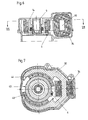
- FIGS. 4, 5 and 5a The embodiment of the drive according to the invention shown in FIGS. 4, 5 and 5a has a stator 30 comprising the fork 29 in the manner of a fork with two opposing pole shoes 31, 32.
- a stator 30 comprising the fork 29 in the manner of a fork with two opposing pole shoes 31, 32.
- an excitation coil 34 is seated on the web part 33 of the approximately U-shaped stator, e.g. is designed as a laminated core.
- the rotor 29 surrounds the pressure pin 9, which is provided at its lower end with a support plate 35 for a pressure spring 36, as corresponds to the prior art (cf. the already mentioned AT-PS 372 502).
- the rotor 29 is not provided with permanent magnets, but has two diametrically opposed rotor pole shoes 37, 38.
- a working air gap 39 remains between the outer surfaces of the rotor pole shoes 37, 38 and the inner surfaces of the stator pole shoes 31, 32 the rotor body outwardly projecting pole shoes 37, 38 are each on one side with a straight, ie bounded in an axial plane of the rotor 29 flat side surface 40, whereas the corresponding boundary surfaces 41 on the other side (seen in the circumferential direction) of the pole shoes 37, 38 slope down from top to bottom.
- the development of the cylindrically curved outer surface of a rotor pole shoe is illustrated in Fig. 5a.
- a rotor pole piece extends over an angle of approximately 90 ° and the sloping boundary surface 41 extends over an angle of approximately 30 ° from the upper end face of the rotor to its lower end face.
- the rotor 29, which is likewise loaded with a torsion spring 14, is shown in FIG. 5 in its position which corresponds to the maximum rotation, ie the maximum operating current through the excitation coil 34.
- the overlap area between the stator pole shoes 31, 32 and the rotor pole shoes 37, 38 takes on as a function of the angle of rotation , this dependence being a function of the slope of the boundary surface 41.
- the magnetic resistance of the present magnetic circuit changes with the angle of rotation and it can be shown that the angle of rotation of the rotor 29 loaded with the spring torque of the spring 14 can be changed by changing the current through the excitation coil 34, for example over an angle of rotation of 90 ° a largely linear dependence of the twist angle on the current strength can be achieved.
- the pin 6 of the crank arm is held axially displaceably and rotatably in a bore 42 of the rotor 29.
- FIGS. 6 and 7 corresponds essentially to the configuration explained with reference to FIGS. 4 and 5 with respect to the stator structure, whereas the rotor 43 in turn corresponds to the rotor according to the embodiments of FIGS. 1 to 3, ie two radial magnetized, hollow cylinder segment-like permanent magnets 44, 45 carries on its circumference.
- the function also corresponds to that described at the beginning. 4 to 7 entirely on one side of the drive has the advantage that the upper part of the pump nozzle on the side opposite the excitation coil 34 can be brought close to the drive camshaft.
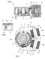
- stator 46 of which is characterized by a particularly compact and mechanically stable structure.
- the stator 46 which consists of a laminated core, completely encompasses the rotor 47, the excitation coil 48 consisting of two mechanically separate halves 48a, 48b which are seated on two web regions 49, 50 of the stator 46 which are inclined at an obtuse angle.
- the coil halves 48a, 48b thus so to speak nestle against the rotor 47, which results in the compact structure.
- an additional web 146 is provided between the web regions 49, 50 carrying the coil halves 48a, 48b, which magnetically represents a shunt.
- the web 146 is designed with a large cross-sectional constriction 246, in the area of which the material of the stator 46 already saturates at the operating field strengths.
- Another constriction 346 of this type is provided on the stator 46 opposite the excitation coil 48.
- the sheets of the stator 46 are alternately overlapped in the corner areas 446 shown in dotted lines, so that a simple pushing of the coil halves 48a, 48b onto the web areas 49, 50 is possible during assembly.
- the rotor 47 is similar to the rotor 43 of the embodiment according to FIGS. 6 and 7, but here a resistance sensor is provided for the feedback of the angle of rotation of the rotor 43.
- a resistance sensor is provided for the feedback of the angle of rotation of the rotor 43.
- a grinder 55 with two resilient wiper arms 56, 57, which are electrically connected to one another or are formed in one piece, is assigned to these resistance tracks and is attached to the rotor 47, for example by means of a clamping screw 58 (FIG. 10).
- the wiper arms 56, 57 rest resiliently on the resistance tracks 52, 53.
- the ends of the resistor tracks 52, 53 which are not connected to one another, can each be connected to a voltage source via a film-like trimming resistor (not shown) provided on the upper side of the insulating carrier, so that the voltage on the grinder 55 is a measure of the angle of rotation of the Represents rotor 47.
- a flexible electrical connection line (not shown) for the grinder 55 must be led through the housing of the drive to the outside.
- An opening 59 can be provided in the housing cover 51, which is opposite the adjustment resistors already mentioned. Through this opening, a change in the adjustment resistances, ie an adjustment of the transmitter to the respective pump nozzle, is possible by means of vaporization by means of a laser. It is understood that feedback of the angle of rotation can in principle also take place with a single resistance track and a wiper arm.
- the sensor shown can be used in the same way in the other embodiments of the invention described here.
- FIG. 11 An embodiment is described in FIG. 11, each of which has a drive for the quantity actuator or for adjusting the start of injection.
- a rotor 60 is also present here, to which a stator 61 is assigned.
- the pin 6 of the crank arm 5 engages on the rotor 60.
- a second drive 6 which has a rotor 62 and a stator 63. Both drives can be designed according to one of the constructions described above, but a helical groove 64 is formed in the jacket of the rotor 62, in which the hook-like part 65 of a separating sleeve 66 engages, which in turn is connected to a control sleeve 67.
- a rotation of the rotor 62 causes an axial displacement of the hook-like part 65 engaging in the groove 64 and ultimately an axial displacement of the control sleeve 67.
- the excitation coil 68 of the second drive can be controlled via a schematically shown electronic control device 69.
Landscapes
- Engineering & Computer Science (AREA)
- Chemical & Material Sciences (AREA)
- Combustion & Propulsion (AREA)
- Mechanical Engineering (AREA)
- General Engineering & Computer Science (AREA)
- Physics & Mathematics (AREA)
- Electromagnetism (AREA)
- Power Engineering (AREA)
- Fuel-Injection Apparatus (AREA)
- Details Or Accessories Of Spraying Plant Or Apparatus (AREA)
- Lubrication Of Internal Combustion Engines (AREA)
- General Electrical Machinery Utilizing Piezoelectricity, Electrostriction Or Magnetostriction (AREA)
Abstract
Description
- Die Erfindung bezieht sich auf einen elektromechanischen Antrieb für Stellglieder von Pumpedüsen, insbesondere für das Fördermengen -und/oder Spritzbeginnverstellglied.
- Bei Pumpedüsen für Brennkraftmaschinen ist es üblich, das Mengenstellwerk mechanisch, z.B. über ein Gestänge, Nocken etc. zu verstellen. Der Einsatz elektronischer Regler für die Kraftstoffeinspritzung hat zur Einführung elektromechanischer Antriebe für die Mengenstellglieder geführt. Ein derartiger Antrieb für das Mengenstellglied einer Kraftstoffeinspritzpumpe ist beispielsweise in der DE-OS 28 45 139 beschrieben. Hiebei wird ein auf einer Welle sitzender, in einer Drehrichtung federbelasteter Drehanker entsprechend dem Feld einer Erregerspule verdreht, wodurch über die Welle und eine Mitnahmekurbel ein Ringschieber verstellt wird.
- Die bekannte Konstruktion benötigt jedoch viel Platz und ist daher im Zusammenhang mit Pumpedüsen, die für jeden Zylinder eines Motors vorgesehen sind und die z.B. in der AT-PS 372 502 beschrieben sind, kaum verwendbar. Da neben den in den Zylinderkopf eingesetzten Pumpedüsen üblicherweise die Nockenwelle für die Betätigung der Ventile und der Kolben der Pumpedüsen verläuft, wobei meist Kipphebel zwischengeschaltet sind, steht auch wenig Bauraum zur Verfügung.
- Ziel der Erfindung ist die Schaffung eines elektromechanischen Antriebs, der auf Grund kompakter Abmessungen und eines guten Wirkungsgrades bei einfachem und billigem Aufbau bei Pumpedüsen Anwendung finden kann.
- Dieses Ziel läßt sich mit einem Antrieb entsprechend Patentanspruch 1 erreichen.
- Der Antrieb nach der Erfindung ergibt einen überaus raumsparenden Aufbau, der bezüglich des übrigen Aufbaues einer Pumpedüse koaxial liegen kann, wodurch sich eine besonders einfache mechanische Kupplung mit dem Mengenstellglied oder dem Stellglied für die Änderung des Einspritzzeitpunktes ergibt. Weitere bevorzugte Ausbildungen sind Gegenstand der Unteransprüche.
- Die Erfindung samt ihren weiteren Vorteilen ist im folgenden an Hand zweier Ausführungsbeispiele näher erläutert, die in der Zeichnung veranschaulicht sind. In dieser zeigen Fig. 1 einen Axialschnitt durch den oberen Teil einer Pumpedüse mit einer ersten Ausführungsform des erfindungsgemäßen Antriebes, Fig. 2 einen Schnitt nach der Linie II-II der Fig. 1, Fig. 3 in einer Ansicht entsprechend Fig. 2 eine zweite Ausführungsform der Erfindung, Fig. 4 und Fig. 5 in Ansichten entsprechend Fig. 1 und Fig. 2 eine dritte Ausführungsform der Erfindung, wobei Fig. 5 einen Schnitt nach der Linie V-V der Fig. 4 darstellt, Fig. 5a die Abwicklung eines der beiden Polschuhe des Rotors der dritten Ausführungsform, Fig. 6 und Fig. 7 in Ansichten entsprechend Fig. 1 und Fig. 2 eine vierte Ausführungsform der Erfindung, wobei Fig. 7 einen Schnitt nach der Linie VII-VII der Fig. 6 darstellt, Fig. 8 eine fünfte Ausführungsform der Erfindung in einer Ansicht entsprechend Fig. 1, Fig. 9 eine Draufsicht auf diese Ausführungsform, teilweise geschnitten und Fig. 10 eine vergrößerte, teilweise geschnittene Teilansicht in Richtung des Pfeiles X der Fig. 9 und Fig. 11 eine sechste Ausführungsform der Erfindung in einem Axialschnitt durch eine Pumpedüse.
- Gemäß Fig. 1 und 2 besitzt eine Pumpedüse 1 ein Gehäuse 2 und einen federbelasteten Kolben 3, der mittels eines strichliert angedeuteten Stößels 4 betätigt werden kann. Der Kolben 3 ist drehfest mit einem Kurbelarm 5 verbunden, von dem ein Stift 6 nach oben absteht. Durch Verdrehen des Kurbelarmes 5 und damit des Kolbens 3 kann die jeweilige Fördermenge eingestellt werden. Der gesamte, hier nicht näher gezeigte Aufbau einer solchen Pumpedüse, bei der eine mechanische Betätigung des Kurbelarms, etwa mittels einer Verstellstange, vorgesehen ist, kann z.B. der bereits erwähnten AT-PS 372 502 entnommen werden.
- Den Fig. 1 und 2 ist weiters ein auf das Gehäuse 2 aufgesetzter Gehäuseoberteil 7 zu entnehmen. Durch einen buchsenartigen Bereich des Gehäuseoberteils 7 tritt, mittels einer Runddichtung 8 abgedichtet, ein nach oben hin offener, hohler Druckbolzen 9, an dem der Stößel 4 angreift. An der Außenfläche des buchsenartigen Bereichs des Gehäuseoberteils 7 ist ein im wesentlichen hohlzylindrischer Rotor 10 des erfindungsgemäßen elektromechanischen Antriebes gelagert, der den Druckbolzen 9 konzentrisch umgibt. Dieser Rotor ist an seinem Umfang mit zwei hohlzylindersegmentartigen Dauermagneten 11, 12 versehen, die radial magnetisiert sind, was durch die Buchstaben N und S angedeutet ist. Die Magnete 11, 12 liegen einander diametral bezüglich der Drehachse a gegenüber und erstrecken sich je über einen Winkel von z.B. 120°.
- Der Rotor 10 ist mit einer achsparallelen Außennut 13 versehen, in die der Stift 6 des Kurbelarms 5 eingreift, sodaß der Rotor 10 mit dem Kurbelarm 5 und somit mit dem Kolben 3 auf Drehung verbunden ist. Der Stift 6 ist jedoch in der Außennut 13 axial verschieblich gelagert, sodaß er sich dem Kolbenhub entsprechend verschieben kann. Der Rotor 10 ist ferner mit Hilfe einer Drehfeder 14 in einer Drehrichtung federbelastet. Ein Ende 14a dieser Drehfeder 14 ist an dem Gehäuseoberteil 7, das andere Ende 14b an dem Rotor 10 verankert.
- Dem Rotor 10 ist ein Stator 15 zugeordnet, der ein Joch 15a aus einem halbkreisförmigen Blechpaket 15a aufweist und der zwei Polschuhe 16, 17 besitzt, die unter Belassung eines Luftspaltes dem Rotor 10 bzw. dessen beiden Dauermagneten 11, 12 zugeordnet sind. Der Stator 15 ist mit einer Erregerspule 18 versehen, deren Windungen in hier nicht näher ersichtlichen Nuten an der Innenseite der Polschuhe 16, 17 achsparallele Abschnitte 19 aufweisen. Die Spule 18 ist hiebei so gewickelt, daß bei einem bestimmten Stromfluß der Strom bei Abschnitten 19 des einen Polschuhes 16 aus der Zeichenebene der Fig. 2 austritt, wenn er bei den Abschnitten des gegenüberliegenden Polschuhes 17 in die Zeichenebene eintritt. Die restlichen Wicklungsabschnitte der Spule 18 sind asymmetrisch nach einer Seite geführt (in der Zeichnung nach rechts), wodurch sich auch ein entsprechender Aufbau des Gehäuseoberteils 7 ergibt, der auf die beengten Platzverhältnisse, insbesondere auf die Lage der Nockenwelle, die in der Zeichnung links von der Pumpedüse läge, Rücksicht nimmt.
- Fließt durch die Spule 18 Gleichstrom, so treten im Bereich der Nuten bzw. der Spulenabschnitte 18 gleichgerichtete Umfangskräfte auf, die eine Verdrehung des Rotors 10 gegen die Vorspannung der Feder 14 bewirken. Wegen der Federbelastung ergibt sich ein dem Spulenstrom proportionaler Verdrehungswinkel des Rotors 10 und damit auch des Pumpenkolbens 3, so daß über den Strom durch die Erregerspule die Einspritzmenge der Pumpedüse 1 eingestellt werden kann.
- Wie ersichtlich, besitzt der erfindungsgemäße Antrieb einen raumsparenden Aufbau und ist bei Pumpedüsen anwendbar, ohne daß diese wesentlich modifiziert werden müssen. Die Proportionalität zwischen Stellwinkel und Erregerstrom ist über den gesamten Verstellbereich - bei dem beschriebenen Ausführungsbeispiel etwa 120° - mit guter Linearität gegeben.
- Ein weiteres Ausführungsbeispiel bei dem gleichfalls den beschränkten Platzverhältnissen Rechnung getragen wird, geht aus Fig. 3 hervor. Der Aufbau der Pumpedüse 1 als solcher sowie der des Rotors 10 entspricht im wesentlichen jenem nach Fig. 1 und 2 und bedarf daher keiner weiteren Erläuterung. Der Stift 6 des Kurbelarms 5 ist hier jedoch in einem Mitnehmerauge 20 des Rotors 10 gehalten.
- Der Stator 21 besteht aus einem geschlossenen, den Rotor 10 völlig umfassenden Joch 22 aus magnetisch weichem, ferromagnetischen Material. Von dem Joch 22 stehen sechs Kerne 23a bis f nach innen ab. Jeder dieser Kerne ist an seinem Ende mit einem Polschuh 24a bis f versehen. Die Polschuhe 24 schließen ohne wesentliche Zwischenräume aneinander an und bedecken hiebei einen Rotorbereich von fast 180°. Jeder der Kerne 23 ist mit einer Erregerwicklung 25a bis f bewickelt, wobei sämtliche Wicklungen in Serie geschaltet sind. Je nach Impedanzverhältnissen ist natürlich auch eine Parallelschaltung oder Serien-Parallelschaltung der sechs Erregerwicklungen 25 denkbar.
- Wie ersichtlich ist der Stator 21, dessen linke Hälfte in der Zeichnung geschnitten dargestellt ist, bezüglich einer Mittelebene e symmetrisch aufgebaut. Zwischen den Wicklungen 25b-25c-25d-25e bleibt noch genügend Zwischenraum für drei Befestigungsbolzen 26 od.dgl. die für die Verbindung des Stators 21 bzw. eines hier nicht ersichtlichen Gehäuseoberteiles mit dem unteren Teil der Pumpedüse bzw. für die Halterung des Stators 21 sorgen. Demselben Zweck dienen auch zwei Befestigungsbolzen 27 od.dgl., die Halbbohrungen des Joches 22 durchsetzen. Alle oder einige der genannten Bolzen können auch zur Befestigung der Pumpedüse im Zylinderkopf bzw. an dem Nockenwellengehäuse herangezogen werden.
- Von der magnetischen Wirkung gesehen können die sechs Polschuhe 24a bis f als einziger Polschuh einer dem Stromfluß entsprechenden bestimmten Polarität aufgefaßt werden, dem ein zweiter Polschuh 28 entgegengesetzter Polarität gegenüberliegt, der sich gleichfalls über fast 180° erstreckt.
- Auch bei dieser Ausführungsform liegen die Erregerwicklungen im wesentlichen an einer Seite der Pumpedüse 1, sodaß an der gegenüberliegenden Seite genügend Raum für die Hockenwelle des Motors verbleibt. Bei guter Linearität ist ein Stellwinkel von 90 bis 110° erreichbar, was dem üblichen Stellwinkel des Kurbelarms 5 entspricht.
- Die in den Fig. 4, 5, und 5a dargestellte Ausführungsform des erfindungsgemäßen Antriebes besitzt einen den Rotor 29 gabelartig umfassenden Stator 30 mit zwei einander gegenüberliegenden Polschuhen 31, 32. Am Stegteil 33 des annähernd u-förmigen Stators, der z.B. als Blechpaket ausgeführt ist, sitzt eine Erregerspule 34.
- Auch hier umgibt der Rotor 29 den Druckbolzen 9, der an seinem unteren Ende mit einem Abstützteller 35 für eine Druckfeder 36 versehen ist, wie es dem Stand der Technik entspricht (vgl. die bereits erwähnte AT-PS 372 502). Der Rotor 29 ist jedoch im Gegensatz zu den vorgehend beschriebenen Beispielen nicht mit Dauermagneten versehen, sondern besitzt zwei diametral gegenüberliegende Rotorpolschuhe 37, 38. Zwischen den Außenflächen der Rotorpolschuhe 37, 38 und den Innenflächen der Statorpolschuhe 31, 32 verbleibt ein Arbeitsluftspalt 39. Die von dem Rotorkörper nach außen abstehenden Polschuhe 37, 38 sind je an einer Seite mit einer geraden, d.h. in einer Axialebene des Rotors 29 liegenden ebenen Seitenfläche 40 begrenzt, wogegen die entsprechenden Begrenzungsflächen 41 an der anderen Seite (in Umfangsrichtung gesehen) der Polschuhe 37, 38 von oben nach unten abfallend verläuft. Die Abwicklung der zylindrisch gekrümmten Außenfläche eines Rotorpolschuhes ist in Fig. 5a veranschaulicht. Bei dem gegenständlichen Beispiel erstreckt sich ein Rotorpolschuh über einen Winkel von etwa 90° und die abfallende Begrenzungsfläche 41 verläuft über einen Winkel von etwa 30° von der oberen Stirnfläche des Rotors bis zu dessen unterer Stirnfläche.
- Der Rotor 29, der gleichfalls mit einer Drehfeder 14 belastet ist, ist in Fig. 5 in seiner Stellung gezeigt, die der maximalen Verdrehung, d.h. dem maximalen Betriebsstrom durch die Erregerspule 34 entspricht. Bei einer Verdrehung aus dieser Lage heraus, in Fig. 5 im Uhrzeigersinn, nimmt die Überdeckungsfläche zwischen den Statorpolschuhen 31, 32 und den Rotorpolschuhen 37, 38 in Abhängigkeit von dem Drehwinkel ab, wobei diese Abhängigkeit eine Funktion der Steigung der Begrenzungsfläche 41 ist. Somit ändert sich mit dem Drehwinkel der magnetische Widerstand des vorliegenden Magnetkreises und es läßt sich zeigen, daß sich der Drehwinkel des mit dem Federdrehmoment der Feder 14 belasteten Rotors 29 durch Änderung des Stromes durch die Erregerspule 34 ändern läßt, wobei z.B. über einen Drehwinkel von 90° eine weitgehend lineare Abhängigkeit des Verdrehungswinkels von der Stromstärke erzielbar ist.
- Bei dieser Ausführungsform, die ohne Permanentmagnete das Auslangen findet, ist der Stift 6 des Kurbelarmes in einer Bohrung 42 des Rotors 29 axial verschieblich und drehbar gehalten.
- Die in den Fig. 6 und 7 veranschaulichte weitere Ausführungsform entspricht bezüglich des Statoraufbaues im wesentlichen der an Hand der Fig. 4 und 5 erläuterten Ausbildung, wogegen der Rotor 43 wiederum dem Rotor nach den Ausführungsformen der Fig. 1 bis 3 entspricht, d.h., zwei radiale magnetisierte, hohlzylindersegmentartige Dauermagnete 44, 45 an seinem Umfang trägt. Auch die Funktion entspricht der eingangs beschriebenen. Die Verlagerung der Erregerspule 34 bei den Ausführungen nach Fig. 4 bis 7 gänzlich an eine Seite des Antriebes bietet in manchen Fällen den Vorteil, daß der Oberteil der Pumpedüse an der der Erregerspule 34 gegenüberliegenden Seite nahe an die Antriebsnockenwelle herangebracht werden kann.
- Fig. 8 und 9 zeigen eine Ausführungsform, deren Stator 46 sich durch einen besonders kompakten und mechanisch stabilen Aufbau auszeichnet. Der Stator 46, der aus einem Blechpaket besteht, umfaßt den Rotor 47 vollständig, wobei die Erregerspule 48 aus zwei mechanisch getrennten Hälften 48a, 48b besteht, die auf zwei unter einem stumpfen Winkel gegeneinander geneigten Stegbereichen 49, 50 des Stators 46 sitzen.
- Die Spulenhälften 48a, 48b schmiegen sich somit gewissermaßen an den Rotor 47 an, woraus der kompakte Aufbau resultiert. Zur Verbesserung der mechanischen Stabilität ist zwischen den die Spulenhälften 48a, 48b tragenden Stegbereichen 49, 50 ein zusätzlicher Steg 146 vorgesehen, der magnetisch einen Nebenschluß darstellt. Um diesem unerwünschten Nebenschluß entgegenzuwirken, ist der Steg 146 mit einer starken Querschnittsverengung 246 ausgebildet, in deren Bereich das Material des Stators 46 bereits bei den Betriebsfeldstärken in der Sättigung liegt. Eine weitere Verengung 346 dieser Art ist an dem Stator 46 gegenüber der Erregerspule 48 vorgesehen. Die Bleche des Stators 46 sind in den punktiert gezeigten Eckbereichen 446 abwechselnd überlappt zusammengefügt, sodaß bei der Montage ein einfaches Aufschieben der Spulenhälften 48a, 48b auf die Stegbereiche 49, 50 möglich ist.
- Der Rotor 47 gleicht dem Rotor 43 der Ausführung nach Fig. 6 und 7, doch ist hier ein Widerstandsgeber für die Rückmeldung des Verdrehungswinkels des Rotors 43 vorgesehen. An der Unterseite des oberen Gehäusedeckels 51 des Antriebes bzw. der Pumpedüse sind zwei an ihren einen Enden elektrisch miteinander verbundene kreisbogenförmige Widerstandsbahnen 52, 53 auf einem isolierenden Träger 54 vorgesehen. Diesen Widerstandsbahnen ist ein Schleifer 55 mit zwei elektrisch miteinander verbundenen bzw. einstückig ausgebildeten federnden Schleiferarmen 56, 57 zugeordnet, der an dem Rotor 47 befestigt ist, z.B. mittels einer Klemmschraube 58 (Fig. 10). Bei aufgesetztem Gehäusedeckel 51 liegen die Schleiferarme 56, 57 federnd an den Widerstandsbahnen 52, 53 an. Die nicht miteinander verbundenen Enden der Widerstandsbahnen 52, 53 können je über einen an der Oberseite des isolierenden Trägers vorgesehenen filmartigen Abgleichwiderstandes (nicht gezeigt) an eine Spannungsquelle angeschlossen sein, sodaß die Spannung am Schleifer 55 ein Maß für den Verdrehungswinkel des Rotors 47 darstellt. Selbstverständlich muß für den Schleifer 55 eine flexible elektrische Anschlußleitung (nicht gezeigt) durch das Gehäuse des Antriebes nach außen geführt sein. In dem Gehäusedeckel 51 kann eine Öffnung 59 vorgesehen sein, die den bereits erwähnten Abgleichwiderständen gegenüberliegt. Durch diese Öffnung hindurch ist durch Wegdampfen mittels eines Lasers eine Änderung der Abgleichwiderstände, d.h. ein Justieren des Gebers an die jeweilige Pumpedüse möglich. Es versteht sich, daß auch mit einer einzigen Widerstandsbahn und einem Schleiferarm prinzipiell eine Rückmeldung des Drehwinkels erfolgen kann. Der gezeigte Geber kann in gleicher Weise bei den anderen, hier beschriebenen Ausführungsformen der Erfindung zur Anwendung kommen.
- In Fig. 11 ist eine Ausführungsform beschrieben, die je einen Antrieb für das Mengenstellglied bzw. für die Verstellung des Einspritzbeginns besitzt. Wie bei den zuvor beschriebenen Ausführungsformen liegt auch hier ein Rotor 60 vor, dem ein Stator 61 zugeordnet ist. An dem Rotor 60 greift der Stift 6 des Kurbelarmes 5 an.
- Unterhalb dieses ersten Antriebes ist ein zweiter Antrieb 6 vorgesehen, der einen Rotor 62 und einen Stator 63 besitzt. Beide Antriebe können entsprechend einer der zuvor beschriebenen Konstruktionen ausgebildet sein, doch ist in dem Mantel des Rotors 62 eine schraubenförmige Nut 64 ausgebildet, in die der hakenartige Teil 65 einer Trennhülse 66 eingreift, welche ihrerseits mit einer Steuerhülse 67 verbunden ist.
- Es sei an dieser Stelle angemerkt, daß die axiale Verstellbarkeit der Steuerhülse zum Zwecke der Veränderung des Einspritzbeginns beispielsweise aus der DE-A1-31 43 073 bekannt geworden ist, doch erfolgt dort die Verstellung der Steuerhülse unmittelbar durch einen Hydraulikkolben.
- Zurückkommend auf die Ausführung nach Fig. 11 erkennt man, daß ein Verdrehen des Rotors 62 eine axiale Verschiebung des in die Nut 64 eingreifenden hakenartigen Teils 65 und letztlich eine axiale Verschiebung der Steuerhülse 67 bewirkt. Die Erregerspule 68 des zweiten Antriebes kann über ein schematisch gezeigtes, elektronisches Steuergerät 69 angesteuert werden.
Claims (10)
Priority Applications (1)
| Application Number | Priority Date | Filing Date | Title |
|---|---|---|---|
| AT89890086T ATE65113T1 (de) | 1988-04-08 | 1989-03-29 | Elektromechanischer antrieb fuer stellglieder von pumpeduesen. |
Applications Claiming Priority (2)
| Application Number | Priority Date | Filing Date | Title |
|---|---|---|---|
| DE3811844A DE3811844C1 (de) | 1988-04-08 | 1988-04-08 | |
| DE3811844 | 1988-04-08 |
Publications (2)
| Publication Number | Publication Date |
|---|---|
| EP0336922A1 true EP0336922A1 (de) | 1989-10-11 |
| EP0336922B1 EP0336922B1 (de) | 1991-07-10 |
Family
ID=6351640
Family Applications (1)
| Application Number | Title | Priority Date | Filing Date |
|---|---|---|---|
| EP89890086A Expired - Lifetime EP0336922B1 (de) | 1988-04-08 | 1989-03-29 | Elektromechanischer Antrieb für Stellglieder von Pumpedüsen |
Country Status (4)
| Country | Link |
|---|---|
| EP (1) | EP0336922B1 (de) |
| AT (1) | ATE65113T1 (de) |
| DE (2) | DE3811844C1 (de) |
| ES (1) | ES2024073B3 (de) |
Cited By (1)
| Publication number | Priority date | Publication date | Assignee | Title |
|---|---|---|---|---|
| CN106053713A (zh) * | 2016-07-12 | 2016-10-26 | 上海化工研究院 | 一种用于气雾剂性能检测过程的电控定量释放装置 |
Families Citing this family (1)
| Publication number | Priority date | Publication date | Assignee | Title |
|---|---|---|---|---|
| DE19859622A1 (de) | 1998-12-23 | 2000-07-06 | Braun Gmbh | Antriebseinrichtung für oszillierende elektrische Produkte des persönlichen Bedarfs, insbesondere Trockenrasierer |
Citations (2)
| Publication number | Priority date | Publication date | Assignee | Title |
|---|---|---|---|---|
| EP0164333A1 (de) * | 1984-04-30 | 1985-12-11 | VOEST-ALPINE-Friedmann Gesellschaft m.b.H. | Einspritzpumpe für Brennkraftmaschinen |
| GB2189846A (en) * | 1986-04-28 | 1987-11-04 | Diesel Kiki Co | Fuel injection pump |
Family Cites Families (3)
| Publication number | Priority date | Publication date | Assignee | Title |
|---|---|---|---|---|
| DE2845139A1 (de) * | 1978-10-17 | 1980-04-30 | Bosch Gmbh Robert | Regeleinrichtung fuer eine kraftstoffeinspritzpumpe |
| AT372502B (de) * | 1981-02-02 | 1983-10-25 | Friedmann & Maier Ag | Kraftstoffeinspritzpumpe fuer brennkraftmaschinen, insbesondere dieselmotoren |
| DE3337590A1 (de) * | 1983-10-15 | 1985-04-25 | Robert Bosch Gmbh, 7000 Stuttgart | Elektrischer stellmotor |
-
1988
- 1988-04-08 DE DE3811844A patent/DE3811844C1/de not_active Expired
-
1989
- 1989-03-29 ES ES89890086T patent/ES2024073B3/es not_active Expired - Lifetime
- 1989-03-29 AT AT89890086T patent/ATE65113T1/de not_active IP Right Cessation
- 1989-03-29 DE DE8989890086T patent/DE58900162D1/de not_active Expired - Fee Related
- 1989-03-29 EP EP89890086A patent/EP0336922B1/de not_active Expired - Lifetime
Patent Citations (2)
| Publication number | Priority date | Publication date | Assignee | Title |
|---|---|---|---|---|
| EP0164333A1 (de) * | 1984-04-30 | 1985-12-11 | VOEST-ALPINE-Friedmann Gesellschaft m.b.H. | Einspritzpumpe für Brennkraftmaschinen |
| GB2189846A (en) * | 1986-04-28 | 1987-11-04 | Diesel Kiki Co | Fuel injection pump |
Non-Patent Citations (2)
| Title |
|---|
| PATENT ABSTRACTS OF JAPAN vol. 11, no. 82 (M-571)(2529) 12 März 1987, & JP-A-61 237880 (YANMAR DIESEL ENGINE CO LTD) 23 Oktober 1986, * |
| PATENT ABSTRACTS OF JAPAN vol. 8, no. 210 (M-328)(1647) 26 September 1984, & JP-A-59 99063 (HINO JIDOSHA KOGYO K.K.) 07 Juni 1984, * |
Cited By (1)
| Publication number | Priority date | Publication date | Assignee | Title |
|---|---|---|---|---|
| CN106053713A (zh) * | 2016-07-12 | 2016-10-26 | 上海化工研究院 | 一种用于气雾剂性能检测过程的电控定量释放装置 |
Also Published As
| Publication number | Publication date |
|---|---|
| ES2024073B3 (es) | 1992-02-16 |
| DE58900162D1 (de) | 1991-08-14 |
| ATE65113T1 (de) | 1991-07-15 |
| EP0336922B1 (de) | 1991-07-10 |
| DE3811844C1 (de) | 1989-12-14 |
Similar Documents
| Publication | Publication Date | Title |
|---|---|---|
| DE68912964T2 (de) | Elektromagnetische Stellantriebe. | |
| DE3009735C2 (de) | Elektrischer Linearmotor | |
| DE69609254T2 (de) | Vorrichtung zur betätigung eines steuerelements | |
| EP0329950B1 (de) | Hydraulischer Stossdämpfer | |
| DE102009006355A1 (de) | Proportionalmagnet für ein hydraulisches Wegeventil und Verfahren zu dessen Herstellung | |
| DE1910112A1 (de) | Verteilereinspritzpumpe fuer Brennkraftmaschinen mit elektrischer Regelung der Foerdermenge | |
| DE19504243A1 (de) | Vorrichtung zum Verstellen eines Stellgliedes | |
| DE2237250A1 (de) | Drehstellungs-wandler | |
| DE2514067A1 (de) | Kollektorloser gleichstrommotor | |
| DE8435225U1 (de) | Elektromagnetische Kupplung | |
| DE2310003C2 (de) | Magnetschalter für elektrische Anlasser von Verbrennungsmotoren | |
| DE2018502C3 (de) | Zündverstellvorrichtung für Kolbenbrennkraftmaschinen | |
| EP0937328B1 (de) | Elektromotorischer verstellantrieb | |
| EP0867898A1 (de) | Elektromagnetisch arbeitende Stelleinrichtung | |
| EP0336922B1 (de) | Elektromechanischer Antrieb für Stellglieder von Pumpedüsen | |
| DE3635894A1 (de) | Stossdaempfer | |
| DE69807784T2 (de) | Elektromagnetische Antriebsvorrichtung mit beweglichem Permanentmagnet | |
| DE3341693A1 (de) | Wechselstromgenerator | |
| DE68906612T2 (de) | Kraftmotor. | |
| DE3533817C2 (de) | ||
| DE102017205538A1 (de) | Ventiltrieb für eine Brennkraftmaschine | |
| DE19705598A1 (de) | Elektromechanischer Doppelhubmagnet | |
| EP0463590B1 (de) | Stellantrieb zur Einstellung von zwei selbsthaltenden Lagen | |
| DE3115910C2 (de) | ||
| DE19755957C2 (de) | Elektromagnetischer Steller |
Legal Events
| Date | Code | Title | Description |
|---|---|---|---|
| PUAI | Public reference made under article 153(3) epc to a published international application that has entered the european phase |
Free format text: ORIGINAL CODE: 0009012 |
|
| AK | Designated contracting states |
Kind code of ref document: A1 Designated state(s): AT CH DE ES FR GB IT LI SE |
|
| 17P | Request for examination filed |
Effective date: 19891115 |
|
| RIN1 | Information on inventor provided before grant (corrected) |
Inventor name: RITZINGER, GEORG, DIPL.-ING. Inventor name: RATHMAYR, HEINZ, ING. |
|
| 17Q | First examination report despatched |
Effective date: 19900716 |
|
| GRAA | (expected) grant |
Free format text: ORIGINAL CODE: 0009210 |
|
| ITF | It: translation for a ep patent filed | ||
| RAP1 | Party data changed (applicant data changed or rights of an application transferred) |
Owner name: AUTOMOTIVE DIESEL GESELLSCHAFT M.B.H. |
|
| AK | Designated contracting states |
Kind code of ref document: B1 Designated state(s): AT CH DE ES FR GB IT LI SE |
|
| REF | Corresponds to: |
Ref document number: 65113 Country of ref document: AT Date of ref document: 19910715 Kind code of ref document: T |
|
| REF | Corresponds to: |
Ref document number: 58900162 Country of ref document: DE Date of ref document: 19910814 |
|
| ET | Fr: translation filed | ||
| GBT | Gb: translation of ep patent filed (gb section 77(6)(a)/1977) | ||
| REG | Reference to a national code |
Ref country code: ES Ref legal event code: FG2A Ref document number: 2024073 Country of ref document: ES Kind code of ref document: B3 |
|
| PLBE | No opposition filed within time limit |
Free format text: ORIGINAL CODE: 0009261 |
|
| STAA | Information on the status of an ep patent application or granted ep patent |
Free format text: STATUS: NO OPPOSITION FILED WITHIN TIME LIMIT |
|
| 26N | No opposition filed | ||
| PGFP | Annual fee paid to national office [announced via postgrant information from national office to epo] |
Ref country code: DE Payment date: 19930213 Year of fee payment: 5 |
|
| PGFP | Annual fee paid to national office [announced via postgrant information from national office to epo] |
Ref country code: GB Payment date: 19930215 Year of fee payment: 5 |
|
| PGFP | Annual fee paid to national office [announced via postgrant information from national office to epo] |
Ref country code: FR Payment date: 19930219 Year of fee payment: 5 Ref country code: CH Payment date: 19930219 Year of fee payment: 5 |
|
| PGFP | Annual fee paid to national office [announced via postgrant information from national office to epo] |
Ref country code: SE Payment date: 19930222 Year of fee payment: 5 |
|
| PGFP | Annual fee paid to national office [announced via postgrant information from national office to epo] |
Ref country code: AT Payment date: 19930223 Year of fee payment: 5 |
|
| PGFP | Annual fee paid to national office [announced via postgrant information from national office to epo] |
Ref country code: ES Payment date: 19930318 Year of fee payment: 5 |
|
| PG25 | Lapsed in a contracting state [announced via postgrant information from national office to epo] |
Ref country code: GB Effective date: 19940329 Ref country code: AT Effective date: 19940329 |
|
| PG25 | Lapsed in a contracting state [announced via postgrant information from national office to epo] |
Ref country code: SE Free format text: LAPSE BECAUSE OF NON-PAYMENT OF DUE FEES Effective date: 19940330 Ref country code: ES Free format text: LAPSE BECAUSE OF NON-PAYMENT OF DUE FEES Effective date: 19940330 |
|
| PG25 | Lapsed in a contracting state [announced via postgrant information from national office to epo] |
Ref country code: LI Effective date: 19940331 Ref country code: CH Effective date: 19940331 |
|
| GBPC | Gb: european patent ceased through non-payment of renewal fee |
Effective date: 19940329 |
|
| PG25 | Lapsed in a contracting state [announced via postgrant information from national office to epo] |
Ref country code: FR Effective date: 19941130 |
|
| REG | Reference to a national code |
Ref country code: CH Ref legal event code: PL |
|
| PG25 | Lapsed in a contracting state [announced via postgrant information from national office to epo] |
Ref country code: DE Effective date: 19941201 |
|
| REG | Reference to a national code |
Ref country code: FR Ref legal event code: ST |
|
| EUG | Se: european patent has lapsed |
Ref document number: 89890086.5 Effective date: 19941010 |
|
| REG | Reference to a national code |
Ref country code: ES Ref legal event code: FD2A Effective date: 19990301 |
|
| PG25 | Lapsed in a contracting state [announced via postgrant information from national office to epo] |
Ref country code: IT Free format text: LAPSE BECAUSE OF NON-PAYMENT OF DUE FEES;WARNING: LAPSES OF ITALIAN PATENTS WITH EFFECTIVE DATE BEFORE 2007 MAY HAVE OCCURRED AT ANY TIME BEFORE 2007. THE CORRECT EFFECTIVE DATE MAY BE DIFFERENT FROM THE ONE RECORDED. Effective date: 20050329 |