EP0336512A2 - Abgasreiniger für Verbrennungsmotoren mit Wirbel-Molekülabscheider - Google Patents
Abgasreiniger für Verbrennungsmotoren mit Wirbel-Molekülabscheider Download PDFInfo
- Publication number
- EP0336512A2 EP0336512A2 EP89200840A EP89200840A EP0336512A2 EP 0336512 A2 EP0336512 A2 EP 0336512A2 EP 89200840 A EP89200840 A EP 89200840A EP 89200840 A EP89200840 A EP 89200840A EP 0336512 A2 EP0336512 A2 EP 0336512A2
- Authority
- EP
- European Patent Office
- Prior art keywords
- gases
- exhaust gas
- vortex
- chamber
- scrubber according
- Prior art date
- Legal status (The legal status is an assumption and is not a legal conclusion. Google has not performed a legal analysis and makes no representation as to the accuracy of the status listed.)
- Withdrawn
Links
Images


Classifications
-
- F—MECHANICAL ENGINEERING; LIGHTING; HEATING; WEAPONS; BLASTING
- F01—MACHINES OR ENGINES IN GENERAL; ENGINE PLANTS IN GENERAL; STEAM ENGINES
- F01N—GAS-FLOW SILENCERS OR EXHAUST APPARATUS FOR MACHINES OR ENGINES IN GENERAL; GAS-FLOW SILENCERS OR EXHAUST APPARATUS FOR INTERNAL-COMBUSTION ENGINES
- F01N3/00—Exhaust or silencing apparatus having means for purifying, rendering innocuous, or otherwise treating exhaust
- F01N3/02—Exhaust or silencing apparatus having means for purifying, rendering innocuous, or otherwise treating exhaust for cooling, or for removing solid constituents of, exhaust
- F01N3/037—Exhaust or silencing apparatus having means for purifying, rendering innocuous, or otherwise treating exhaust for cooling, or for removing solid constituents of, exhaust by means of inertial or centrifugal separators, e.g. of cyclone type, optionally combined or associated with agglomerators
-
- F—MECHANICAL ENGINEERING; LIGHTING; HEATING; WEAPONS; BLASTING
- F01—MACHINES OR ENGINES IN GENERAL; ENGINE PLANTS IN GENERAL; STEAM ENGINES
- F01N—GAS-FLOW SILENCERS OR EXHAUST APPARATUS FOR MACHINES OR ENGINES IN GENERAL; GAS-FLOW SILENCERS OR EXHAUST APPARATUS FOR INTERNAL-COMBUSTION ENGINES
- F01N3/00—Exhaust or silencing apparatus having means for purifying, rendering innocuous, or otherwise treating exhaust
- F01N3/08—Exhaust or silencing apparatus having means for purifying, rendering innocuous, or otherwise treating exhaust for rendering innocuous
- F01N3/10—Exhaust or silencing apparatus having means for purifying, rendering innocuous, or otherwise treating exhaust for rendering innocuous by thermal or catalytic conversion of noxious components of exhaust
- F01N3/24—Exhaust or silencing apparatus having means for purifying, rendering innocuous, or otherwise treating exhaust for rendering innocuous by thermal or catalytic conversion of noxious components of exhaust characterised by constructional aspects of converting apparatus
- F01N3/28—Construction of catalytic reactors
- F01N3/2882—Catalytic reactors combined or associated with other devices, e.g. exhaust silencers or other exhaust purification devices
-
- F—MECHANICAL ENGINEERING; LIGHTING; HEATING; WEAPONS; BLASTING
- F01—MACHINES OR ENGINES IN GENERAL; ENGINE PLANTS IN GENERAL; STEAM ENGINES
- F01N—GAS-FLOW SILENCERS OR EXHAUST APPARATUS FOR MACHINES OR ENGINES IN GENERAL; GAS-FLOW SILENCERS OR EXHAUST APPARATUS FOR INTERNAL-COMBUSTION ENGINES
- F01N2250/00—Combinations of different methods of purification
- F01N2250/02—Combinations of different methods of purification filtering and catalytic conversion
-
- F—MECHANICAL ENGINEERING; LIGHTING; HEATING; WEAPONS; BLASTING
- F01—MACHINES OR ENGINES IN GENERAL; ENGINE PLANTS IN GENERAL; STEAM ENGINES
- F01N—GAS-FLOW SILENCERS OR EXHAUST APPARATUS FOR MACHINES OR ENGINES IN GENERAL; GAS-FLOW SILENCERS OR EXHAUST APPARATUS FOR INTERNAL-COMBUSTION ENGINES
- F01N2290/00—Movable parts or members in exhaust systems for other than for control purposes
- F01N2290/02—Movable parts or members in exhaust systems for other than for control purposes with continuous rotary movement
- F01N2290/04—Movable parts or members in exhaust systems for other than for control purposes with continuous rotary movement driven by exhaust gases
-
- F—MECHANICAL ENGINEERING; LIGHTING; HEATING; WEAPONS; BLASTING
- F01—MACHINES OR ENGINES IN GENERAL; ENGINE PLANTS IN GENERAL; STEAM ENGINES
- F01N—GAS-FLOW SILENCERS OR EXHAUST APPARATUS FOR MACHINES OR ENGINES IN GENERAL; GAS-FLOW SILENCERS OR EXHAUST APPARATUS FOR INTERNAL-COMBUSTION ENGINES
- F01N2510/00—Surface coverings
- F01N2510/06—Surface coverings for exhaust purification, e.g. catalytic reaction
-
- Y—GENERAL TAGGING OF NEW TECHNOLOGICAL DEVELOPMENTS; GENERAL TAGGING OF CROSS-SECTIONAL TECHNOLOGIES SPANNING OVER SEVERAL SECTIONS OF THE IPC; TECHNICAL SUBJECTS COVERED BY FORMER USPC CROSS-REFERENCE ART COLLECTIONS [XRACs] AND DIGESTS
- Y02—TECHNOLOGIES OR APPLICATIONS FOR MITIGATION OR ADAPTATION AGAINST CLIMATE CHANGE
- Y02T—CLIMATE CHANGE MITIGATION TECHNOLOGIES RELATED TO TRANSPORTATION
- Y02T10/00—Road transport of goods or passengers
- Y02T10/10—Internal combustion engine [ICE] based vehicles
- Y02T10/12—Improving ICE efficiencies
Definitions
- the present invention relates to an exhaust gas purifier for internal combustion engines.
- Purifiers known for the stated purpose usually act by filtration, oxidation, catalytic reaction and the like, to physically and chemically separate exhaust gases, which are intended to be introduced into the atmosphere, from solid residues and the harmful substances they contain.
- the efficiency of these scrubbers is limited especially by the fact that the harmful substances are contained in the exhaust gases in percentages which, while being considerable from the point of view of pollution, are very reduced in absolute, so that any operation relating to them is hampered by the state of great dilution in which these substances are found.
- Another impediment to purification operations comes from the relatively low temperature shown by the exhaust gases; the catalytic effects as well as the chemical oxidation and other reactions are favored by higher temperatures than those shown by the exhaust gases of internal combustion engines.
- the object of the present invention is to provide a purifying apparatus which must achieve a clearly higher efficiency than that of known purifiers, particularly by making use of means capable of increasing the temperature and the local concentration of harmful substances in the regions where on these substances actions are applied tending to modify them, and this without introducing appreciable impediments to the flow of gases and without requiring an excessively complicated construction nor any introduction of energy from the outside.
- the principle on which the invention is based is to exploit for this purpose the singular properties of a vortex molecule selector.
- the vortex molecule selector more generally known as the "hot-cold tube” is based on scientific principles already explained in part by Maxwell and other scientists; it has found realization, although only experimental, thanks to Hilsch and others, and it has become suitable for industrial applications thanks to the improvements introduced by the author of the present invention, described in Italian Patent No. 975.810.
- This device consists essentially of a vortex chamber having a tangential inlet fitting, containing a spiraloid surface which begins roughly tangential to said inlet fitting and extends in the centripetal direction, ending at a point closer to the axis of the chamber as said inlet connection, and provided on one side with a central outlet opening of reduced diameter and on the opposite side with a large diameter opening communicating with an interior chamber which has a slight back pressure .
- a purifier for the exhaust gases of internal combustion engines characterized in that it comprises a circuit for the gas, closed on itself, having a inlet for the exhaust gases to be purified, and comprising a vortex molecule selector, the outlet opening of which is connected to an exhaust pipe to the outside, while the interior chamber communicating with the vortex chamber contains gas cleaning means and has an outlet connected to the region of the circuit where said inlet is located.
- the gases supplied to the purifier enter the vortex chamber, part of them, well purified by selection of molecules and fairly cooled, is discharged to the outside environment, while the rest of the gases , still containing the impurities and fairly heated, is conveyed to the interior chamber, communicating with the vortex chamber, in which there are cleaning means.
- the latter act under conditions more favorable than those usual, on the one hand due to the increase in temperature supported by the gases, and on the other hand due to the greater concentration of the impurities in the gases.
- the gases thus purified return to the inlet region of the circuit and, by mixing with the new gases introduced, are again conveyed to the vortex chamber.
- the impure gases run through the circuit several times, each time returning to its entry, and each time receiving the action of the purification means, until they have reached a sufficient degree of purification to be able to be discharged into the outside through the central outlet opening of the vortex chamber.
- the gases discharged outside have the same temperature of the gases coming from the engine, except for the heat exchanges between the purifying apparatus and the outside environment, but the gases which pass through the circuit of the purifier, on the contrary, have a considerably higher temperature, which, as has already been said, is favorable for the action of the purification means.
- the gases which pass from the vortex chamber to the interior communicating chamber have an intense rotational movement, which can be exploited to obtain an efficient centrifugal separation of the solid and liquid residues carried by the exhaust gases, without having recourse filtration operations which would have high resistance to flow.
- a helical body made of a material having a catalytic effect, while at the periphery of said interior chamber is provided a passage of communication to a reception area for solid and liquid residues separated from the gases.
- the helical body is licked by the flow of gases and it exerts on it its effective catalytic action, while solid and liquid impurities, relatively heavy, are moved towards the periphery of the interior chamber and discharged into space reception provided for this purpose.
- a crazy turbine wheel is mounted between the end of said interior chamber communicating with the vortex chamber, opposite the vortex chamber itself, and the region of the circuit to which the gas inlet ends. to purify.
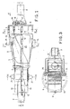
- the number 1 indicates an inlet connection to the purifier, to which is intended to be connected an exhaust pipe 0 of an internal combustion engine.
- the number 2 indicates a connection for a distribution pipe 3 forming part of the gas circuit.
- the connector 1 can advantageously have a circular section, while the connector 2 and the distribution pipe 3 preferably have a rectangular section.
- Said distribution pipe 3, curved and tapered, is directed towards an inlet connection 4 of a vortex chamber defined by a peripheral wall 5 and by a transverse wall 6, in which is hollowed out a central outlet opening 7 connected to an exhaust pipe 8 open to the outside environment.
- the vortex chamber communicates widely with an interior chamber defined by a substantially frustoconical wall 9 which ends in a part of rectangular section 10 which merges, with the inlet fitting 1, into said fitting 2 of the distribution pipe 3.
- a part of the internal surface of the wall 9 is provided with a layer 11 having an effect catalytic, preferably nickel.
- parts 1, 2, 9, 10, and the like described below are preferably part of two shells, a lower shell and an upper shell, tightly connected in a region medium 12.
- the two shells can preferably be made of stainless steel, for example sintered.
- the distribution pipe 3 can, for example, be of stainless steel sheet.
- a body constituting the vortex chamber body which comprises said peripheral wall 5 and the transverse wall 6, as well as a wall 13 constituting a surface spiraloid which, starting at the inlet connection 4, is directed centripetally and ends on a radius substantially corresponding to the radius of the outlet opening 7, as shown in FIG. 6.
- This body can be produced, for example , by a worked fusion of brass, preferably covered with nickel or another suitable metal, at least in part 13 constituting the spiraloid surface. This surface preferably has an exponential development.
- an adjustment valve constituted by a flap 14 pivoted on an axis 15.
- the axis 15 passes through the transverse wall 6 and, outside this wall, carries a lever 16 biased by a spring 17.
- the tension of the spring 15 can optionally be adjustable by means of a screw 18.
- the spring 17 resiliently pushes the flap valve 14 to a position, shown by a solid line in FIG. 6, in which this valve partially throttles the passage in the connector 4, while allowing an elastic displacement of the valve towards a position, indicated in the same figure by broken lines, in which the passage section left free is more extensive.
- a turbine wheel 19 pivoted on an axis 20 which, preferably, has ceramic ceramic ends, and is journalled into ball bearings 21.
- the frustoconical wall 9 has a longitudinal slot 22 communicating with a receiving space defined by a wall 23, provided in the lower part with a discharge plug 24. From the upper part of the internal receiving space to the wall 23 begins a pipe 25, which passes through the wall of the distribution pipe 3 and ends inside this pipe by an end 26 forming an ejector.
- a helical body 27 made of a material having catalytic effect, for example a granular sintered copper, or a thread coated with tantalum, iridium or indium.
- the operation of the device described is as follows.
- the exhaust gases coming from the exhaust pipe 0 of an internal combustion engine arrive at the inlet fitting 1, at the fitting 2 and at the distribution pipe 3, which routes them to the inlet fitting 4 of the chamber. vortex.
- the gases meet the flap valve 14, which directs the flow in a direction tangential to the spiraloid surface 13; the valve 14 moves elastically and automatically under the thrust of the incoming gases, varying the passage section available as a function of the flow rate of the gas flow directed towards the spiraloid surface.
- the gas flow produces, in the interior of the spiraloid surface, an intense vortex; part of the incoming flow is delivered through the outlet opening 7 and discharged into the outside environment, while the rest of the incoming flow is transferred to the interior chamber defined by the frustoconical wall 9.
- the arrangement described constitutes a selector for vortex molecules and, in consideration of the peculiarities of this device and its own inertial and thermodynamic effects, the part of the flux which is conveyed to the outside is fairly cooled and efficiently purified, while the part of the flux which is conveyed to the interior chamber is fairly heated and contains almost all of the impurities originally contained in the incoming gas flow; these impurities therefore have a considerably increased concentration compared to the original.
- the flow licks the helical body 27 and by virtue of the conformation of the body 27, which corresponds substantially to the shape of the gas flow lines, the latter suffers no appreciable resistance to its advancement.
- the helical body 27 exerts its catalytic action on the gases, and this catalytic effect is particularly effective because it is applied to gases in which the temperature and the concentration of the materials to be modified are considerably increased compared to the original ones.
- the catalytic effect in the drying of the walls 9 and 10 of stainless steel, and particularly of the parts of the walls which are provided with the layer 11 of nickel also becomes considerable.
- the gases thus treated arrive at the chamber 10, they pass through the turbine wheel 19 by rotating it, and enter the connector 2 to be recycled.
- the presence of the turbine wheel 19 ensures that the gases entering through the inlet 1 cannot flow back to the chamber 10 instead of entering the fitting 2.
- the gases coming from the inlet 1 and those recycled from the chamber 10 mix, and they are conveyed together by the distribution pipe 3 to the inlet 4 of the vortex chamber.
- the polluted gases are therefore continuously recycled, passing and passing through the vortex chamber and the internal treatment chamber 9, until they have reached a sufficient degree of purification and they are discharged through the opening outlet 7 of the vortex chamber. Consequently, a much more intense purification effect is obtained, the effect that could in any case be achieved by passing gases only, as it turns out in known purifiers.
- the inlet valve 14 of the vortex chamber can be shaped differently, or it can be omitted in applications where the incoming gases have a substantially constant flow rate.
- the slot 22 can be replaced by a section of perforated or mesh walls.
- the turbine wheel 19 can be shaped differently, or it can be replaced by a valve device or, especially in applications with substantially constant flow, by an ejector device.
- the dimensions and proportions of the parts must be commuruted to the expected gas flow rates.
- the walls of the device, and especially the wall 9, can optionally be insulated in order to increase the temperature of the gases during treatment.
Landscapes
- Engineering & Computer Science (AREA)
- Chemical & Material Sciences (AREA)
- Chemical Kinetics & Catalysis (AREA)
- Combustion & Propulsion (AREA)
- Mechanical Engineering (AREA)
- General Engineering & Computer Science (AREA)
- Health & Medical Sciences (AREA)
- Toxicology (AREA)
- Exhaust Gas After Treatment (AREA)
- Processes For Solid Components From Exhaust (AREA)
- Exhaust-Gas Circulating Devices (AREA)
Applications Claiming Priority (2)
| Application Number | Priority Date | Filing Date | Title |
|---|---|---|---|
| IT6731288 | 1988-04-08 | ||
| IT67312/88A IT1219186B (it) | 1988-04-08 | 1988-04-08 | Depuratore per gas di scarico di motori endotermici con selezionatore molecolare a vortice |
Publications (2)
| Publication Number | Publication Date |
|---|---|
| EP0336512A2 true EP0336512A2 (de) | 1989-10-11 |
| EP0336512A3 EP0336512A3 (de) | 1990-01-17 |
Family
ID=11301372
Family Applications (1)
| Application Number | Title | Priority Date | Filing Date |
|---|---|---|---|
| EP89200840A Withdrawn EP0336512A3 (de) | 1988-04-08 | 1989-04-03 | Abgasreiniger für Verbrennungsmotoren mit Wirbel-Molekülabscheider |
Country Status (3)
| Country | Link |
|---|---|
| EP (1) | EP0336512A3 (de) |
| JP (1) | JPH01301914A (de) |
| IT (1) | IT1219186B (de) |
Cited By (1)
| Publication number | Priority date | Publication date | Assignee | Title |
|---|---|---|---|---|
| EP0392575A3 (de) * | 1989-04-12 | 1991-07-24 | I.R.T.I. Istituto Di Ricerca E Trasferimenti Tecnologici Alle Imprese S.R.L. | Abgasreiniger mit katalytischer Aktivität und Schalldämpfer für Brennkraftmaschinen |
Families Citing this family (1)
| Publication number | Priority date | Publication date | Assignee | Title |
|---|---|---|---|---|
| CN105587380B (zh) * | 2016-01-06 | 2018-06-26 | 周飞燕 | 尾气处理装置 |
Family Cites Families (5)
| Publication number | Priority date | Publication date | Assignee | Title |
|---|---|---|---|---|
| US3495385A (en) * | 1967-08-21 | 1970-02-17 | Adolph C Glass | Air pollution control device |
| US3584701A (en) * | 1970-04-07 | 1971-06-15 | Michael W Freeman | Sound and resonance control device |
| US4257225A (en) * | 1978-10-10 | 1981-03-24 | Texaco Inc. | Exhaust gas treatment to reduce particulated solids |
| DE3310933A1 (de) * | 1983-03-25 | 1984-09-27 | Robert Bosch Gmbh, 7000 Stuttgart | Einrichtung zur entfernung von festbestandteilen aus den abgasen von brennkraftmaschinen |
| DE3412081A1 (de) * | 1984-03-31 | 1984-11-15 | Helmut 7101 Löwenstein Hübner | Abgasreiniger |
-
1988
- 1988-04-08 IT IT67312/88A patent/IT1219186B/it active
-
1989
- 1989-04-03 EP EP89200840A patent/EP0336512A3/de not_active Withdrawn
- 1989-04-08 JP JP1089563A patent/JPH01301914A/ja active Pending
Cited By (1)
| Publication number | Priority date | Publication date | Assignee | Title |
|---|---|---|---|---|
| EP0392575A3 (de) * | 1989-04-12 | 1991-07-24 | I.R.T.I. Istituto Di Ricerca E Trasferimenti Tecnologici Alle Imprese S.R.L. | Abgasreiniger mit katalytischer Aktivität und Schalldämpfer für Brennkraftmaschinen |
Also Published As
| Publication number | Publication date |
|---|---|
| JPH01301914A (ja) | 1989-12-06 |
| IT1219186B (it) | 1990-05-03 |
| EP0336512A3 (de) | 1990-01-17 |
| IT8867312A0 (it) | 1988-04-08 |
Similar Documents
| Publication | Publication Date | Title |
|---|---|---|
| EP1846721B1 (de) | Glasschmelzofen | |
| FR2859371A1 (fr) | Dispositif de separation a cyclones et aspirateur comportant un tel dispositif | |
| WO2006063965A1 (fr) | Dispositif d’injection de fluides a l’interieur d’un lit fluidifie rotatif | |
| EP0099818A1 (de) | Einschränkung der Verunreinigung eines Raumes mittels eines Luftvorhangs | |
| EP0336512A2 (de) | Abgasreiniger für Verbrennungsmotoren mit Wirbel-Molekülabscheider | |
| WO2004071623A1 (fr) | Machine rotative destinee a engendrer un flux de fluide epure reglable et capable de s'auto-nettoyer. | |
| EP1951996B1 (de) | Wäscher zur reinigung der abgase eines dieselmotors, betriebsverfahren und entsprechendes seefahrzeug | |
| FR2589194A1 (fr) | Filtre pour la separation de particules solides contenues dans les gaz d'echappement de moteurs diesel | |
| EP0037772B1 (de) | Thermischer Separator mit beweglichem Verteiler | |
| FR2826057A1 (fr) | Dispositif de nettoyage pour l'air de combustion d'un moteur a combustion interne | |
| EP1535561B1 (de) | Abfalltrennvorrichtung für Staubsauger | |
| FR2826059A1 (fr) | Dispositif d'aspiration pour l'air de combustion d'un moteur a combustion interne | |
| FR2776207A1 (fr) | Installation de traitement de gaz par filtre rotatif adsorbant | |
| EP2260188B1 (de) | Vorrichtung mit erhöhter effizienz zur rückgewinnung von öl aus verbrennungsgasen | |
| FR2905425A1 (fr) | Boitier de decantation d'eau pour une ligne d'admission d'air d'un moteur a combustion interne | |
| FR2790545A1 (fr) | Dispositif pour l'extraction de chaleur a partir d'un gaz et four equipe du dispositif | |
| FR2947035A1 (fr) | Refroidissement de paroi de chambre de combustion de moteur a turbine a gaz | |
| FR2790544A1 (fr) | Dispositif pour l'extraction de chaleur a partir de gaz et four equipe du dispositif | |
| BE464228A (de) | ||
| BE517209A (de) | ||
| EP4688215A1 (de) | Gasturbinenprüfstand mit gasabscheidung | |
| CN119212770A (zh) | 空气粗滤器 | |
| FR2863653A1 (fr) | Dispositif de filtrage pour une ligne d'echappement comportant un element de generation d'ecoulement tourbillonnaire | |
| BE369478A (de) | ||
| FR3032894A1 (fr) | Cyclone a prelevement peripherique |
Legal Events
| Date | Code | Title | Description |
|---|---|---|---|
| PUAI | Public reference made under article 153(3) epc to a published international application that has entered the european phase |
Free format text: ORIGINAL CODE: 0009012 |
|
| AK | Designated contracting states |
Kind code of ref document: A2 Designated state(s): BE DE ES FR GB GR NL SE |
|
| PUAL | Search report despatched |
Free format text: ORIGINAL CODE: 0009013 |
|
| AK | Designated contracting states |
Kind code of ref document: A3 Designated state(s): BE DE ES FR GB GR NL SE |
|
| 17P | Request for examination filed |
Effective date: 19900704 |
|
| 17Q | First examination report despatched |
Effective date: 19910905 |
|
| STAA | Information on the status of an ep patent application or granted ep patent |
Free format text: STATUS: THE APPLICATION IS DEEMED TO BE WITHDRAWN |
|
| 18D | Application deemed to be withdrawn |
Effective date: 19921006 |