EP0335397B1 - Tilting collapsible steering column - Google Patents
Tilting collapsible steering column Download PDFInfo
- Publication number
- EP0335397B1 EP0335397B1 EP89105632A EP89105632A EP0335397B1 EP 0335397 B1 EP0335397 B1 EP 0335397B1 EP 89105632 A EP89105632 A EP 89105632A EP 89105632 A EP89105632 A EP 89105632A EP 0335397 B1 EP0335397 B1 EP 0335397B1
- Authority
- EP
- European Patent Office
- Prior art keywords
- wall sections
- tilt bracket
- side wall
- upper clamp
- steering column
- Prior art date
- Legal status (The legal status is an assumption and is not a legal conclusion. Google has not performed a legal analysis and makes no representation as to the accuracy of the status listed.)
- Expired - Lifetime
Links
Images


Classifications
-
- B—PERFORMING OPERATIONS; TRANSPORTING
- B60—VEHICLES IN GENERAL
- B60R—VEHICLES, VEHICLE FITTINGS, OR VEHICLE PARTS, NOT OTHERWISE PROVIDED FOR
- B60R21/00—Arrangements or fittings on vehicles for protecting or preventing injuries to occupants or pedestrians in case of accidents or other traffic risks
- B60R21/02—Occupant safety arrangements or fittings, e.g. crash pads
- B60R21/04—Padded linings for the vehicle interior ; Energy absorbing structures associated with padded or non-padded linings
- B60R21/05—Padded linings for the vehicle interior ; Energy absorbing structures associated with padded or non-padded linings associated with the steering wheel, steering hand lever or steering column
-
- B—PERFORMING OPERATIONS; TRANSPORTING
- B62—LAND VEHICLES FOR TRAVELLING OTHERWISE THAN ON RAILS
- B62D—MOTOR VEHICLES; TRAILERS
- B62D1/00—Steering controls, i.e. means for initiating a change of direction of the vehicle
- B62D1/02—Steering controls, i.e. means for initiating a change of direction of the vehicle vehicle-mounted
- B62D1/16—Steering columns
- B62D1/18—Steering columns yieldable or adjustable, e.g. tiltable
- B62D1/19—Steering columns yieldable or adjustable, e.g. tiltable incorporating energy-absorbing arrangements, e.g. by being yieldable or collapsible
- B62D1/195—Yieldable supports for the steering column
-
- B—PERFORMING OPERATIONS; TRANSPORTING
- B62—LAND VEHICLES FOR TRAVELLING OTHERWISE THAN ON RAILS
- B62D—MOTOR VEHICLES; TRAILERS
- B62D1/00—Steering controls, i.e. means for initiating a change of direction of the vehicle
- B62D1/02—Steering controls, i.e. means for initiating a change of direction of the vehicle vehicle-mounted
- B62D1/16—Steering columns
- B62D1/18—Steering columns yieldable or adjustable, e.g. tiltable
- B62D1/184—Mechanisms for locking columns at selected positions
Definitions
- Another problem is that the impact energy which the breakaway structure can absorb changes largely from the beginning to ending of a collision, i.e., it cannot effect a smooth and stable impact energy absorbing characteristic.
- the upper clamp 4 is generally U-shaped and has upper ends which are bent outwardly to form flanges 48, 48.
- the flanges 48, 48 are formed with bolt holes 40, 40 in which bolts (not shown) are inserted for securing the upper clamp 4 to the lower side of an instrument panel or the like vehicle body section 60.
- the upper clamp 4 further has side wall sections 41, 41 which are respectively formed with elongated rectangular holes 42, 42 elongated upwardly and downwardly.
- the elongated rectangular holes 42, 42 are aligned with each other and slant slightly rearwardly when the upper clamp 4 is installed in place.
- a bolt 5 for adjustment of the relative position between the upper clamp 4 and the tilt bracket 3 is arranged so as to extend through the elongated rectangular holes 42, 42 of the upper clamp 4 and through the holes 36, 36 of the tilt bracket 3 so that the tilt bracket 3 is slidable upwardly and downwardly relative to the upper clamp 4.
- Stopper 6, 6 are installed on the opposite end portions of the bolt 5. The right-hand one of the stoppers 6, 6 is fixedly attached to the bolt 5 and engaged in the elogated hole 42 so as to prevent rotation of the bolt 5 relative to the tilt bracket 3 and the upper clamp 4.
- the tilt bracket 3 and the upper clamp 4 are assembled and installed in such a manner that the stoppers 43, 43 of the upper clamp 4 are spaced from the upstanding end portions 37, 37 of the side wall sections 33, 33 of the tilt bracket 4 a predetermined distance.
- the column jacket 1 of a cross section similar in shape to the cut 31 extends through the inclinded upstanding wall section 30 in such a way as to intersect same at right angles.
- the oval-like shape is desirable since it makes it possible to increase the distance between the column jacket 1 and the side wall sections 33, 33 of the tilt bracket 3.
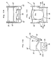
- the inclined upstanding wall section 30 is pushed axially of the steering column 1 and moves together with the steering column 1 into the position shown in Figs. 8A and 8B and then into the position shown in Figs. 8C and 8D while allowing the side wall sections 33, 33 of the tilt bracket 3 to bend and flow inwardly, i.e., toward the inclined upstanding wall sections 30 and finally the side wall sections 33, 33 to shear near the cuts 34, 34.
- the side wall sections 33, 33 are further caused to flow toward the inclined upstanding wall sections 30 in such a way as to extend substantially parallel to the remaining part of the side wall sections 33, 33.
- the impact energy is thus absorbed by the tilt bracket 3 which first deforms plastically and then shears in the above manner, whereby to protect the driver from being injured by the driving wheel, etc. in secondary collision.
- a tilt bracket 3′ according to a modification of the present invention is shown.
- the tilt bracket 3′ has a pair of rounded wall sections 32′, 32′ of a radius or radius of curvature larger than a predetermined value at the opposite lateral ends of the inclined upstanding wall section 30.
- the rounded wall sections 32′, 32′ are in the form of a semicylindrical projection projecting outwardly of the inclined upstanding wall section 30, i.e., in the form of having a semicircular cross section of a predetermined radius.
- the rounded wall sections 32′,32′ may be constructed so as to project outwardly of the side wall sections 33, 33 with respect to the direction in which the side wall sections 33, 33 are opposed.
- the radius or radius of curvature of the rounded wall sections 33, 33 can be increased without substantially increasing the overall size of the tilt bracket 3′.
- the side wall sections 33′, 33′ are respectively bent so that the distance between the side wall sections 33′, 33′ is smaller adjacent the distance piece 35 and larger adjacent the rounded wall sections 32′, 32′ as shown in Figs. 10A to 10C.
- the radius of the curvature of the rounded wall sections 32 ⁇ , 32 ⁇ can be prevented from becoming smaller and maintained substantially unchanged.
- the tilt bracket 3 ⁇ with the rounded wall sections 32 ⁇ , 32 ⁇ and rollers 50, 50 are effective for encouraging the side wall sections 33, 33 to bend and flow toward the inclinded upstanding wall section 30 more smoothly, thus making it possible to attain a smoother and more stable impact energy absorbing characteristic.
- column jacket 1 has been described and shown as being constructed to have an oval-like shape and at the same time the tilt bracket has been described and shown as being formed with the oval-like cut in order to make the tilt bracket as compact as possible, this is not limitative.
- a circular cut may be used in place thereof.
- the oval-like cut may be replaced by an oval-like hole.
Landscapes
- Engineering & Computer Science (AREA)
- Mechanical Engineering (AREA)
- Chemical & Material Sciences (AREA)
- Combustion & Propulsion (AREA)
- Transportation (AREA)
- Steering Controls (AREA)
Description
- The invention relates to a tilting collapsible steering column as indicated in the precharacterizing part of
claim 1. - A tilting collapsible steering column as disclosed in JP-A-50-60526 comprises a tilt bracket welded to a column jacket which is movably supported upon an upper clamp and formed with a slit or cut near the place for connection with the column jacket. With the tilt bracket breakaway structure, it is intended that in collision the tilt bracket shears near the cut while absorbing the impact of the driver hitting the steering wheel as the driver is thrown into it.
- A problem of the tilt bracket breakaway structure is that it cannot absorb the impact energy efficiently since the impact load cannot be transferred to the bracket breakaway structure efficiently.
- Another problem is that the impact energy which the breakaway structure can absorb changes largely from the beginning to ending of a collision, i.e., it cannot effect a smooth and stable impact energy absorbing characteristic.
- A prior art steering column (US-A-4,733,575), as indicated in the precharacterizing part of
claim 1, comprises an energy-absorbing bending bracket for absorbing energy by a permanent deformation thereof when the upper column tube moves axially frontward with respect to the lower column tube. An attachment is fixed to another end of the energy absorbing bending bracket. - It is the object of the invention to provide an improved tilting collapsible steering column which can efficiently and assuredly absorb the impact of the driver in collision and thereby prevent the driver from being injured by the steering wheel, and which can effect a smooth and stable impact energy absorbing characteristic.
- This object is solved by the features as claimed in the characterizing part of
claim 1. -
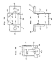
- Fig. 1 is a fragmentary sectional view of a tilting collapsible steering column according to an embodiment of the present invention;
- Fig. 2 is a sectional view taken along the line II-II of Fig. 1;
- Fig. 3A is a side elevatonal view of an upper clamp employed in the steering column of Fig. 1;
- Fig. 3B is a top plan view of the upper clamp of Fig. 3A;
- Fig. 3C is an elevational view of the upper clamp of Fig. 3A;
- Fig. 4A is a side elevational view of a tilt bracket employed in the steering column of Fig. 1;
- Fig. 4B is a top plan view of the tilt bracket of Fig. 4A;
- Fig. 4C is an elevational view of the tilt bracket of Fig. 4A;
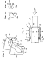
- Fig. 5 is a perspective view of the tilt bracket of Figs. 4A-4C together;
- Figs. 6A and 6B show variations concerning a cut provided to the tilt bracket of Fig. 5; and
- Figs. 7 and 8A-8D are schematic views of the steering column of Fig. 1 in its various operating conditions;
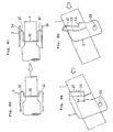
- Figs. 9A-9C are views similar to Fig. 4A-4C but show a tilt bracket according to a modification of the present invention;
- Figs. 10A-10C are views similar to Figs. 4A-4C but show a tilt bracket according to another modification of the present invention;
- Figs. 11A-11C are views simialr to Figs. 4A-4C but show a tilt bracket according to a further modification of the present invention;
- Figs. 12A-12C are views similar to Figs. 4A-4C but show a filt bracket according to a further modification of the present invention;
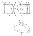
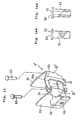
- Figs. 13 is an exploded view of the tilt bracket of Figs. 12A-12C together with rollers;
- Figs. 14A-14B are enlarged elevational, partly sectioned views of the rollers of Fig. 13; and
- Figs. 15A-15D similar to Figs. 8A-8D but show the tilt bracket and rollers of Fig. 13 in their various operating conditions.
- Referring to Figs. 1 and 2, a tilting collapsible steering column according to an embodiment of the present invention is shown as comprising a
column jacket 1, asteering shaft 2, atilt bracket 3 fixedly attached to thecolumn jacket 1 and an upper clamp 4 supporting thecolumn jacket 1 upon avehicle body 60. Thetilt bracket 3 is installed on the upper clamp 4 and slidable upwardly and downwardly relative to same. - As shown in Figs. 3A to 3C, the upper clamp 4 is generally U-shaped and has upper ends which are bent outwardly to form
flanges flanges bolt holes vehicle body section 60. The upper clamp 4 further hasside wall sections rectangular holes rectangular holes side wall sections stoppers abutment faces longer sides rectangular holes stoppers side wall sections side wall sections bottom wall section 44 which is formed with anopening 45 in order to provide theside wall sections donward extensions rectangular holes extensions recess 46 is provided to the corner between eachside wall 41 and eachflange 48 to serve as a stay. Areinforcement 47 in the form of a bent end is provided to eachflange 48 and eachside wall 41. - As shown in Figs. 4A to 4C, the
tilt bracket 3 has a generally channel-like shape and has an inclinedupstanding wall section 30 and a pair ofside wall sections upstanding wall section 30. The inclindedupstanding wall section 30 is generally flat and formed with an oval-like or ellipse-like cut 31 through which thecolumn jacket 1 extends. Specifically, the oval-like cut 31 is in the form of having a pair of semicircularperipheral portions peripheral portion 31a is not completely semicircular, and a pair of parallel straight peripheral portions 31b, 31b between the roughly semicircularperipheral portions tilt bracket 3 further has a pair of roundedcorner sections upstanding wall section 30 and the respectiveside wall sections corner portions side wall sections corner portions upstanding wall section 30 at right angles. - The
column jacket 1 is installed in the oval-like cut 31 so as to extend therethrough and welded to the roughly semicircularperipheral portions tilt bracket 3. Thetilt bracket 3 is formed with slits orcuts column jacket 1. Thecuts upstanding wall section 30 at right angles. Thetilt bracket 3 further has adistance piece 35 extending between the lower portions of theside wall sections holes cuts tilt bracket 3 is installed in place since the impact of the driver is applied horizontally to thesteering column 1. - As shown in Fig. 6A, a
triangular cut 34a may be used in place of thecut 34. Further, as shown in Fig. 6B, another cut 34b shaped so as to have a pair of parallel upper and lower sides and an angled inner side between the parallel upper and lower sides may be used. - As shown in Figs. 1 and 2, a
bolt 5 for adjustment of the relative position between the upper clamp 4 and thetilt bracket 3 is arranged so as to extend through the elongatedrectangular holes holes tilt bracket 3 so that thetilt bracket 3 is slidable upwardly and downwardly relative to the upper clamp 4.Stopper bolt 5. The right-hand one of thestoppers bolt 5 and engaged in theelogated hole 42 so as to prevent rotation of thebolt 5 relative to thetilt bracket 3 and the upper clamp 4. Theother stopper 6 is movable axially of thebolt 6 and engaged in the elongatedrectangular hole 42 so as not to be rotatable relative to thetilt bracket 3 and the upper clamp 4. Anut 8 is screwed onto a threadedportion 5a of thebolt 5 by interposing awasher 7 between thenut 8 and thestopper 6. Thenut 8 is integrally connected to atilt lever 9 to move together therewith. Thestoppers side wall sections nut 8 is tightened by thetilt lever 9. - The
tilt bracket 3 and the upper clamp 4 are assembled and installed in such a manner that thestoppers upstanding end portions side wall sections column jacket 1 of a cross section similar in shape to thecut 31 extends through the inclindedupstanding wall section 30 in such a way as to intersect same at right angles. The oval-like shape is desirable since it makes it possible to increase the distance between thecolumn jacket 1 and theside wall sections tilt bracket 3. - The
column jacket 1 and thesteering shaft 2 are constructed so as to be both telescopical in the axial direction thereof. In this connection, at the place where anupper tube 10 and alower tube 11 constituting thecolumn jacket 1 are fitted together, a recessedportion 12 of theupper tube 10 is forced to contact the outer periphery of thelower tube 12. Further, at the place where anupper shaft 13 and alower shaft 14 constituting thesteering shaft 2 are fitted together, a plurality of radial shear pins 16 formed of synthetic resinous material are engaged in agroove 15 formed in the outer periphery of theupper shaft 13. Though not shown, the lower end portion of thelower shaft 14 is connected through a universal joint to a gear box whereas the upper end portion of theupper shaft 13 is connected to a steering wheel. - In operation, when the
steering column 1 is subjected to an impact load upon secondary collision, the shear pins 16 are broken, thus allowing theupper shaft 13 and thelower shaft 14 to telescope together and at the same time theupper tube 10 and theinner tube 11 to telescope together. By this, thetilt bracket 3 is rotated about thebolt 5 anticlockwise in Fig. 1 since the upper clamp 4 is fixedly attached to thevehicle body 60. The anticlockwise rotation of thetilt bracket 3 causes, as shown in Fig. 7, the upstanding ends 37, 37 of theside wall sections stoppers tilt bracket 3 from rotating further. The impact load is thus received by both thetilt bracket 3 and the upper clamp 4. The inclinedupstanding wall section 30 is pushed axially of thesteering column 1 and moves together with thesteering column 1 into the position shown in Figs. 8A and 8B and then into the position shown in Figs. 8C and 8D while allowing theside wall sections tilt bracket 3 to bend and flow inwardly, i.e., toward the inclinedupstanding wall sections 30 and finally theside wall sections cuts side wall sections tilt bracket 3 occurs near thecuts side wall sections upstanding wall sections 30 in such a way as to extend substantially parallel to the remaining part of theside wall sections tilt bracket 3 which first deforms plastically and then shears in the above manner, whereby to protect the driver from being injured by the driving wheel, etc. in secondary collision. - From the foregoing, it will be understood that the impact of the driver is efficiently transferred or applied to the tilt bracket breakaway structure in secondary collision since the
tilt bracket 3 is adapted to abut upon thestoppers - It will be further understood that the
corner portions upwstanding wall section 30 efficiently. - In Figs. 9A to 9C in which like or corresponding portions to the embodiment of Figs. 4A to 4C are designated by the same reference characters, a
tilt bracket 3′ according to a modification of the present invention is shown. Thetilt bracket 3′ has a pair of roundedwall sections 32′, 32′ of a radius or radius of curvature larger than a predetermined value at the opposite lateral ends of the inclinedupstanding wall section 30. Therounded wall sections 32′, 32′ are in the form of a semicylindrical projection projecting outwardly of the inclinedupstanding wall section 30, i.e., in the form of having a semicircular cross section of a predetermined radius. By the provision of the aboverounded wall sections 32′, 32′, theside wall sections upstanding wall section 30 more smoothly than in case of thetilt bracket 3 of the embodiment of Figs. 4A to 4C. Accordingly, a smoother and more stable shock absorbing characteristic can be attained by thetilt bracket 3′. Except for the above, thetilt bracket 3′ is substantially similar to thetilt bracket 3 of the previous embodiment and can produce subsantially the same effect. - As shown in Figs. 10A to 10C, the
rounded wall sections 32′,32′ may be constructed so as to project outwardly of theside wall sections side wall sections rounded wall sections tilt bracket 3′. For the same end, theside wall sections 33′, 33′ are respectively bent so that the distance between theside wall sections 33′, 33′ is smaller adjacent thedistance piece 35 and larger adjacent therounded wall sections 32′, 32′ as shown in Figs. 10A to 10C. - In Figs. 12A-12C and 13, a
tilt bracket 3˝ according to a further modification of the present invention has a roundedwall sections 32˝, 32˝ substantially similar to therounded wall sections 32′, 32′ in the modification of Figs. 9A to 9C and a pair ofrollers rounded sections 32˝, 32˝, respectively. As shown in Figs. 14A and 14B, therollers solid pin 51 having aflange 53 at one end or in the form of ahollow pin 52 having aflange 53 at one end. Theroller 50 may be made of metal or synthetic resinous material. - With this
tilt bracket 3˝, the inclinedupstanding wall section 30 is pushed axially of thesteering column 1 and moves together with thesteering column 1 into the position shown in Figs. 15A and 15B and then into the position shown in Figs. 15C and 15D while allowing theside wall sections tilt bracket 3 to bend and flow inwardly, i.e., toward the inclinedupstanding wall sections 30 and finally theside wall sections cuts side wall sections tilt bracket 3˝ occurs near thecuts side wall sections upstanding wall sections 30 in such a way as to extend substantially parallel to the remaining part of theside wall sections rounded wall sections 32˝, 32˝ can be prevented from becoming smaller and maintained substantially unchanged. Thetilt bracket 3˝ with therounded wall sections 32˝, 32˝ androllers side wall sections upstanding wall section 30 more smoothly, thus making it possible to attain a smoother and more stable impact energy absorbing characteristic. - While the
column jacket 1 has been described and shown as being constructed to have an oval-like shape and at the same time the tilt bracket has been described and shown as being formed with the oval-like cut in order to make the tilt bracket as compact as possible, this is not limitative. A circular cut may be used in place thereof. Furthermore the oval-like cut may be replaced by an oval-like hole.
Claims (9)
- A tilting collapsible steering column comprising:
an upper clamp (4) secured to a vehicle body (60);
a tilt bracket (3) installed on said upper clamp (4) in such a way as to be moveable upwardly and downwardly relative to said upper clamp (4);
a column jacket (1);
said tilt bracket (3) having an upstanding wall section (30) secured to said column jacket (1) and a pair of side wall sections (33); and
fastening means (5) for releasably securing said tilt bracket (3) to said upper clamp (4);
characterized by
stopper means (43) provided at the upper clamp (4) and engageable with said side wall sections (33) of said tilt bracket (3) for preventing same from rotating about said fastening means (5) relative to said upper clamp (4) when absorbing the impact of the driver in collision,
cuts (34) formed in said side wall sections (33) of the tilt bracket (3) near said column jacket (1) for defining in said side wall sections (33) of the tilt bracket (3), a first portion which is releasably secured to the upper clamp (4) through said fastening means (5) and a second portion connected with said upstanding wall section (30) and thereby encouraging said side wall sections (33) to shear in collision; and
means formed between said upstanding wall section and said second portions of said side wall sections (33) for encouraging said side wall sections (33) to bend and flow toward said upstanding wall sections (30) in collision. - The steering column according to claim 1 wherein said upper clamp (4) has a pair of opposed side wall sections (41), and said stopper means (43) comprises stoppers formed integral with said side wall sections (44) of said upper clamp (4).
- The steering column according to claim 2 wherein said side wall sections (33) of said tilt bracket (3) have edges (37) for abutment with said stoppers (43).
- The steering column according to claim 3 wherein said side wall sections (41) of said upper clamp (4) have elongated holes (42), and said side wall sections (33) of said tilt bracket (3) have bolt holes (36) aligned with said elongated holes (42) of said upper clamp (4), said fastening means including a bolt (5) extending through said elongated holes (42) of said upper clamp (4), and said bolt holes (36) of said tilt bracket (3).
- The steering column according to claim 1 wherein said tilt bracket (3) has rounded corners (32) of a radius of curvature larger than a predetermined value, and said encouraging means is constituted by said rounded corners (32) of said tilt bracket (3).
- The steering column according to claim 1 wherein said tilt bracket (3'') has rounded wall sections (32'') in the form of part-cylindrical projections at the opposite ends of said upstanding wall section (30), and said rounded wall sections (32'') are of a radius of curvature larger than a predetermined value and projecting outwardly of said upstanding wall section (30), said encouraging means being constituted by said rounded wall sections (32'') of said tilt bracket (3'').
- The steering column according to claim 6 wherein said rounded wall sections (32'') of said tilt bracket (3'') further project outwardly of said side wall sections (33) of said tilt bracket (3) with respect to the direction in which said side wall sections (33) are opposed.
- The steering column according to claim 6 wherein said tilt bracket (3) further comprises a distance piece (35) interconnecting lower portions (33a) of said side wall side wall sections (33) of said tilt bracket (3), and said bolt holes (36) are formed in said lower portions (33a) of said side wall sections (33) of said tilt bracket (3), said side wall sections (33) of said tilt bracket (3) being bent so that the distance between said side wall sections (33) is smaller adjacent said distance piece (35) and larger adjacent said rounded wall sections.
- The steering column according to claim 6 wherein said encouraging means further comprises a pair of rollers (50) fitted in said rounded wall sections (32'').
Applications Claiming Priority (6)
| Application Number | Priority Date | Filing Date | Title |
|---|---|---|---|
| JP79305/88 | 1988-03-31 | ||
| JP63079304A JPH0790784B2 (en) | 1988-03-31 | 1988-03-31 | Impact energy absorption tilt type steering column |
| JP63079306A JPH0798488B2 (en) | 1988-03-31 | 1988-03-31 | Shock energy absorption type steering column |
| JP79304/88 | 1988-03-31 | ||
| JP79306/88 | 1988-03-31 | ||
| JP63079305A JPH0796385B2 (en) | 1988-03-31 | 1988-03-31 | Shock energy absorption type steering column |
Publications (3)
| Publication Number | Publication Date |
|---|---|
| EP0335397A2 EP0335397A2 (en) | 1989-10-04 |
| EP0335397A3 EP0335397A3 (en) | 1990-09-12 |
| EP0335397B1 true EP0335397B1 (en) | 1993-11-03 |
Family
ID=27302977
Family Applications (1)
| Application Number | Title | Priority Date | Filing Date |
|---|---|---|---|
| EP89105632A Expired - Lifetime EP0335397B1 (en) | 1988-03-31 | 1989-03-30 | Tilting collapsible steering column |
Country Status (4)
| Country | Link |
|---|---|
| US (1) | US4915412A (en) |
| EP (1) | EP0335397B1 (en) |
| KR (1) | KR920005373B1 (en) |
| DE (1) | DE68910358T2 (en) |
Families Citing this family (35)
| Publication number | Priority date | Publication date | Assignee | Title |
|---|---|---|---|---|
| SE8803943D0 (en) * | 1988-10-31 | 1988-10-31 | Ffv Autotech Ab | STEERING MOUNTING PARTS WITH SLIDING AND TIP FUNCTION |
| US5009121A (en) * | 1989-07-07 | 1991-04-23 | Nippon Seiko Kabushiki Kaisha | Telescopic steering column device |
| DE3925706C1 (en) * | 1989-08-03 | 1991-01-31 | Dr.Ing.H.C. F. Porsche Ag, 7000 Stuttgart, De | |
| US5117707A (en) * | 1990-02-23 | 1992-06-02 | Fuji Kiko Company, Limited | Tilting steering column |
| US5052715A (en) * | 1990-03-19 | 1991-10-01 | Ford Motor Company | Passive impact restraining vehicular steering column assembly |
| US5375881A (en) * | 1990-09-05 | 1994-12-27 | Rolls-Royce Motor Cars Limited | Energy absorption system including a U-shaped deformable member and a deforming member |
| GB9019408D0 (en) * | 1990-09-05 | 1990-10-17 | Rolls Royce Motor Cars | Energy absorption system |
| JP2513633Y2 (en) * | 1990-11-02 | 1996-10-09 | 日本精工株式会社 | Shock absorption type steering column device |
| US5222410A (en) * | 1991-01-31 | 1993-06-29 | Fuji Kiko Co., Ltd. | Steering column assembly |
| JP2989680B2 (en) * | 1991-02-15 | 1999-12-13 | 株式会社山田製作所 | Tilt and telescopic steering system |
| FR2688182B1 (en) * | 1992-03-04 | 1994-06-10 | Ecia Equip Composants Ind Auto | STEERING COLUMN ADJUSTABLE IN POSITION FOR MOTOR VEHICLE. |
| US5439252A (en) * | 1993-04-22 | 1995-08-08 | Trw Inc. | Dual pivot steering column |
| DE4322636C2 (en) * | 1993-07-07 | 2002-08-22 | Supervis Vaduz Ets | Safety steering for motor vehicles |
| US5356179A (en) * | 1993-09-13 | 1994-10-18 | Chrysler Corporation | Energy absorbing device for a steering column |
| US5613404A (en) * | 1994-03-07 | 1997-03-25 | Case Corporation | Tiltable steering mechanism for an off-highway implement |
| US5390956A (en) * | 1994-05-17 | 1995-02-21 | Chrysler Corporation | Steering column assembly |
| JPH08150943A (en) * | 1994-11-30 | 1996-06-11 | Fuji Kiko Co Ltd | Tilt steering column |
| WO1997010136A1 (en) * | 1995-09-11 | 1997-03-20 | Nastech Europe Limited | Adjustable vehicle steering column clamping mechanism |
| US5706704A (en) * | 1996-03-25 | 1998-01-13 | General Motors Corporation | Energy absorbing steering column for motor vehicle |
| US5692778A (en) * | 1996-11-14 | 1997-12-02 | General Motors Corporation | Motor vehicle steering column |
| JP2000127991A (en) * | 1998-10-30 | 2000-05-09 | Nsk Ltd | Shock absorbing steering device and automobile |
| GB2374324B (en) * | 1998-10-30 | 2003-04-23 | Nsk Ltd | Shock absorbing steering apparatus |
| WO2002053445A2 (en) * | 2001-01-02 | 2002-07-11 | Visteon Global Technologies, Inc. | Plastic metal hybrid steering column for automotive applications |
| JP3940319B2 (en) * | 2002-06-05 | 2007-07-04 | 株式会社ジェイテクト | Shock absorbing steering device |
| JP2004067034A (en) * | 2002-08-09 | 2004-03-04 | Fuji Kiko Co Ltd | Steering column |
| JP2005075250A (en) * | 2003-09-03 | 2005-03-24 | Nsk Ltd | Shock absorbing steering column device with telescopic mechanism |
| US7267370B2 (en) * | 2004-03-11 | 2007-09-11 | Delphi Technologies, Inc. | Frequency and stiffness enhancement mechanization |
| EP1698787A3 (en) * | 2005-03-05 | 2008-07-30 | Dana Corporation | Method of manufacturing an axially collapsible splined assembly |
| US7882761B2 (en) * | 2008-01-05 | 2011-02-08 | Nexteer (Beijing) Technology Co., Ltd. | Adjustable steering column assembly with compressive locking mechanism |
| KR20120006163A (en) * | 2010-07-12 | 2012-01-18 | 주식회사 만도 | Tilt hinge bracket of steering wheel of automobile and steering column of automobile having same |
| US8973944B2 (en) * | 2012-05-31 | 2015-03-10 | Steering Solutions Ip Holding Corporation | System and method for attaching a steering column to a vehicle structure |
| JP6192108B2 (en) * | 2013-12-26 | 2017-09-06 | 株式会社ジェイテクト | Pin assembly and steering device |
| DE102014111775B4 (en) | 2014-08-18 | 2020-06-04 | Thyssenkrupp Ag | Steering column for a motor vehicle |
| DE102016218271A1 (en) * | 2016-09-22 | 2018-03-22 | Thyssenkrupp Ag | Sheath unit for an adjustable steering column of a motor vehicle |
| US11007958B2 (en) | 2019-04-17 | 2021-05-18 | Ford Global Technologies, Llc | Cross-vehicle pivoting steering assembly |
Family Cites Families (3)
| Publication number | Priority date | Publication date | Assignee | Title |
|---|---|---|---|---|
| US3811337A (en) * | 1973-04-04 | 1974-05-21 | Ford Motor Co | Energy absorbing steering column for motor vehicles |
| US4273005A (en) * | 1979-04-20 | 1981-06-16 | Ford Motor Company | Steering column assembly |
| JPH0517342Y2 (en) * | 1986-04-17 | 1993-05-10 |
-
1989
- 1989-03-28 US US07/330,344 patent/US4915412A/en not_active Expired - Lifetime
- 1989-03-30 EP EP89105632A patent/EP0335397B1/en not_active Expired - Lifetime
- 1989-03-30 DE DE89105632T patent/DE68910358T2/en not_active Expired - Fee Related
- 1989-03-31 KR KR1019890004269A patent/KR920005373B1/en not_active Expired
Also Published As
| Publication number | Publication date |
|---|---|
| DE68910358T2 (en) | 1994-03-03 |
| US4915412A (en) | 1990-04-10 |
| KR920005373B1 (en) | 1992-07-02 |
| DE68910358D1 (en) | 1993-12-09 |
| KR890014305A (en) | 1989-10-23 |
| EP0335397A2 (en) | 1989-10-04 |
| EP0335397A3 (en) | 1990-09-12 |
Similar Documents
| Publication | Publication Date | Title |
|---|---|---|
| EP0335397B1 (en) | Tilting collapsible steering column | |
| EP0659615B1 (en) | Pedal arrangement for a vehicle | |
| US4989898A (en) | Energy absorption type steering apparatus | |
| US5503431A (en) | Adjustable energy absorbing steering column with adjustment disabled during collision | |
| EP1395479B1 (en) | Improved steering column for a vehicle | |
| EP2636573B1 (en) | Steering column assist device | |
| US4061054A (en) | Steering wheel | |
| JP2008230555A (en) | Steering device | |
| EP1518775B1 (en) | Shock absorbing steering column device for vehicle | |
| EP0769444B1 (en) | Steering column for automotive vehicle | |
| US4998999A (en) | Steering column assembly with energy absorption mechanism | |
| US5228359A (en) | Steering column bracket assembly | |
| JP3409572B2 (en) | Shock absorbing steering column device | |
| EP0764108B1 (en) | Separable connecting device for a steering column | |
| US4660852A (en) | Crash energy absorber for a vehicle steering wheel | |
| EP0928733B1 (en) | Steering column for automotive vehicle | |
| US20040195816A1 (en) | Steering tilt column assembly for vehicle | |
| US6343523B1 (en) | Longitudinal guidance control system for telescopic shafts and/or assemblies with collapsing mechanisms in motor vehicle steering columns | |
| EP0240116A1 (en) | A vehicle with a collapsible steering column assembly | |
| US3934486A (en) | Safety steering column | |
| JPH0790784B2 (en) | Impact energy absorption tilt type steering column | |
| JP2997614B2 (en) | Shock absorbing steering device | |
| JPH0796385B2 (en) | Shock energy absorption type steering column | |
| JPS61125963A (en) | Tilt steering column device | |
| JP3110663B2 (en) | Tilt steering column |
Legal Events
| Date | Code | Title | Description |
|---|---|---|---|
| PUAI | Public reference made under article 153(3) epc to a published international application that has entered the european phase |
Free format text: ORIGINAL CODE: 0009012 |
|
| 17P | Request for examination filed |
Effective date: 19890330 |
|
| AK | Designated contracting states |
Kind code of ref document: A2 Designated state(s): DE GB |
|
| PUAL | Search report despatched |
Free format text: ORIGINAL CODE: 0009013 |
|
| AK | Designated contracting states |
Kind code of ref document: A3 Designated state(s): DE GB |
|
| 17Q | First examination report despatched |
Effective date: 19920720 |
|
| GRAA | (expected) grant |
Free format text: ORIGINAL CODE: 0009210 |
|
| AK | Designated contracting states |
Kind code of ref document: B1 Designated state(s): DE GB |
|
| REF | Corresponds to: |
Ref document number: 68910358 Country of ref document: DE Date of ref document: 19931209 |
|
| PLBE | No opposition filed within time limit |
Free format text: ORIGINAL CODE: 0009261 |
|
| STAA | Information on the status of an ep patent application or granted ep patent |
Free format text: STATUS: NO OPPOSITION FILED WITHIN TIME LIMIT |
|
| 26N | No opposition filed | ||
| REG | Reference to a national code |
Ref country code: GB Ref legal event code: IF02 |
|
| PGFP | Annual fee paid to national office [announced via postgrant information from national office to epo] |
Ref country code: DE Payment date: 20060323 Year of fee payment: 18 |
|
| PGFP | Annual fee paid to national office [announced via postgrant information from national office to epo] |
Ref country code: GB Payment date: 20060329 Year of fee payment: 18 |
|
| GBPC | Gb: european patent ceased through non-payment of renewal fee |
Effective date: 20070330 |
|
| PG25 | Lapsed in a contracting state [announced via postgrant information from national office to epo] |
Ref country code: DE Free format text: LAPSE BECAUSE OF NON-PAYMENT OF DUE FEES Effective date: 20071002 |
|
| PG25 | Lapsed in a contracting state [announced via postgrant information from national office to epo] |
Ref country code: GB Free format text: LAPSE BECAUSE OF NON-PAYMENT OF DUE FEES Effective date: 20070330 |