EP0335329A2 - Pneumatisches Schlagwerkzeug - Google Patents
Pneumatisches Schlagwerkzeug Download PDFInfo
- Publication number
- EP0335329A2 EP0335329A2 EP89105456A EP89105456A EP0335329A2 EP 0335329 A2 EP0335329 A2 EP 0335329A2 EP 89105456 A EP89105456 A EP 89105456A EP 89105456 A EP89105456 A EP 89105456A EP 0335329 A2 EP0335329 A2 EP 0335329A2
- Authority
- EP
- European Patent Office
- Prior art keywords
- vibro
- sleeve
- casing
- tool
- impact tool
- Prior art date
- Legal status (The legal status is an assumption and is not a legal conclusion. Google has not performed a legal analysis and makes no representation as to the accuracy of the status listed.)
- Granted
Links
Images
Classifications
-
- B—PERFORMING OPERATIONS; TRANSPORTING
- B25—HAND TOOLS; PORTABLE POWER-DRIVEN TOOLS; MANIPULATORS
- B25D—PERCUSSIVE TOOLS
- B25D17/00—Details of, or accessories for, portable power-driven percussive tools
- B25D17/04—Handles; Handle mountings
- B25D17/043—Handles resiliently mounted relative to the hammer housing
-
- B—PERFORMING OPERATIONS; TRANSPORTING
- B25—HAND TOOLS; PORTABLE POWER-DRIVEN TOOLS; MANIPULATORS
- B25D—PERCUSSIVE TOOLS
- B25D17/00—Details of, or accessories for, portable power-driven percussive tools
- B25D17/11—Arrangements of noise-damping means
- B25D17/12—Arrangements of noise-damping means of exhaust silencers
-
- B—PERFORMING OPERATIONS; TRANSPORTING
- B25—HAND TOOLS; PORTABLE POWER-DRIVEN TOOLS; MANIPULATORS
- B25D—PERCUSSIVE TOOLS
- B25D17/00—Details of, or accessories for, portable power-driven percussive tools
- B25D17/24—Damping the reaction force
-
- B—PERFORMING OPERATIONS; TRANSPORTING
- B25—HAND TOOLS; PORTABLE POWER-DRIVEN TOOLS; MANIPULATORS
- B25D—PERCUSSIVE TOOLS
- B25D9/00—Portable percussive tools with fluid-pressure drive, i.e. driven directly by fluids, e.g. having several percussive tool bits operated simultaneously
- B25D9/14—Control devices for the reciprocating piston
Definitions
- the invention relates to a pneumatic impact tool compri literallysing a body of a pneumatic motor which body is separated from a body-casing of the impact tool by means of a vibro-isolating system, an air feeder sytem, a noise suppressor having a double-chamber, and a working tool slidably connected with a tool sleeve.
- Such a pneumatic impact tool is particularly designed for cleaning castings in foundries.
- PL-B-128 491 discloses a pneumatic hammer provided with a casing inside of which a working cylinder in form of a pipe is mounted and fitted with a ram moving in a sleeve along its axis.
- the hammer comprises a sealing sleeve fixed in the hammer casing an the level of air inlets that open into the working cylinder.
- the sleeve closes the air inlets as the working cylinder is in rest-point. This hammer does not have any vibro-isolation that would sufficiently comply with vibration standards being in force.
- the pneumatic hammer disclosed in PL-B-122 477 has the same disadvantages.
- This hammer is provided with at least two bolts and adequate springs, a barrel holder slidably mounted on a ring protrusion of the barrel, an elastic ring fixed with its outer diameter in the hammer casing and with its inner diameter on the barrel as well as a flanged sleeve inside of which the barrel slides.
- the bolts passing through the elastic ring connect the holder and the sleeve by means of nuts, springs and a flange.
- the hammer according to PL-B-122 381 comprises a vibro-isolator with a negative elastic compensation and a performance range of its vibro-isolation that is very narrow. So it cannot be used in the miniaturization of hand-held tools as it is required.
- a disadvantage of this hammer is also a bracket grip supported with a thin rod only.
- the working tool has a flange protecting it from falling down during operation and resting, when said impact tool is being pressed down, on a thrust ring which is mounted on a barrel seat, in that one of the chambers of the noise suppressor consists of a conic sleeve pushed on the body-casing such that it can rotate around its axis, and is connected with the other chamber, defined by a space between the body-casing and the body of the pneumatic motor, by means of orifices forming an acute angle with the main symmetry-axis of the impact tool and extending tangentially to the plane of the body of the pneumatic motor, in that the body of the pneumatic motor is connected with a vibro-isolator having a constant interaction force by means of vibro-isolating spacers and releasable fasteners, in that between the body-casing and a grip an additional vibro-isolation is provided consisting of a vibro-isolator having a constant interaction force by means of vibr
- a shaped groove is provided in the body-casing in which cams of the vibro-isolator having a constant interaction force are mounted and fixed by the washers made of elastic material.
- a rubber-spring sleeve that acts as a vibro-isolated grip of the the operator's left hand is screwed on the body-casing.
- the design of the pneumatic impact tool according to the invention prevents the operator from being overstrained by holding-down forces, so it provides safe and hygenic working with higher productivity. Moreover, the tool has an entire vibration protection of the operator's both hands in all directions of vibration. The left-hand grip of the tool prevents the operator from directly touching the working tool strongly activated by vibrations and protects him against noxious effects of vibrations.
- the above described compressed air supply systems suppresses any uplift pressure that would change under the effect of air pressure fluctuations and would cause vibrations of the pipe.
- the diameter of the air supply orifices in the sleeve and that of the supply pipe are matched such that the tool can sag in a pre-set range when the feeder is entirely switched on.
- the hammer operation is stable in the full range of amplitudes of the body of the pneumatic motor and of the body-casing where both hand-grips for the operator are mounted.
- the tool is further provided with an automatic lock-out of the air supply system in order to protect the casing of the pneumatic motor against strokes and the operator's both hands against additional vibrations.
- the double-chamber noise suppressor applied in the tool is designed such that the operator is capable of setting the direction of the air out-flow.
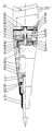
- the pneumatic impact tool shown in the drawing comprises a pneumatic motor separated from a body-casing 4 by means of a vibro-isolating system, a supply or air feeder system, a double-chamber noise suppressor and a working tool which is slidably connected with a tool sleeve.
- the pneumatic motor includes a ram moving to-and-fro in a barrel provided in its one end with a distributor slider body in which an air distribution slider moves.
- the distribution slider body is pressed against a barrel face by a barrel head that is screwed on the barrel and fastened by a pin and a ring.
- the other end of the barrel comprises a tool sleeve 3 pushed in the barrel seat.
- a thrust ring 2 is mounted in the bottom of the barrel seat.
- the working tool 1 moves in the tool sleeve 3 and rests on the thrust ring 2 as the impact or hammer tool is being pressed down against the material to be worked on.
- the tool sleeve 3, the barrel, the distributor slider body, the air distribution slider and the barrel head compose the body of the pneumatic motor.
- the body of the pneumatic motor is separated from the body-casing 4 by means of a vibrator-isolating system that consists of a constant interaction force vibro-isolator and silent block guides.
- the constant interaction force vibro-isolator is connected in series with a washer 5 made of an elastic material of vibro-isolator characteristic and with sleeves 6.
- These sleeves 6 together with bolts 7 and washers 8 fasten a guide 9 of the vibro-isolator to a barrel head 31. While working guide rollers 10 of a carriage 11 of the vibro-isolator roll on the guide 9.
- the carriage 11 acts at the same time as a guide for the spring system of the vibro-isolator.
- the central rollers of the carriage 11 roll on cambers of the cams 12 that are mounted in shaped grooves 13 in the body-casing 4.
- the cams 12 are protected from falling out of the grooves 13 by a vibro-isolationg spacer 14 that is pressed against the cams 12 by vibro-isolating sleeves 15 and releasable fasteners 16 with washers 17.
- the body of the pneumatic motor is guided in the body-casing 4 by two guides, an upper and a lower one that are also the first stage of vibro-isolation between the body of the pneumatic motor and the hand grips for the operator.
- the upper guide consists of a slide bearing in form of a sleeve 18 that is made of a material characterized by a low friction factor and that is mounted in the vibro-isolating sleeve 19 firmly connected to the body-casing 4.
- the lower guide consists of a sleeve 20 with a multi-slot shaped orifice.
- the sleeve 20 is connected with an oval sleeve 22 through a layer 21 of vibro-isolating material.
- the sleeve 22 is pushed in the body-casing 4.
- the sleeve 20 matches with the tool sleeve 3.
- the supply or air feeder system is provided with a cut-off valve that is connected to a lever being located in the operators left hand grip 23.
- the lever directly affects the valve head mounted in the operator's right hand grip.
- a spring pressing the head against the seat causes the valve to close.
- a sealing consists of one additional gasket made of an elastic material.
- the sleeve 25 is made of a material characterized by a low friction factor and by high vibro-isolation properties.
- the pipe 24, the one end of which is blanked off has two small holes 26 extending perpendicularly to the symmetry axis of the impact tool.
- the holes 26 are in line of two openings 29 in the sleeve 25.
- An indirect supplying is possible right after pressing the grip 23, that gives the hole 27 a bigger diameter, being also provided in the pipe 24 but perpendicular to the holes 26 and overlapping with two subsequent holes 29 perpendicular to the holes 26.
- the holes 28 of the pipe 24 are open parallel to the holes 26. After the vibro-isolator with constant reaction force deflects so as the holes 28 come in line with the holes 29, the feed passage is entirely opened.
- the supply air after having passed through the holes 28 and 29, flows through a chamber 30 between the sleeve 25 and a seat of the barrel head 31, parallel to the symmetry axis of the tool and then through air passages 32 in the barrel head 31 to the air distributor slider body.
- the air distribution slider controls the air flow and guides it alternately above or below the ram causing the ram to move to-and-fro.
- the position of the air distribution slider depends on the position of the ram causing the hammer tool to start to work automatically after switching the air supply on.
- the air flows out of the pneumatic motor and comes into the space between the body of the pneumatic motor and the body-casing 4, i.e. the first air decompression chamber 33. Then the air flows through the outflow suppressor on the body-casing 4 through wall holes 35.
- the outer wall of the outflow supressor consists of the conic sleeve 34 made of an elastic light material, where several outlet holes 36 open. The air is led down from the operator.
- the chamber of the sleeve 25 in the supply system is additionally decompressed in front of the supply face of the sleeve.
- the purpose is to decompress the body-casing 4 with the body of the pneumatic motor that would take place in case of closing of that chamber.
- the additional vibro-isolation of both grips ensures complete vibro-isolation of the hammer tool.
- the second stage of the vibro-isolation of the operator's left hand consists of a sleeve 37 that is made of a material characterized by a high vibration damping coefficient and that is screwed on the body-casing 4 by means of a spring emersed in this sleeve 37.
- the second stage of the vibro-isolation of the operator's right hand consists of an elestic washer and an elastic sleeve.
- the supply system is also double-isolated.
- the first stage consists of the sleeve 25 made of a material characterized by a high vibration damping coefficient and mounted in the body of the pneumatic motor.
- the second stage consists of an elastic layer 38 by means of which the pipe 24 is installed in the operator's right hand grip 23.
- the hammer tool is designed in a streamline shape, so its form is esthetic and makes operation more easy.
Landscapes
- Engineering & Computer Science (AREA)
- Mechanical Engineering (AREA)
- Physics & Mathematics (AREA)
- Fluid Mechanics (AREA)
- Percussive Tools And Related Accessories (AREA)
- Vibration Prevention Devices (AREA)
- Electrophonic Musical Instruments (AREA)
- Earth Drilling (AREA)
Applications Claiming Priority (2)
| Application Number | Priority Date | Filing Date | Title |
|---|---|---|---|
| PL1988271527A PL153526B1 (en) | 1988-03-29 | 1988-03-29 | Pneumatic impact tool |
| PL271527 | 1988-03-29 |
Publications (3)
| Publication Number | Publication Date |
|---|---|
| EP0335329A2 true EP0335329A2 (de) | 1989-10-04 |
| EP0335329A3 EP0335329A3 (de) | 1991-08-21 |
| EP0335329B1 EP0335329B1 (de) | 1994-08-24 |
Family
ID=20041352
Family Applications (1)
| Application Number | Title | Priority Date | Filing Date |
|---|---|---|---|
| EP89105456A Expired - Lifetime EP0335329B1 (de) | 1988-03-29 | 1989-03-28 | Pneumatisches Schlagwerkzeug |
Country Status (10)
| Country | Link |
|---|---|
| US (1) | US5052499A (de) |
| EP (1) | EP0335329B1 (de) |
| JP (1) | JPH01289678A (de) |
| AT (1) | ATE110316T1 (de) |
| CS (1) | CS194089A2 (de) |
| DD (1) | DD283576A5 (de) |
| DE (1) | DE68917626T2 (de) |
| HU (1) | HU209840B (de) |
| PL (1) | PL153526B1 (de) |
| YU (1) | YU64489A (de) |
Families Citing this family (8)
| Publication number | Priority date | Publication date | Assignee | Title |
|---|---|---|---|---|
| US5419404A (en) * | 1990-05-23 | 1995-05-30 | Bretec Oy | Hydraulic impact hammer |
| US5322131A (en) * | 1993-05-20 | 1994-06-21 | Chicago Pneumatic Tool Company | Vibration-reduced pneumatic tool |
| US5813477A (en) * | 1996-05-23 | 1998-09-29 | Chicago Pneumatic Tool Company | Vibration-reduced impact tool and vibration isolator therefor |
| DE19646622B4 (de) * | 1996-11-12 | 2004-07-01 | Wacker Construction Equipment Ag | An einem Handgriff führbares Arbeitsgerät |
| US6932166B1 (en) | 2002-12-03 | 2005-08-23 | Paul Kirsch | Pneumatic tool |
| US7478096B2 (en) * | 2003-02-26 | 2009-01-13 | Burnside Acquisition, Llc | History preservation in a computer storage system |
| GB0428348D0 (en) * | 2004-12-24 | 2005-02-02 | Bamford Excavators Ltd | Percussion power tool apparatus |
| US20160271780A1 (en) * | 2015-03-19 | 2016-09-22 | Jhih Jhong Lin | Shock Absorption Device for Pneumatic Tool |
Family Cites Families (7)
| Publication number | Priority date | Publication date | Assignee | Title |
|---|---|---|---|---|
| GB399773A (en) * | 1932-09-12 | 1933-10-12 | Frank Hills | Improvements in or relating to pneumatic hammers and similar percussive tools |
| US2019964A (en) * | 1933-02-20 | 1935-11-05 | Independent Pneumatic Tool Co | Cushion means for tools |
| US3640351A (en) * | 1970-05-18 | 1972-02-08 | Gardner Denver Co | Force pulse shaping member for percussion tool |
| US4071094A (en) * | 1973-06-21 | 1978-01-31 | Viktor Evdokimovich Kilin | Portable pneumatic percussive tool |
| US4327807A (en) * | 1978-09-19 | 1982-05-04 | Maco-Meudon | Percussion tool casing |
| US4366870A (en) * | 1979-10-31 | 1983-01-04 | Frederick Leonard L | Pile hammer cushion block |
| US4402369A (en) * | 1981-05-26 | 1983-09-06 | Moskovskoe Vysshee Technicheskoe Uchilische | Pneumatic tool |
-
1988
- 1988-03-29 PL PL1988271527A patent/PL153526B1/pl unknown
-
1989
- 1989-03-16 US US07/325,302 patent/US5052499A/en not_active Expired - Fee Related
- 1989-03-28 DE DE68917626T patent/DE68917626T2/de not_active Expired - Fee Related
- 1989-03-28 EP EP89105456A patent/EP0335329B1/de not_active Expired - Lifetime
- 1989-03-28 DD DD89326945A patent/DD283576A5/de not_active IP Right Cessation
- 1989-03-28 AT AT89105456T patent/ATE110316T1/de not_active IP Right Cessation
- 1989-03-29 CS CS891940A patent/CS194089A2/cs unknown
- 1989-03-29 YU YU00644/89A patent/YU64489A/xx unknown
- 1989-03-29 JP JP1077952A patent/JPH01289678A/ja active Pending
- 1989-03-29 HU HU891579A patent/HU209840B/hu not_active IP Right Cessation
Also Published As
| Publication number | Publication date |
|---|---|
| PL271527A1 (en) | 1989-10-02 |
| CS194089A2 (en) | 1991-09-15 |
| HUT50695A (en) | 1990-03-28 |
| ATE110316T1 (de) | 1994-09-15 |
| EP0335329A3 (de) | 1991-08-21 |
| HU209840B (en) | 1994-11-28 |
| US5052499A (en) | 1991-10-01 |
| PL153526B1 (en) | 1991-04-30 |
| JPH01289678A (ja) | 1989-11-21 |
| DE68917626T2 (de) | 1995-02-16 |
| YU64489A (en) | 1991-04-30 |
| DE68917626D1 (de) | 1994-09-29 |
| EP0335329B1 (de) | 1994-08-24 |
| DD283576A5 (de) | 1990-10-17 |
Similar Documents
| Publication | Publication Date | Title |
|---|---|---|
| US4040554A (en) | Pneumatic apparatus | |
| US5322131A (en) | Vibration-reduced pneumatic tool | |
| EP0335329A2 (de) | Pneumatisches Schlagwerkzeug | |
| EP1539424B1 (de) | Schleuderstrahlvorrichtung | |
| US2019964A (en) | Cushion means for tools | |
| US2372029A (en) | Pneumatic hammer | |
| US3939925A (en) | Throttle valve construction for a percussion tool | |
| GB1354648A (en) | Control valve in a pressure fluid operated tool | |
| ATE292533T1 (de) | Nietwerkzeug | |
| EP1007288A1 (de) | Druckluftbetätigtes schlagwerk | |
| US2120992A (en) | Pneumatic tool | |
| GB2138728A (en) | Pneumatic impact tool | |
| GB1040830A (en) | Improvements in means for preventing idle operation of percussion tools | |
| IE852685L (en) | Sunscreen composition for hair protection | |
| US3437013A (en) | Valve assembly for a pneumatically actuated fastener driving tool | |
| US763887A (en) | Pneumatic rivet-holder. | |
| WO1997007378A3 (en) | Abrasive blasting head | |
| SU996727A2 (ru) | Пневматический перфоратор | |
| US1303297A (en) | Apparatus for pneumatic control | |
| JPS5935748B2 (ja) | 衝撃作動空気工具 | |
| US3181591A (en) | Shut-off plug for a blast tip | |
| US1479320A (en) | Rivet breaker or cutter | |
| RU1792828C (ru) | Пневматический инструмент | |
| SU507383A2 (ru) | Пневматический клеймитель | |
| SU1020516A1 (ru) | Пневмомолот |
Legal Events
| Date | Code | Title | Description |
|---|---|---|---|
| PUAI | Public reference made under article 153(3) epc to a published international application that has entered the european phase |
Free format text: ORIGINAL CODE: 0009012 |
|
| AK | Designated contracting states |
Kind code of ref document: A2 Designated state(s): AT DE FR GB IT SE |
|
| PUAL | Search report despatched |
Free format text: ORIGINAL CODE: 0009013 |
|
| AK | Designated contracting states |
Kind code of ref document: A3 Designated state(s): AT DE FR GB IT SE |
|
| 17P | Request for examination filed |
Effective date: 19911128 |
|
| 17Q | First examination report despatched |
Effective date: 19930217 |
|
| GRAA | (expected) grant |
Free format text: ORIGINAL CODE: 0009210 |
|
| AK | Designated contracting states |
Kind code of ref document: B1 Designated state(s): AT DE FR GB IT SE |
|
| PG25 | Lapsed in a contracting state [announced via postgrant information from national office to epo] |
Ref country code: IT Free format text: LAPSE BECAUSE OF FAILURE TO SUBMIT A TRANSLATION OF THE DESCRIPTION OR TO PAY THE FEE WITHIN THE PRE;WARNING: LAPSES OF ITALIAN PATENTS WITH EFFECTIVE DATE BEFORE 2007 MAY HAVE OCCURRED AT ANY TIME BEFORE 2007. THE CORRECT EFFECTIVE DATE MAY BE DIFFERENT FROM THE ONE RECORDED.SCRIBED TIME-LIMIT Effective date: 19940824 Ref country code: AT Effective date: 19940824 |
|
| REF | Corresponds to: |
Ref document number: 110316 Country of ref document: AT Date of ref document: 19940915 Kind code of ref document: T |
|
| REF | Corresponds to: |
Ref document number: 68917626 Country of ref document: DE Date of ref document: 19940929 |
|
| ET | Fr: translation filed | ||
| EAL | Se: european patent in force in sweden |
Ref document number: 89105456.1 |
|
| PG25 | Lapsed in a contracting state [announced via postgrant information from national office to epo] |
Ref country code: GB Effective date: 19950328 |
|
| PG25 | Lapsed in a contracting state [announced via postgrant information from national office to epo] |
Ref country code: SE Effective date: 19950329 |
|
| PLBE | No opposition filed within time limit |
Free format text: ORIGINAL CODE: 0009261 |
|
| STAA | Information on the status of an ep patent application or granted ep patent |
Free format text: STATUS: NO OPPOSITION FILED WITHIN TIME LIMIT |
|
| PGFP | Annual fee paid to national office [announced via postgrant information from national office to epo] |
Ref country code: FR Payment date: 19950705 Year of fee payment: 7 |
|
| 26N | No opposition filed | ||
| GBPC | Gb: european patent ceased through non-payment of renewal fee |
Effective date: 19950328 |
|
| PG25 | Lapsed in a contracting state [announced via postgrant information from national office to epo] |
Ref country code: DE Effective date: 19951201 |
|
| EUG | Se: european patent has lapsed |
Ref document number: 89105456.1 |
|
| PG25 | Lapsed in a contracting state [announced via postgrant information from national office to epo] |
Ref country code: FR Effective date: 19961129 |
|
| REG | Reference to a national code |
Ref country code: FR Ref legal event code: ST |