EP0334974B1 - Terminals arrangement for printed-circuit boards - Google Patents
Terminals arrangement for printed-circuit boards Download PDFInfo
- Publication number
- EP0334974B1 EP0334974B1 EP88104910A EP88104910A EP0334974B1 EP 0334974 B1 EP0334974 B1 EP 0334974B1 EP 88104910 A EP88104910 A EP 88104910A EP 88104910 A EP88104910 A EP 88104910A EP 0334974 B1 EP0334974 B1 EP 0334974B1
- Authority
- EP
- European Patent Office
- Prior art keywords
- terminal
- terminals
- circuit board
- conductor
- conductor connection
- Prior art date
- Legal status (The legal status is an assumption and is not a legal conclusion. Google has not performed a legal analysis and makes no representation as to the accuracy of the status listed.)
- Expired - Lifetime
Links
Images

Classifications
-
- H—ELECTRICITY
- H01—ELECTRIC ELEMENTS
- H01R—ELECTRICALLY-CONDUCTIVE CONNECTIONS; STRUCTURAL ASSOCIATIONS OF A PLURALITY OF MUTUALLY-INSULATED ELECTRICAL CONNECTING ELEMENTS; COUPLING DEVICES; CURRENT COLLECTORS
- H01R12/00—Structural associations of a plurality of mutually-insulated electrical connecting elements, specially adapted for printed circuits, e.g. printed circuit boards [PCB], flat or ribbon cables, or like generally planar structures, e.g. terminal strips, terminal blocks; Coupling devices specially adapted for printed circuits, flat or ribbon cables, or like generally planar structures; Terminals specially adapted for contact with, or insertion into, printed circuits, flat or ribbon cables, or like generally planar structures
- H01R12/50—Fixed connections
- H01R12/51—Fixed connections for rigid printed circuits or like structures
- H01R12/515—Terminal blocks providing connections to wires or cables
-
- H—ELECTRICITY
- H01—ELECTRIC ELEMENTS
- H01R—ELECTRICALLY-CONDUCTIVE CONNECTIONS; STRUCTURAL ASSOCIATIONS OF A PLURALITY OF MUTUALLY-INSULATED ELECTRICAL CONNECTING ELEMENTS; COUPLING DEVICES; CURRENT COLLECTORS
- H01R9/00—Structural associations of a plurality of mutually-insulated electrical connecting elements, e.g. terminal strips or terminal blocks; Terminals or binding posts mounted upon a base or in a case; Bases therefor
- H01R9/22—Bases, e.g. strip, block, panel
- H01R9/24—Terminal blocks
- H01R9/26—Clip-on terminal blocks for side-by-side rail- or strip-mounting
- H01R9/2625—Clip-on terminal blocks for side-by-side rail- or strip-mounting with built-in electrical component
Definitions
- the invention relates to a printed circuit board terminal arrangement consisting of functional terminals such as disconnect and fuse terminals and conductor connection terminals.
- functional terminals such as disconnect and fuse terminals and conductor connection terminals.
- all function terminals such as, for example, disconnect terminals and fuse terminals, are also provided with their own conductor connection.
- disconnect terminals and fuse terminals are also provided with their own conductor connection.
- they can be combined as desired and arranged in blocks and connected to the printed circuit board, but such an arrangement leads to an extremely space-consuming and costly construction.
- the present invention is therefore based on the object of providing a printed circuit board terminal arrangement which enables all desired arrangement combinations to be carried out with significantly reduced design complexity and with considerable space savings.
- the solution according to the invention consists in that the function terminals are kept without a conductor connection, their housings can be mechanically connected to those of the conductor connection terminals and also with one another, and they can be electrically connected to the conductor connections of the connection terminals via conductor tracks of the circuit board and / or other functional elements. Thanks to this design principle, there is a circuit board terminal system in which the function terminals no longer have their own conductor connections. This means that they can be manufactured considerably more cost-effectively and also require significantly less space.
- the new terminal system also makes it easy for the terminal manufacturer to provide the user with prefabricated, assembled terminal blocks on request.
- conductor connection terminals also includes commercially available prefabricated conductor connection terminal strips with a predetermined number of poles.
- the housings of the functional terminals are provided on all sides with the connecting elements for the mechanical housing connection.
- the function terminals can thus not only be blocked with the conductor connection terminals, but also in any arrangement with one another, be it side by side or one behind the other.
- Individual conductor connection terminals are expedient, with the exception of the conductor connection side, provided on three sides with the connecting elements in order to be able to implement any desired combination, also with respect to the spatial positions of the terminals to one another.
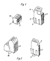
- a conductor connecting terminal 1a in the form of a three-pole strip piece is first illustrated in FIG. Except for the conductor connection side on all three other sides, the conductor connection terminal 1a has mechanical connecting elements for connection to the housings of further terminals for the terminal arrangement to be formed, dovetail webs 2 and / or corresponding dovetail grooves 3 in the exemplary embodiment shown. It is understood that deviating from the exemplary embodiment shown, the Conductor terminal 1a could also be composed of individual terminal elements, as illustrated, for example, in FIG. 2 in connection with another type of another conductor terminal.
- a fuse terminal 4 is shown as an example of a function terminal in the context of the circuit board terminal arrangement concerned here.
- the fuse terminal 4 has mechanical connecting elements on its housing on all four sides, again as dovetail webs and / or dovetail grooves 2, 3.
- the conductor connection terminal 1b can also be a double-level terminal, which is either again designed as a strip of a certain number of poles or, as shown, is assembled from individual elements.
- FIG. 2 also illustrates a disconnect terminal 5 as a function terminal, which is likewise provided on all sides with mechanical connecting elements on its housing, in the exemplary embodiment again in the form of dovetail-shaped webs and dovetail grooves 2, 3.
- FIGS. 3 and 4 illustrate different circuit board terminal arrangements according to the invention, wherein in FIG. 3 a conductor terminal 1a in the form of a certain number of poles is combined with both a fuse terminal 4 and a disconnect terminal 5.
- a conductor terminal 1b in the form of a two-level terminal composed of elements is in turn assembled with a fuse terminal 4 and a disconnect terminal 5.
- FIG. 4 it is possible to add numerous function terminals, which can then also be mechanically blocked with one another via the lateral mechanical connecting elements.
- the blocked terminals as a whole are located on a printed circuit board 6, the conductor tracks of which are used for the electrical connection of the conductor connections in the conductor connection terminals 1a, 1b with the elements to be supplied with current in the disconnect and fuse terminals 4, 5.
- a conductor connecting terminal 1 a which is designed with two poles, is directly combined on its rear side with a fuse terminal 4, with which, in turn, a disconnect terminal 5 is combined on its rear side.
- a series connection can be made here in such a way that one of the conductor connections of the conductor connection terminal 1a is connected to the fuse terminal 4 via a conductor track of the circuit board, while this is then connected to the disconnect terminal 5 via a further conductor track section.
- the second pole of the conductor terminal 1 a can then be used for other purposes.
- the individual terminal types required for the PCB terminal block arrangement can either be made available to the user by the manufacturer for their free combination, or can be supplied combined in prefabricated block arrangements, in which case the user only has to insert the block into the circuit board and the corresponding solder joints for the electrical connection.
Description
Die Erfindung betrifft eine Leiterplattenklemmanordnung, bestehend aus Funktionsklemmen wie beispielsweise Trenn- und Sicherungsklemmen sowie Leiteranschlußklemmen. Bei den bekannten Leiterplattenklemmenanordnungen sind neben den separaten Leiteranschlußklemmen auch alle Funktionsklemmen wie beispielsweise Trennklemmen und Sicherungsklemmen, mit einem eigenen Leiteranschluß versehen. Sie sind zwar insoweit beliebig kombinierbar und zu Blöcken anzuordnen und mit der Leiterplatte zu verbinden, doch führt eine solche Anordnung zu einem außerordentlich platz- und kostenintensiven Aufbau. Der vorliegenden Erfindung liegt von daher die Aufgabe zugrunde, eine Leiterplattenklemmenanordnung zu schaffen, die alle gewünschten Anordnungskombinationen mit erheblich verringertem konstruktiven Aufwand sowie mit erheblicher Platzersparnis ermöglicht.The invention relates to a printed circuit board terminal arrangement consisting of functional terminals such as disconnect and fuse terminals and conductor connection terminals. In the known circuit board terminal arrangements, in addition to the separate conductor connection terminals, all function terminals, such as, for example, disconnect terminals and fuse terminals, are also provided with their own conductor connection. In this respect, they can be combined as desired and arranged in blocks and connected to the printed circuit board, but such an arrangement leads to an extremely space-consuming and costly construction. The present invention is therefore based on the object of providing a printed circuit board terminal arrangement which enables all desired arrangement combinations to be carried out with significantly reduced design complexity and with considerable space savings.
Die erfindungsgemäße Lösung besteht darin, daß die Funktionsklemmen leiteranschlußlos gehalten sind, ihre Gehäuse mit denen der Leiteranschlußklemmen sowie auch untereinander mechanisch verbindbar sind und sie elektrisch mit den Leiteranschlüssen der Anschlußklemmen über Leiterbahnen der Leiterplatte und/oder anderen Funktionselementen verbindbar sind.
Dank dieses Konstruktionsprinzipes ergibt sich ein Leiterplattenklemmensystem, bei dem die Funktionsklemmen keine eigenen Leiteranschlüsse mehr haben. Sie lassen sich damit erheblich kostengünstiger herstellen und haben auch einen deutlich verringerten Raumbedarf.The solution according to the invention consists in that the function terminals are kept without a conductor connection, their housings can be mechanically connected to those of the conductor connection terminals and also with one another, and they can be electrically connected to the conductor connections of the connection terminals via conductor tracks of the circuit board and / or other functional elements.
Thanks to this design principle, there is a circuit board terminal system in which the function terminals no longer have their own conductor connections. This means that they can be manufactured considerably more cost-effectively and also require significantly less space.
Zwar sind bei diesem System grundsätzlich immer zwei Klemmen erforderlich,nämlich neben der Funktionsklemme eine Anschlußklemme, doch führt das System aus den genannten Gründen bei der üblichen Blockbildung aus einer Vielzahl von Funktions- und Leiteranschlußklemmen im Endergebnis zu einer außerordentlichen Kosteneinsparung bei deutlich verringertem Raumbedarf. Über die Vielzahl mechanischer Verbindungen zwischen den Gehäusen der verschiedenen Klemmentypen kommt es innerhalb größerer Blockanordnungen zu einer hohen Gestaltfestigkeit des Blockes. Hervorzuheben ist insbesondere auch, daß es durch die Benutzung der Leiterbahnen der Leiterplatte für die elektrische Verbindung insbesondere zwischen den Funktionsklemmen und den Leiteranschlußklemmen zu einer außerordentlich hohen Anzahl von Lötverbindungspunkten zwischen dem Klemmenblock und der Leiterplatte kommt, so daß eine derartige BLockanordnung auch einen außerordentlich sicheren Halt auf der Leiterplatte hat. Es sind im Grunde genommen beliebige Kombinationen innerhalb der Blockanordnung zu verwirklichen. So ist es insbesondere auch im Bedarfsfall problemlos möglich, eine Funktionsklemme mit der Leiteranschlußklemme auf dem Weg über eine weitere Funktionsklemme zu verbinden, also insoweit eine zweckmäßige Reihenschaltung der Funktionsklemmen untereinander unter Inanspruchnahme nur einer Leiteranschlußklemme zu verwirklichen.In principle, two terminals are always required in this system, namely a connection terminal in addition to the function terminal, but for the reasons mentioned above, the system leads to extraordinary cost savings with significantly reduced space requirements in the usual block formation from a large number of function and conductor connection terminals. The large number of mechanical connections between the housings of the different types of terminals results in a high structural strength of the block within larger block arrangements. It should also be emphasized in particular that the use of the conductor tracks of the printed circuit board for the electrical connection, in particular between the functional terminals and the conductor connecting terminals, leads to an extraordinarily high number of solder connection points between the terminal block and the printed circuit board, so that such a block arrangement also provides an extraordinarily secure hold on the circuit board. Basically, any combinations within the block arrangement can be realized. In particular, it is easily possible, if necessary, to connect a function terminal to the conductor connection terminal on the way via a further function terminal, that is to say, in this respect to implement a suitable series connection of the function terminals with one another using only one conductor connection terminal.
Das neue Klemmensystem ermöglicht es auch problemlos für den Klemmenhersteller, dem Anwender auf dessen Wunsch hin entsprechend vorgefertigte zusammengesetzte Klemmenblöcke zur Verfügung zu stellen.The new terminal system also makes it easy for the terminal manufacturer to provide the user with prefabricated, assembled terminal blocks on request.
Es ist hervorzuheben, daß , wenn vorstehend von Leiteranschlußklemmen gesprochen wird, hierunter auch handelsübliche vorgefertigte Leiteranschlußklemmenleisten vorbestimmter Polzahl zu verstehen sind.It should be emphasized that if the term “conductor connection terminals” is used above, this also includes commercially available prefabricated conductor connection terminal strips with a predetermined number of poles.
In weiterer sehr zweckmäßiger Ausgestaltung sind die Gehäuse der Funktionsklemmen allseitig mit den Verbindungselementen für die mechanische Gehäuseverbindung versehen. Die Funktionsklemmen können somit nicht nur mit den Leiteranschlußklemmen verblockt werden, sondern auch in beliebiger Anordnung untereinander, sei es nun nebeneinander oder hintereinander. Einzelne Leiteranschlußklemmen sind dabei zweckmäßig, mit Ausnahme der Leiteranschlußseite, dreiseitig mit den Verbindungselementen versehen, um jede gewünschte Kombination, auch bezüglich der Raumlagen der Klemmen zueinander, verwirklichen zu können.In a further very expedient embodiment, the housings of the functional terminals are provided on all sides with the connecting elements for the mechanical housing connection. The function terminals can thus not only be blocked with the conductor connection terminals, but also in any arrangement with one another, be it side by side or one behind the other. Individual conductor connection terminals are expedient, with the exception of the conductor connection side, provided on three sides with the connecting elements in order to be able to implement any desired combination, also with respect to the spatial positions of the terminals to one another.
Ausführungsbeispiele von Leiterplattenklemmenanordnungen gemäß der Erfindung werden nachstehend unter Bezugnahme auf die Zeichnung näher beschrieben.
Es zeigen
- Figur 1
- eine erste Ausführungsform einer Leiteranschlußklemme und einer Funktionsklemme als Sicherungsklemme für die erfindungsgemäße Leiterplattenklemmenanordnung,
Figur 2- eine weitere Ausführungsform mit einer weiteren Leiteranschlußklemmengestaltung und einer weiteren Funktionsklemme als Trennklemme,
Figuren 3 und 4- Beispiele für zusammengesetzte Leiterplattenklemmenanordnungen gemäß der Erfindung, angeordnet auf der Leiterplatte,
Figur 5- ein mechanisch-elektrisches Illustrationsschema für verschiedene Blockbildungsmöglichkeiten bei einer Leiterplattenklemmenanordnung gemäß der Erfindung.
Show it
- Figure 1
- a first embodiment of a conductor terminal and a functional terminal as a fuse terminal for the circuit board terminal arrangement according to the invention,
- Figure 2
- another embodiment with a further conductor terminal design and a further function terminal as a disconnect terminal,
- Figures 3 and 4
- Examples of composite circuit board terminal arrangements according to the invention, arranged on the circuit board,
- Figure 5
- a mechanical-electrical illustration scheme for various block formation options in a circuit board terminal arrangement according to the invention.
Als ein Element einer Leiterplattenklemmenanordnung ist in Figur 1 zunächst eine Leiteranschlußklemme 1a in Form eines dreipoligen Leistenstückes illustriert. Die Leiteranschlußklemme 1a hat bis auf die Leiteranschlußseite auf allen drei anderen Seiten mechanische Verbindungselemente zur Verbindung mit den Gehäusen weiterer Klemmen für die zu bildende Klemmenanordnung, im dargestellten Ausführungsbeispiel Schwalbenschwanzstege 2 und/oder entsprechende Schwalbenschwanznuten 3. Es versteht sich, daß abweichend von dargestellten Ausführungsbeispiel die Leiteranschlußklemme 1a auch aus einzelnen Anschlußklemmenelementen zusammengesetzt sein könnte, wie es beispielsweise in Figur 2 im Zusammenhang mit einem anderen Typ einer anderen Leiteranschlußklemme illustriert ist.As an element of a printed circuit board terminal arrangement, a
Als Beispiel für eine Funktionsklemme im Rahmen der hier betroffenen Leiterplattenklemmenanordnung ist eine Sicherungsklemme 4 dargestellt. Die Sicherungsklemme 4 hat an ihrem Gehäuse auf allen vier Seiten mechanische Verbindungselemente, wiederum als Schwalbenschwanzstege und/oder Schwalbenschwanznuten 2, 3.A
In Figur 2 ist illustriert, daß die Leiteranschlußklemme 1b auch eine Doppelstockklemme sein kann, die entweder wieder als Leistenstück bestimmter Polzahl ausgebildet ist, oder aber, wie dargestellt, aus Einzelementen zusammengefügt ist. In Figur 2 ist ferner als Funktionsklemme eine Trennklemme 5 illustriert, die ebenfalls allseitig mit mechanischen Verbindungselementen an ihrem Gehäuse, im Ausführungsbeispiel wiederum in Form schwalbenschwanzförmiger Stege und Schwalbenschwanznuten 2, 3, versehen ist.In FIG. 2 it is illustrated that the conductor connection terminal 1b can also be a double-level terminal, which is either again designed as a strip of a certain number of poles or, as shown, is assembled from individual elements. FIG. 2 also illustrates a
Die Figuren 3 und 4 illustrieren unterschiedliche Leiterplattenklemmenanordnungen gemäß der Erfindung, wobei in Figur 3 eine Leiteranschlußklemme 1a in Leistenform bestimmter Polzahl sowohl mit einer Sicherungsklemme 4 wie mit einer Trennklemme 5 kombiniert ist. In Figur 4 ist eine Leiteranschlußklemme 1b in Form einer elementweise zusammengesetzten zweistöckigen Klemme wiederum mit einer Sicherungsklemme 4 sowie einer Trennklemme 5 zusammengefügt. Es sind dabei aus Gründen der klareren Darstellungsweise lediglich nur eine Sicherungsklamme 4 und eine Trennklemme 5 dargestellt. Im Rahmen des Blocksystemes ist die Hinzufügung zahlreicher Funktionsklemmen, die dann auch untereinander mechanisch über die seitlichen mechanischen Verbindungselemente gehäusemäßig verblockt werden können, möglich. Die verblockten Klemmen insgesamt befinden sich auf einer Leiterplatte 6, deren Leiterbahnen für die elektrische Verbindung der Leiteranschlüsse in den Leiteranschlußklemmen 1a, 1b mit den mit Strom zu beaufschlagenden Elementen in den Trenn- und Sicherungsklemmen 4, 5 benutzt werden.FIGS. 3 and 4 illustrate different circuit board terminal arrangements according to the invention, wherein in FIG. 3 a
Diese Art der elektrischen und mechanischen Verknüpfung ist in der Illustrationsskizze der Figur 5 erläutert. Im oberen Teil der Darstellung ist beispielsweise eine Leiteranschlußklemme 1a, die zweipolig ausgebildet ist, auf ihrer Rückseite unmittelbar mit einer Sicherungsklemme 4 kombiniert, mit der wiederum auf ihrer Rückseite eine Trennklemme 5 kombiniert ist. Mechanisch geschieht dies über die mechanischen Verbindungselemente an den Gehäusen, die auf allen denkbaren Kombinationsflächen vorgesehen sind. Elektrisch kann hier eine Reihenschaltung derart vorgenommen werden, daß man über eine Leiterbahn der Leiterplatte einen der Leiteranschlüsse der Leiteranschlußklemme 1a mit der Sicherungsklemme 4 verbindet, während man diese dann über einen weiteren Leiterbahnabschnitt mit der Trennklemme 5 verbindet. Der zweite Pol der Leiteranschlußklemme 1a kann dann anderweitig genutzt werden. Im unteren Teil der Darstellung der Figur 5 ist der Anwendungsfall illustriert, daß eine gesonderte Beschaltung der Sicherungsklemme 4 und der Trennklemme 5 gewünscht ist. Man nimmt dann beispielsweise eine dreipolige Leiteranschlußklemme 1a, verknüpft diese auf ihrer gesamten Rückseite mit der Sicherungsklemme 4 und der Trennklemme 5, wobei nun die Trennklemme 5 nicht hinter, sondern neben der Sicherungsklemme 4 steckt. Die beiden Funktionsklemmen können gehäusemäßig über die mechanischen Verbindungselemente verblockt werden. Elektrisch werden über entsprechende Leiterbahnen der Leiterplatte zwei Leiteranschlüsse der Leiteranschlußklemme 1a mit der Sicherungsklemme 4 verbunden, während ein Leiteranschluß der Leiteranschlußklemme 1a mit der Trennklemme 5 verbunden wird.This type of electrical and mechanical connection is explained in the illustration sketch in FIG. 5. In the upper part of the illustration, for example, a
Die für die Leiterplattenklemmenanordnung benötigten einzelnen Klemmentypen können vom Hersteller dem Anwender entweder zu dessen freier Kombination zur Verfügung gestellt, oder aber auf Wunsch in vorgefertigten Blockanordnungen kombiniert geliefert werden, wobei in letzterem Fall der Anwender nur noch den Block in die Leiterplatte einzufügen und die entsprechenden Lötstellen für die elektrische Verknüpfung zu setzen hat.The individual terminal types required for the PCB terminal block arrangement can either be made available to the user by the manufacturer for their free combination, or can be supplied combined in prefabricated block arrangements, in which case the user only has to insert the block into the circuit board and the corresponding solder joints for the electrical connection.
Mit dem illustrierten und beschriebenen Klemmenanordnungssystem sind auch ohne weiteres weitere Bauelemente kombinierbar, soweit diese dann gehäusemäßig für die mechanische Verknüpfung ausgestaltet sind und im übrigen zum Aufsetzen auf und Verbinden mit einer Leiterplatte ausgelegt sind. Zu denken ist beispielsweise an die Möglichkeit zusätzlicher Kontrollen durch die Anknüpfung von Anzeigebausteinen und dergleichen.With the illustrated and described terminal arrangement system, further components can also be combined without further ado, insofar as these are then designed for mechanical connection in the housing and are otherwise designed to be placed on and connected to a printed circuit board. One example is the possibility of additional controls by connecting display modules and the like.
Claims (5)
- A printed circuit board terminal arrangement comprising function terminals such as fuse and disconnect terminals (4, 5) and conductor connection terminals (1a, 1b), characterised in that the function terminals (4, 5) are kept free of a conductor connection, their housings can be mechanically connected to those of the conductor connection terminals (1a, 1b) and also to each other by means of mechanical connecting elements (2, 3) arranged on sides of the terminals, and they can be electrically connected to the conductor connections of the conductor connection terminals (1a, 1b) by way of conductor tracks of the printed circuit board (6) and/or other function terminals.
- A printed circuit board terminal arrangement according to claim 1 characterised in that the function terminals (4, 5) have the mechanical connecting elements (2, 3) on their housings on all sides.
- A printed circuit board terminal arrangement according to claim 1 or claim 2 characterised in that the conductor connection terminals (1a, 1b) have the mechanical connecting elements (2, 3) on their free combination sides, with the exception of the conductor connection side.
- A printed circuit board terminal arrangement according to one of the preceding claims characterised in that two different function terminals (4, 5) are arranged one behind the other relative to the conductor connection terminal (1a, 1b) and the function terminal (5) which is at the rear in the series circuit is connected by way of the front function terminal (4) to the conductor connection terminal (1a, 1b).
- A printed circuit board terminal arrangement according to one of the preceding claims characterised in that the individual terminal types (1a, 1b, 4, 5) are assembled in the desired number and the desired arrangement to provide a prefabricated block by means of the mechanical connecting elements (2, 3).
Priority Applications (3)
| Application Number | Priority Date | Filing Date | Title |
|---|---|---|---|
| DE8888104910T DE3883210D1 (en) | 1988-03-26 | 1988-03-26 | PCB TERMINAL ARRANGEMENT. |
| EP88104910A EP0334974B1 (en) | 1988-03-26 | 1988-03-26 | Terminals arrangement for printed-circuit boards |
| US07/327,698 US4929186A (en) | 1988-03-26 | 1989-03-23 | Circuit board terminal assembly |
Applications Claiming Priority (1)
| Application Number | Priority Date | Filing Date | Title |
|---|---|---|---|
| EP88104910A EP0334974B1 (en) | 1988-03-26 | 1988-03-26 | Terminals arrangement for printed-circuit boards |
Publications (2)
| Publication Number | Publication Date |
|---|---|
| EP0334974A1 EP0334974A1 (en) | 1989-10-04 |
| EP0334974B1 true EP0334974B1 (en) | 1993-08-11 |
Family
ID=8198845
Family Applications (1)
| Application Number | Title | Priority Date | Filing Date |
|---|---|---|---|
| EP88104910A Expired - Lifetime EP0334974B1 (en) | 1988-03-26 | 1988-03-26 | Terminals arrangement for printed-circuit boards |
Country Status (3)
| Country | Link |
|---|---|
| US (1) | US4929186A (en) |
| EP (1) | EP0334974B1 (en) |
| DE (1) | DE3883210D1 (en) |
Families Citing this family (5)
| Publication number | Priority date | Publication date | Assignee | Title |
|---|---|---|---|---|
| FR2730572B1 (en) * | 1995-02-10 | 1997-03-14 | Schneider Electric Sa | INTERFACE DEVICE |
| DE202006017882U1 (en) * | 2006-11-22 | 2007-03-01 | Cedes Ag | Cartridge e.g. electronic control cartridge, for safety device e.g. light grid, has housing with rear mounting side and connector area on front side, where additional connector area is formed between front side and rear mounting side |
| DE202007005373U1 (en) * | 2007-04-12 | 2008-08-21 | Weidmüller Interface GmbH & Co. KG | Modular terminal block system |
| DE102009013689A1 (en) * | 2009-03-20 | 2010-09-23 | Phoenix Contact Gmbh & Co. Kg | Device for fixing multiple electrical connecting terminals, has fuse element which is arranged such that fuse element encompasses connection block along its circumferential surfaces in partial manner |
| DE102018109861A1 (en) * | 2018-04-24 | 2019-10-24 | Phoenix Contact Gmbh & Co. Kg | Connector assembly for a terminal block |
Family Cites Families (10)
| Publication number | Priority date | Publication date | Assignee | Title |
|---|---|---|---|---|
| US3171939A (en) * | 1961-05-25 | 1965-03-02 | Buchanan Electrical Prod Corp | Switch type terminal block |
| US4029914A (en) * | 1976-04-14 | 1977-06-14 | A P Products Incorporated | Multiple switch mechanism |
| GB1553921A (en) * | 1976-09-01 | 1979-10-10 | Amp Inc | Electrical junction box |
| US4171862A (en) * | 1977-04-09 | 1979-10-23 | Ellenberger & Poensgen Gmbh | Terminal board for electrical equipment |
| DE2722736C2 (en) * | 1977-05-17 | 1982-04-08 | Auergesellschaft Gmbh, 1000 Berlin | Multipole connector strip |
| US4227238A (en) * | 1977-09-28 | 1980-10-07 | Nippon Gakki Seizo Kabushiki Kaisha | Mounting and electrical connection means for operation unit for electric devices |
| DE3227819C2 (en) * | 1982-07-26 | 1985-09-05 | Siemens AG, 1000 Berlin und 8000 München | Connector with insertable fuse |
| JPS6016110A (en) * | 1983-07-05 | 1985-01-26 | 住友電気工業株式会社 | Device for mutually connecting wire ring harness |
| JPS6075903A (en) * | 1983-09-30 | 1985-04-30 | Matsushita Electric Works Ltd | Sequence controller |
| DE8515405U1 (en) * | 1985-05-24 | 1985-08-01 | Metalluk Bauscher GmbH & Co KG, 8600 Bamberg | Device for clamping the ends of electrical wires in clamping bodies with a fuse |
-
1988
- 1988-03-26 EP EP88104910A patent/EP0334974B1/en not_active Expired - Lifetime
- 1988-03-26 DE DE8888104910T patent/DE3883210D1/en not_active Expired - Fee Related
-
1989
- 1989-03-23 US US07/327,698 patent/US4929186A/en not_active Expired - Lifetime
Also Published As
| Publication number | Publication date |
|---|---|
| US4929186A (en) | 1990-05-29 |
| EP0334974A1 (en) | 1989-10-04 |
| DE3883210D1 (en) | 1993-09-16 |
Similar Documents
| Publication | Publication Date | Title |
|---|---|---|
| EP0116519B1 (en) | Building block, in particular for building-block toys | |
| DE4005049A1 (en) | ELECTRICAL CONNECTION HOUSING | |
| DE4227182C1 (en) | Central unit | |
| DE3048451A1 (en) | Simple centralised electrical unit for vehicle - has insulating boards between metal circuit boards with connections for plug-on components | |
| EP0222030B1 (en) | Initiator terminal block | |
| DE2812332C3 (en) | Multiple connector for cards with printed circuit boards | |
| EP0334974B1 (en) | Terminals arrangement for printed-circuit boards | |
| DE3001870C2 (en) | ||
| DE2708291A1 (en) | Terminal block formed from matching sections - has plastic housing with code pattern for plugs and holes for printed circuit use | |
| DE2847116C2 (en) | Cable connection for telephone exchanges | |
| WO2012171565A1 (en) | Electrical contact device for connecting circuit boards | |
| DE3627899C1 (en) | Electrical plug connector | |
| DE3442056A1 (en) | Plug connector device | |
| DE2907207A1 (en) | Switchable plug connector system - has two printed circuit boards for short circuiting specified contacts of phase conductors | |
| DE102011001486A1 (en) | Direct connector for e.g. mechanically connecting printed circuit boards to form backplane utilized for creating transmission links between different electronic devices, has terminal rails connected with each other and arranged in T-shape | |
| DE19524850C2 (en) | Electrical connection terminal for printed circuit boards | |
| CH607542A5 (en) | Printed circuit board mechanical coding system | |
| DE2455845C3 (en) | Component for the fast, in particular experimental, construction of electrical or electronic circuits | |
| EP0547532A1 (en) | Disposition of BCU-unit and means for a separable connection to a BUS-line | |
| DE2527813A1 (en) | Electronic circuit bus-bar assembly - has metal strips with pin connectors, embedded in insulating block having separating walls | |
| DE2046729B2 (en) | Test clip providing solderless couplings of integrated components - has side pieces supporting connecting bridges at right angles above contact springs in chambers opening towards inside | |
| EP0746064B1 (en) | Terminal block for circuit boards | |
| DE7414444U (en) | Electrical connection terminal, especially switchgear terminal block | |
| DE4412016C1 (en) | Supporting plate with bus=bars for cable distribution cabinet | |
| DE1590612A1 (en) | Wiring matrix |
Legal Events
| Date | Code | Title | Description |
|---|---|---|---|
| PUAI | Public reference made under article 153(3) epc to a published international application that has entered the european phase |
Free format text: ORIGINAL CODE: 0009012 |
|
| 17P | Request for examination filed |
Effective date: 19890104 |
|
| AK | Designated contracting states |
Kind code of ref document: A1 Designated state(s): CH DE FR GB IT LI |
|
| RAP1 | Party data changed (applicant data changed or rights of an application transferred) |
Owner name: WEIDMUELLER INTERFACE GMBH & CO. |
|
| 17Q | First examination report despatched |
Effective date: 19921130 |
|
| GRAA | (expected) grant |
Free format text: ORIGINAL CODE: 0009210 |
|
| AK | Designated contracting states |
Kind code of ref document: B1 Designated state(s): CH DE FR GB IT LI |
|
| PG25 | Lapsed in a contracting state [announced via postgrant information from national office to epo] |
Ref country code: IT Free format text: LAPSE BECAUSE OF FAILURE TO SUBMIT A TRANSLATION OF THE DESCRIPTION OR TO PAY THE FEE WITHIN THE PRE;WARNING: LAPSES OF ITALIAN PATENTS WITH EFFECTIVE DATE BEFORE 2007 MAY HAVE OCCURRED AT ANY TIME BEFORE 2007. THE CORRECT EFFECTIVE DATE MAY BE DIFFERENT FROM THE ONE RECORDED.SCRIBED TIME-LIMIT Effective date: 19930811 |
|
| GBT | Gb: translation of ep patent filed (gb section 77(6)(a)/1977) |
Effective date: 19930812 |
|
| REF | Corresponds to: |
Ref document number: 3883210 Country of ref document: DE Date of ref document: 19930916 |
|
| ET | Fr: translation filed | ||
| PLBE | No opposition filed within time limit |
Free format text: ORIGINAL CODE: 0009261 |
|
| STAA | Information on the status of an ep patent application or granted ep patent |
Free format text: STATUS: NO OPPOSITION FILED WITHIN TIME LIMIT |
|
| 26N | No opposition filed | ||
| REG | Reference to a national code |
Ref country code: CH Ref legal event code: PL |
|
| REG | Reference to a national code |
Ref country code: CH Ref legal event code: AEN Free format text: DAS PATENT IST AM 30.11.1995, GESTUETZT AUF DAS AM 29.09.1995 EINGEREICHTE WIEDEREINSETZUNGSGESUCH, AUF GRUND VON ART. 47 PATG, WIEDER IN KRAFT GESETZT WORDEN. |
|
| REG | Reference to a national code |
Ref country code: GB Ref legal event code: IF02 |
|
| PGFP | Annual fee paid to national office [announced via postgrant information from national office to epo] |
Ref country code: DE Payment date: 20050309 Year of fee payment: 18 |
|
| PGFP | Annual fee paid to national office [announced via postgrant information from national office to epo] |
Ref country code: CH Payment date: 20050310 Year of fee payment: 18 |
|
| PGFP | Annual fee paid to national office [announced via postgrant information from national office to epo] |
Ref country code: FR Payment date: 20050311 Year of fee payment: 18 |
|
| PGFP | Annual fee paid to national office [announced via postgrant information from national office to epo] |
Ref country code: GB Payment date: 20050314 Year of fee payment: 18 |
|
| PG25 | Lapsed in a contracting state [announced via postgrant information from national office to epo] |
Ref country code: GB Free format text: LAPSE BECAUSE OF NON-PAYMENT OF DUE FEES Effective date: 20060326 |
|
| PG25 | Lapsed in a contracting state [announced via postgrant information from national office to epo] |
Ref country code: CH Free format text: LAPSE BECAUSE OF NON-PAYMENT OF DUE FEES Effective date: 20060331 Ref country code: LI Free format text: LAPSE BECAUSE OF NON-PAYMENT OF DUE FEES Effective date: 20060331 |
|
| PG25 | Lapsed in a contracting state [announced via postgrant information from national office to epo] |
Ref country code: DE Free format text: LAPSE BECAUSE OF NON-PAYMENT OF DUE FEES Effective date: 20061003 |
|
| REG | Reference to a national code |
Ref country code: CH Ref legal event code: PL |
|
| GBPC | Gb: european patent ceased through non-payment of renewal fee |
Effective date: 20060326 |
|
| REG | Reference to a national code |
Ref country code: FR Ref legal event code: ST Effective date: 20061130 |
|
| PG25 | Lapsed in a contracting state [announced via postgrant information from national office to epo] |
Ref country code: FR Free format text: LAPSE BECAUSE OF NON-PAYMENT OF DUE FEES Effective date: 20060331 |