EP0334894B1 - Drosselklappen-stellungssensor für elektronisches kraftstoffeinspritzungssystem - Google Patents
Drosselklappen-stellungssensor für elektronisches kraftstoffeinspritzungssystem Download PDFInfo
- Publication number
- EP0334894B1 EP0334894B1 EP88900903A EP88900903A EP0334894B1 EP 0334894 B1 EP0334894 B1 EP 0334894B1 EP 88900903 A EP88900903 A EP 88900903A EP 88900903 A EP88900903 A EP 88900903A EP 0334894 B1 EP0334894 B1 EP 0334894B1
- Authority
- EP
- European Patent Office
- Prior art keywords
- signal
- output
- throttle
- engine
- voltage
- Prior art date
- Legal status (The legal status is an assumption and is not a legal conclusion. Google has not performed a legal analysis and makes no representation as to the accuracy of the status listed.)
- Expired - Lifetime
Links
- 238000002347 injection Methods 0.000 title claims description 9
- 239000007924 injection Substances 0.000 title claims description 9
- 238000002485 combustion reaction Methods 0.000 claims description 3
- 230000005284 excitation Effects 0.000 claims description 2
- 239000004615 ingredient Substances 0.000 claims description 2
- 238000001914 filtration Methods 0.000 abstract description 2
- 230000002459 sustained effect Effects 0.000 abstract description 2
- 238000010586 diagram Methods 0.000 description 3
- 230000004044 response Effects 0.000 description 3
- 239000000446 fuel Substances 0.000 description 2
- 230000004308 accommodation Effects 0.000 description 1
- 230000009471 action Effects 0.000 description 1
- 230000003321 amplification Effects 0.000 description 1
- 239000003990 capacitor Substances 0.000 description 1
- 230000008878 coupling Effects 0.000 description 1
- 238000010168 coupling process Methods 0.000 description 1
- 238000005859 coupling reaction Methods 0.000 description 1
- 238000002955 isolation Methods 0.000 description 1
- 238000012886 linear function Methods 0.000 description 1
- 238000003199 nucleic acid amplification method Methods 0.000 description 1
- 230000001105 regulatory effect Effects 0.000 description 1
- 230000000630 rising effect Effects 0.000 description 1
Images

Classifications
-
- F—MECHANICAL ENGINEERING; LIGHTING; HEATING; WEAPONS; BLASTING
- F02—COMBUSTION ENGINES; HOT-GAS OR COMBUSTION-PRODUCT ENGINE PLANTS
- F02D—CONTROLLING COMBUSTION ENGINES
- F02D41/00—Electrical control of supply of combustible mixture or its constituents
- F02D41/24—Electrical control of supply of combustible mixture or its constituents characterised by the use of digital means
- F02D41/26—Electrical control of supply of combustible mixture or its constituents characterised by the use of digital means using computer, e.g. microprocessor
- F02D41/28—Interface circuits
-
- F—MECHANICAL ENGINEERING; LIGHTING; HEATING; WEAPONS; BLASTING
- F02—COMBUSTION ENGINES; HOT-GAS OR COMBUSTION-PRODUCT ENGINE PLANTS
- F02D—CONTROLLING COMBUSTION ENGINES
- F02D2200/00—Input parameters for engine control
- F02D2200/02—Input parameters for engine control the parameters being related to the engine
- F02D2200/04—Engine intake system parameters
- F02D2200/0404—Throttle position
Definitions
- This invention relates to electronic fuel-injection circuitry for internal-combustion engines and is more particularly concerned with generation of suitable throttle-responsive fuel-flow control signals used in such circuitry.
- US-A-3,888,458 also discloses similar pulse-width modulating circuitry in which actual engine air flow is measured by means of a mass flow air meter to provide a signal output to such circuitry for combination with signals representing other engine operating parameters.
- signals representing rpm and the pressure drop across the throttle valve in the intake are also developed in this reference.
- Engine load is determined in the aforesaid customary manner by a transducer connected by a mechanical link to the throttle.
- GB-A-2 103 837 discloses an electronic fuel injection system employing circuitry responsive to a number of engine operating parameters including intake air pressure and temperature as well as engine speed. This latter parameter, however, is determined again by the customary means noted above, namely, that a so-called fuel command potentiometer provides a control voltage representative of engine speed is mechanically coupled to the accelerator pedal by a linkage.
- the present invention is therefore directed to improvements in an electronic fuel-injection control circuit for an internal-combustion engine, wherein throttle setting and tachometer output are necessary ingredients in the generation of an electrical control signal for pulse-width modulation of a square-wave generator of fuel-injector excitation pulses, characterized in that the electrical control signal is derived from only a first signal and a second signal, said first signal being derived from only engine speed as reflected by said tachometer output, said second signal being derived from engine speed as reflected by said tachometer output and from a differential-pressure transducer which is connected to track the instantaneous pressure drop across an operator controlled throttle as well as the instantaneous manifold vacuum condition of the engine, said second signal not including a component of a signal derived from a directly measured throttle position.
- the invention has a number of advantages including the ability to produce an output signal reflecting throttle position without use of a potentiometer or any other mechanical means to track throttle position.
- the invention accomplishes this result with means affording inherently greater life, and superior performance and reliability, in racing use of such engines. Since the invention has no mechanical tie to the throttle, there is none of the hysteresis or mechanical wear that are characteristic of conventional throttle-position sensors.
- the invention comprises a tachometer circuit which is modulated by the signal from a differential-pressure transducer, connected to track the instantaneous hydraulic pressure drop across the engine throttle.
- the tachometer output controls the duty cycle of a pulse generator which, in turn, drives an output transistor; a reference potential is applied across the load resistor and emitter of this output transistor, and the output signal is obtained as a d-c control signal, upon filtering the signal from the collector of the output transducer.
- the transfer function of the device yields maximum output when there is little or no intake vacuum, e.g., at sustained high speed, and minimum output is obtained from minimum speed and maximum vacuum.
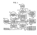
- Fig. 1 The diagram of Fig. 1 is similar to Fig. 6 of U.S. Patent No. 4,349,000, in order to show context for Fig. 2 circuitry of the invention, the same being shown in Fig. 1 as signal-processing circuitry 10, operative upon tachometer voltage E T and being modulated by the output signal of a differential-pressure transducer 11 connected for response to the instantaneous drop in pressure across the engine throttle 12.
- This pressure drop will be understood to be a function of the negative-pressure or vacuum condition at the intake manifold of the engine; specifically, at full throttle and maximum speed, the pressure drop to zero or near zero, and the pressure drop is greatest at minimum throttle (and therefore at minimum engine speed).
- the modulated-signal output of the signal-processing circuitry 10 is supplied as a d-c analog voltage for multiplication at 13 with a voltage E M , and the product of this multiplication is a fuel-control voltage E MF : in other words, the elements 10, 11, 12 and 13 of Fig. 1 replace the potentiometer 53 and throttle control 54 of Fig. 6 of U.S. Patent No. 4,349,000.
- the expression "Throttle-position" at multiplier 13 in Fig. 1 will be understood to express the effective accomplishment of mechanically tracking throttle position, without having resort to any mechanical motion-tracking to achieve this result.
- the circuit of Fig. 1 is shown in application to the development of fuel-injection voltage pulses for operation of a two-cycle V-6 engine described in detail in U.S. Patent No. 4,349,000, and said circuit operates on various input parameters, in the form of analog voltages which reflect air-mass flow for the current engine speed, a correction being made for volumetric efficiency of the particular engine, to arrive at a modulating-voltage output E MoD in a line 15 to each of two like square-wave pulses generators 16-17.
- the square-wave output at 18 will be of predetermined duration, and the square-wave output at 19 will be of duration identical to that in line 18, it being understood that the predetermined duration is always a function of instantaneous engine-operating conditions.
- a first electrical sensor 20 of manifold absolute pressure is a source of first voltage E MAP which is linearly related to such pressure
- a second electrical sensor 21 of manifold absolute temperature may be a thermistor which provides a voltage linearly related to such temperature, through a resistor network 22.
- the voltage E MAP is divided by the network 22 to produce an output voltage E M , which is a linear function of instantaneous air-mass or density at inlet of air to the engine.
- a first amplifier A provides the output voltage E M which is one of the inputs to multiplier 13.
- the voltage product E MF , of multiplier 13 reflects instantaneous air-mass flow for the instantaneous effective throttle (12) setting and engine speed, and a second amplifier A 2 provides a corresponding output voltage E MF for application to one of the voltage-multiplier inputs of a modulator 25, which is the source of E MOD .
- the other voltage-multiplier input of modulator 25 receives an input voltage E E which is a function of engine speed (tachometer 26) and volumetric efficiency (network 27).
- VDD voltage regulator
- Fig. 2 wherein "VDD” will be understood to mean connection to the engine's regulated power supply (not shown in detail), about 8 volts; and legend indicates use of the engine alternator (not shown) to provide a tachometer function by reason of its frequency dependence upon engine rpm.
- This alternator voltage enters the signal-processing circuitry at a filter R 1 ⁇ C 1 , so that the alternator output frequency in the voltage across an amplifier-input resistor R 2 can be clean, i.e., free of high-frequency (rf) noise.
- High-gain amplification via a transistor Q 1 converts the sinusoidal output of the alternator to a square-wave voltage (at alternator frequency) across a resistor R 3 .
- a capacitor C 2 differentiates the square-wave voltage, producing a series of sharply defined positive pulses; after diode clipping at D 2 , only the negative voltage pulses remain across a resistor R 4 , for recycle-triggering of an integrated circuit IC, which may be of the type-555 variety, connected for operation as a monostable multivibrator. Circuit constants are suitably selected so that such triggering results from cut-off of each rising multivibrator voltage at about the 2/3 VDD point.
- a differential-pressure transducer 30 may include a strain-gage bridge 31, for developing an electrical response to the instantaneous pressure drop across the throttle 12 of Fig. 1. As shown, this electrical response is processed by operational amplifiers 32-33 and associated resistors R 16 , R 17 (as trimmed at R 27 ) and R 18 , to deliver a multivibrator-modulating voltage in the range from zero or near-zero, to six volts; this modulating voltage appears at the connection 34 between resistors R 7 ⁇ R 8 and is determinative of the level at which each recycled multivibrator-voltage rise commences.
- the multivibrator output appears across a resistor R s as a succession of square-wave voltage pulses at tachometer frequency and with a duty cycle which is an inverse function of the voltage derived from the pressure drop across throttle 12.
- Filter action via elements R 6 ⁇ C 4 smooths this pulsing voltage to a d-c voltage at the positive (+) input of an operational amplifier 35, connected as a buffer, for isolation of its d-c voltage output across a resistor R9.
- the smoothed and buffered quotient voltage which appears across resistor Rg contains all the effective "throttle-positioning" data needed for replacement of the mechanically tracking throttle potentiometer 11 of Fig. 1 of U.S. patent No. 4,349,000, the only remaining problem being that of effectively multiplying the voltage E M by this quotient voltage to achieve the voltage E MF needed by the control unit 25.
- the effective multiplication is achieved by connecting the voltage E M across a switching transistor Q 2 and its load resistor R, 4 , and by using the quotient voltage value to control the duty cycle of switch Q 2 ; the resulting time-modulated output is smoothed by filter means R 13 ⁇ C 6 to yield the d-c output voltage E MF , needed by the control unit.
- a second integrated circuit IC 2 which may also be the same type 555 as IC 1 , is connected with associated circuitry as a sawtooth generator 35, operating at a frequency of about 1000 Hz and supplying its sawtooth-voltage output to the positive (+) input of an operational amplifier 36.
- the latter is connected as a comparator, with quotient voltage applied to the negative (-) input.
- the sawtooth voltage thus recurrently scans the current level of quotient voltage to determine the on/off duty cycle of the switching transistor Q 2 .
- the quotient voltage at Rg is applied via a coupling resistor R 10 to the connection point 37 of resistors R 11 -R 12 which divide the power-supply voltage VDD.
- the four operational amplifiers (32, 33, 35, 56) are suggested by legend to be individual quarter segments of a single integrated circuit component IC 2 , variously connected as above described.
Landscapes
- Engineering & Computer Science (AREA)
- Computer Hardware Design (AREA)
- Microelectronics & Electronic Packaging (AREA)
- Chemical & Material Sciences (AREA)
- Combustion & Propulsion (AREA)
- Mechanical Engineering (AREA)
- General Engineering & Computer Science (AREA)
- Electrical Control Of Air Or Fuel Supplied To Internal-Combustion Engine (AREA)
- Combined Controls Of Internal Combustion Engines (AREA)
- Fuel-Injection Apparatus (AREA)
Claims (3)
Priority Applications (1)
| Application Number | Priority Date | Filing Date | Title |
|---|---|---|---|
| AT88900903T ATE58206T1 (de) | 1986-12-01 | 1987-11-24 | Drosselklappen-stellungssensor fuer elektronisches kraftstoffeinspritzungssystem. |
Applications Claiming Priority (2)
| Application Number | Priority Date | Filing Date | Title |
|---|---|---|---|
| US93659286A | 1986-12-01 | 1986-12-01 | |
| US936592 | 1986-12-01 |
Publications (2)
| Publication Number | Publication Date |
|---|---|
| EP0334894A1 EP0334894A1 (de) | 1989-10-04 |
| EP0334894B1 true EP0334894B1 (de) | 1990-11-07 |
Family
ID=25468864
Family Applications (1)
| Application Number | Title | Priority Date | Filing Date |
|---|---|---|---|
| EP88900903A Expired - Lifetime EP0334894B1 (de) | 1986-12-01 | 1987-11-24 | Drosselklappen-stellungssensor für elektronisches kraftstoffeinspritzungssystem |
Country Status (7)
| Country | Link |
|---|---|
| EP (1) | EP0334894B1 (de) |
| JP (1) | JPH02501399A (de) |
| AT (1) | ATE58206T1 (de) |
| BR (1) | BR8707900A (de) |
| CA (1) | CA1286752C (de) |
| DE (1) | DE3766112D1 (de) |
| WO (1) | WO1988004361A2 (de) |
Family Cites Families (4)
| Publication number | Priority date | Publication date | Assignee | Title |
|---|---|---|---|---|
| US3888458A (en) * | 1972-08-09 | 1975-06-10 | Gen Motors Corp | Mass flow air meter |
| FR2406727A1 (fr) * | 1977-10-21 | 1979-05-18 | Herbault Patrick | Procede permettant la simplification des systemes d'injection electronique de carburant |
| JPS5820948A (ja) * | 1981-07-29 | 1983-02-07 | Mikuni Kogyo Co Ltd | 内燃機関の燃料供給装置 |
| JPS60178948A (ja) * | 1984-02-24 | 1985-09-12 | Honda Motor Co Ltd | 内燃エンジンの電子燃料供給制御装置の異常検出表示装置 |
-
1987
- 1987-11-24 AT AT88900903T patent/ATE58206T1/de not_active IP Right Cessation
- 1987-11-24 DE DE8888900903T patent/DE3766112D1/de not_active Expired - Fee Related
- 1987-11-24 BR BR8707900A patent/BR8707900A/pt unknown
- 1987-11-24 JP JP88501064A patent/JPH02501399A/ja active Pending
- 1987-11-24 EP EP88900903A patent/EP0334894B1/de not_active Expired - Lifetime
- 1987-11-24 WO PCT/US1987/003121 patent/WO1988004361A2/en not_active Ceased
- 1987-11-30 CA CA000553166A patent/CA1286752C/en not_active Expired - Fee Related
Non-Patent Citations (1)
| Title |
|---|
| Patent Abstracts of Japan, volume 9, no. 316 (M-438)(2039), 12 December 1985, & JP, A, 60151445 (Nissan Hidosha K.K.) 9 August 1985 * |
Also Published As
| Publication number | Publication date |
|---|---|
| ATE58206T1 (de) | 1990-11-15 |
| EP0334894A1 (de) | 1989-10-04 |
| CA1286752C (en) | 1991-07-23 |
| BR8707900A (pt) | 1989-10-31 |
| JPH02501399A (ja) | 1990-05-17 |
| DE3766112D1 (de) | 1990-12-13 |
| WO1988004361A3 (en) | 1988-07-14 |
| WO1988004361A2 (en) | 1988-06-16 |
Similar Documents
| Publication | Publication Date | Title |
|---|---|---|
| US4048964A (en) | Fuel metering apparatus and method | |
| US3935851A (en) | Fuel metering system for spark ignition engines | |
| CA1067178A (en) | Fuel control system having an auxiliary circuit for correcting the signals generated by the pressure sensor during transient operating conditions | |
| US3332406A (en) | Electronic speed control system | |
| EP0719929A3 (de) | Regelungssystem für die Brennstoffdosierung eines Innenverbrennungsmotors | |
| BR9205424A (pt) | Sistema de gerenciamento de motor | |
| US3796198A (en) | Fuel injection arrangement | |
| US4058089A (en) | Electrically controlled fuel injection system | |
| EP0132985B1 (de) | Steuereinrichtung für eine Brennkraftmaschine | |
| GB2120390A (en) | Measuring air flow | |
| US4915072A (en) | Electronic governor interface module | |
| US3911883A (en) | Fuel systems for engines | |
| US4739742A (en) | Throttle-position sensor for an electronic fuel-injection system | |
| GB2047440A (en) | Exhaust gas recirculation control system | |
| EP0334894B1 (de) | Drosselklappen-stellungssensor für elektronisches kraftstoffeinspritzungssystem | |
| GB2061531A (en) | Inductive measuring system | |
| CA1189591A (en) | Atomization compensation for electronic fuel injection | |
| US4523572A (en) | Fuel flow monitor for an electronic fuel injection circuit | |
| GB1273107A (en) | Improvements in and relating to fuel injection governors for diesel internal combustion engines and particularly to electrical protection circuits for such governors | |
| US4501247A (en) | Electronically controllable and regulatable fuel metering system of an internal combustion engine | |
| EP0719927A3 (de) | Regelungssystem für die Brennstoffdosierung eines Innenverbrennungsmotors | |
| US4070609A (en) | Automatic control system | |
| JPS58206836A (ja) | 電子制御システム | |
| EP0082785A3 (de) | Brennstoffregelsystem für Gasturbinen | |
| JPS603953Y2 (ja) | 電子制御燃料噴射装置 |
Legal Events
| Date | Code | Title | Description |
|---|---|---|---|
| PUAI | Public reference made under article 153(3) epc to a published international application that has entered the european phase |
Free format text: ORIGINAL CODE: 0009012 |
|
| 17P | Request for examination filed |
Effective date: 19890531 |
|
| AK | Designated contracting states |
Kind code of ref document: A1 Designated state(s): AT BE CH DE FR GB IT LI LU NL SE |
|
| 17Q | First examination report despatched |
Effective date: 19900221 |
|
| GRAA | (expected) grant |
Free format text: ORIGINAL CODE: 0009210 |
|
| AK | Designated contracting states |
Kind code of ref document: B1 Designated state(s): AT BE CH DE FR GB IT LI LU NL SE |
|
| PG25 | Lapsed in a contracting state [announced via postgrant information from national office to epo] |
Ref country code: IT Free format text: LAPSE BECAUSE OF FAILURE TO SUBMIT A TRANSLATION OF THE DESCRIPTION OR TO PAY THE FEE WITHIN THE PRE;WARNING: LAPSES OF ITALIAN PATENTS WITH EFFECTIVE DATE BEFORE 2007 MAY HAVE OCCURRED AT ANY TIME BEFORE 2007. THE CORRECT EFFECTIVE DATE MAY BE DIFFERENT FROM THE ONE RECORDED.SCRIBED TIME-LIMIT Effective date: 19901107 Ref country code: CH Effective date: 19901107 Ref country code: NL Effective date: 19901107 Ref country code: SE Effective date: 19901107 Ref country code: LI Effective date: 19901107 Ref country code: FR Effective date: 19901107 Ref country code: AT Effective date: 19901107 Ref country code: BE Effective date: 19901107 |
|
| REF | Corresponds to: |
Ref document number: 58206 Country of ref document: AT Date of ref document: 19901115 Kind code of ref document: T |
|
| PG25 | Lapsed in a contracting state [announced via postgrant information from national office to epo] |
Ref country code: LU Free format text: LAPSE BECAUSE OF NON-PAYMENT OF DUE FEES Effective date: 19901130 |
|
| REF | Corresponds to: |
Ref document number: 3766112 Country of ref document: DE Date of ref document: 19901213 |
|
| REG | Reference to a national code |
Ref country code: CH Ref legal event code: PL |
|
| EN | Fr: translation not filed | ||
| NLV1 | Nl: lapsed or annulled due to failure to fulfill the requirements of art. 29p and 29m of the patents act | ||
| PLBE | No opposition filed within time limit |
Free format text: ORIGINAL CODE: 0009261 |
|
| STAA | Information on the status of an ep patent application or granted ep patent |
Free format text: STATUS: NO OPPOSITION FILED WITHIN TIME LIMIT |
|
| PGFP | Annual fee paid to national office [announced via postgrant information from national office to epo] |
Ref country code: DE Payment date: 19911025 Year of fee payment: 5 |
|
| PGFP | Annual fee paid to national office [announced via postgrant information from national office to epo] |
Ref country code: GB Payment date: 19911028 Year of fee payment: 5 |
|
| 26N | No opposition filed | ||
| PG25 | Lapsed in a contracting state [announced via postgrant information from national office to epo] |
Ref country code: GB Effective date: 19921124 |
|
| GBPC | Gb: european patent ceased through non-payment of renewal fee |
Effective date: 19921124 |
|
| PG25 | Lapsed in a contracting state [announced via postgrant information from national office to epo] |
Ref country code: DE Effective date: 19930803 |