EP0334817A1 - A radiator for motor vehicles - Google Patents
A radiator for motor vehicles Download PDFInfo
- Publication number
- EP0334817A1 EP0334817A1 EP89830099A EP89830099A EP0334817A1 EP 0334817 A1 EP0334817 A1 EP 0334817A1 EP 89830099 A EP89830099 A EP 89830099A EP 89830099 A EP89830099 A EP 89830099A EP 0334817 A1 EP0334817 A1 EP 0334817A1
- Authority
- EP
- European Patent Office
- Prior art keywords
- gasket
- end plate
- tubes
- holes
- cover
- Prior art date
- Legal status (The legal status is an assumption and is not a legal conclusion. Google has not performed a legal analysis and makes no representation as to the accuracy of the status listed.)
- Withdrawn
Links
Images
Classifications
-
- F—MECHANICAL ENGINEERING; LIGHTING; HEATING; WEAPONS; BLASTING
- F28—HEAT EXCHANGE IN GENERAL
- F28F—DETAILS OF HEAT-EXCHANGE AND HEAT-TRANSFER APPARATUS, OF GENERAL APPLICATION
- F28F21/00—Constructions of heat-exchange apparatus characterised by the selection of particular materials
- F28F21/06—Constructions of heat-exchange apparatus characterised by the selection of particular materials of plastics material
- F28F21/067—Details
-
- F—MECHANICAL ENGINEERING; LIGHTING; HEATING; WEAPONS; BLASTING
- F16—ENGINEERING ELEMENTS AND UNITS; GENERAL MEASURES FOR PRODUCING AND MAINTAINING EFFECTIVE FUNCTIONING OF MACHINES OR INSTALLATIONS; THERMAL INSULATION IN GENERAL
- F16L—PIPES; JOINTS OR FITTINGS FOR PIPES; SUPPORTS FOR PIPES, CABLES OR PROTECTIVE TUBING; MEANS FOR THERMAL INSULATION IN GENERAL
- F16L41/00—Branching pipes; Joining pipes to walls
- F16L41/001—Branching pipes; Joining pipes to walls the wall being a pipe plate
-
- F—MECHANICAL ENGINEERING; LIGHTING; HEATING; WEAPONS; BLASTING
- F28—HEAT EXCHANGE IN GENERAL
- F28F—DETAILS OF HEAT-EXCHANGE AND HEAT-TRANSFER APPARATUS, OF GENERAL APPLICATION
- F28F9/00—Casings; Header boxes; Auxiliary supports for elements; Auxiliary members within casings
- F28F9/02—Header boxes; End plates
- F28F9/0219—Arrangements for sealing end plates into casing or header box; Header box sub-elements
- F28F9/0224—Header boxes formed by sealing end plates into covers
- F28F9/0226—Header boxes formed by sealing end plates into covers with resilient gaskets
-
- F—MECHANICAL ENGINEERING; LIGHTING; HEATING; WEAPONS; BLASTING
- F28—HEAT EXCHANGE IN GENERAL
- F28F—DETAILS OF HEAT-EXCHANGE AND HEAT-TRANSFER APPARATUS, OF GENERAL APPLICATION
- F28F9/00—Casings; Header boxes; Auxiliary supports for elements; Auxiliary members within casings
- F28F9/02—Header boxes; End plates
- F28F9/04—Arrangements for sealing elements into header boxes or end plates
- F28F9/06—Arrangements for sealing elements into header boxes or end plates by dismountable joints
- F28F9/14—Arrangements for sealing elements into header boxes or end plates by dismountable joints by force-joining
Definitions
- the present invention relates to a heat exchanger, particularly for motor vehicle air-conditioning systems, of the type comprising a plurality of tubes, at least one end plate having a plurality of holes provided with collars in which the ends of the tubes are engaged, a cover fixed to the end plate so as to define a header chamber, gasket having a plurality of holes provided with thickened edges, the thickened edges being interposed between the tubes and the collars of the end plate, and a gasket-pressing plate situated on the side of the gasket which faces the header chamber and also having a plurality of holes in which the ends of the tubes of the exchanger are housed.
- the object of the present invention is to provide a heat exchanger which can be assembled quickly and easily and enables a seal to be effected between the tubes and the header, which does not depend on the sectional shapes of the tubes.
- this object is achieved by virtue of the fact that the cover has engagement means which, when the cover is fitted to the end plate, are adapted to cooperate with the gasket-pressing plate so as to compress it and thus press the thickened edges of the holes of the gasket against the outer surfaces of the tubes to effect a seal between the tubes and the end plate.
- tubes having circular, oval or elliptical sections can be used in a heat exchanger according to the invention.
- the cover and the end plate are preferably fitted together by vibration, ultrasonic or hot-blade face welding.
- a tube of a heat exchanger used, for example, in a motor vehicle air-conditioning system is indicated 10 and is mounted in a corresponding hole 12 in a plastics end plate 14.
- the end plate 14 has substantially frusto-conical collars 14a whose function will become clear from the following description.
- the tubes 10 are brought into the holes 12 so as to ensure that the joint has a predetermined mechanical strength.
- a cover 16 is joined to the end plate 14 by ultrasonic, vibration or hot-blade welding and defines a header chamber A divided by a vertical wall 18. If the header chamber A is not to be divided, rods may be used instead of the wall 18 to stiffen the header.
- the cover 16 has a side wall 16a which, in correspondence with an internal face, is provided with an annular shoulder 20 for cooperating with a peripheral edge 22a of a gasket-pressing plate 22 provided with holes 23 in which the ends 10a of the tubes 10 are housed.
- a gasket 24 of elastomeric material is interposed between the gasket-pressing plate 22 and the end plate 14 and is provided with holes 26 in correspondence with the ends 10a of the tubes 10.
- the gasket 24 has thickened edges 24a in correspondence with the holes 26.
- these thickened edges 24a are pressed into the space between the collar 14a and the respective tube 10 by means of the gasket-pressing plate 22 which is pushed by the annular shoulder 20 and by the wall 18.
- the deformation of the edge 24a therefore ensures a seal between the tube and the header, as well as "mechanical" fixing between the tube and the header.
- the frusto-conical collars may be formed at the edges 22b of the gasket-pressing plate 22 around the holes 23 ( Figure 4), instead of in the end plate.
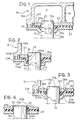
- Figure 2 shows a second embodiment of the invention.
- the same reference numerals as in Figure 1 have been used for details which are substantially identical, whilst the same reference numerals as in Figure 1, but increased by 100, have been used for details which are similar.
- the end plate 114 has collars 114a with L-shaped sections so as to define an annular chamber B beside the end 10a of the tube 10.
- the gasket-pressing plate 122 has tubular portions 30 projecting from the plane of the plate so as to slide substantially telescopically relative to the collar 114a and compress the thickened edges 124a of the gasket 124. The deformation of the gasket is thus more easily controllable.
- the pressure between the gasket-pressing plate 222 and the end plate 214 is achieved by virtue of the engagement of pins 32 formed integrally with the plate 214 in corresponding auxiliary holes 34 formed in the gasket-pressing plate 222.
- the cooperation between the plate 222 and the pins 32 is achieved, for example, by upsetting the free ends 34a of the pins 34; if the end plate 214 is made of plastics, the ends 34a can be subjected to plastic deformation, for example, by means of ultrasound.
- the deformation of the thickened edges 224a of the gasket 224 is thus achieved independently of the fitting together of the cover 16 and the end plate 214.
Abstract
A radiator for motor vehicle air-conditioning systems has a system for effecting a seal between its tubes (10) and tube plates (14), including a gasket (24) having holes (26) with thickened edges (24a) which are adapted to be compressed into suitable frusto-conical collars (14a) of the tube plate (14) by means of a gasket-pressing plate (22). The gasket-pressing plate (22) is kept in the operative position by an internal annular shoulder (20) provided on the side wall (16a) of the header (16) fixed to the respective tube plate (14).
Description
- The present invention relates to a heat exchanger, particularly for motor vehicle air-conditioning systems, of the type comprising a plurality of tubes, at least one end plate having a plurality of holes provided with collars in which the ends of the tubes are engaged, a cover fixed to the end plate so as to define a header chamber, gasket having a plurality of holes provided with thickened edges, the thickened edges being interposed between the tubes and the collars of the end plate, and a gasket-pressing plate situated on the side of the gasket which faces the header chamber and also having a plurality of holes in which the ends of the tubes of the exchanger are housed.
- The object of the present invention is to provide a heat exchanger which can be assembled quickly and easily and enables a seal to be effected between the tubes and the header, which does not depend on the sectional shapes of the tubes.
- According to the invention, this object is achieved by virtue of the fact that the cover has engagement means which, when the cover is fitted to the end plate, are adapted to cooperate with the gasket-pressing plate so as to compress it and thus press the thickened edges of the holes of the gasket against the outer surfaces of the tubes to effect a seal between the tubes and the end plate.
- The operation of expanding the ends of the tubes over the gasket-pressing plate can thus be avoided, since the "squashing" of the gasket is achieved by the engagement between the cover and the end plate when they are fitted together. Moreover, tubes having circular, oval or elliptical sections can be used in a heat exchanger according to the invention.
- In an exchanger in which the end plate and the cover are made of plastics, the cover and the end plate are preferably fitted together by vibration, ultrasonic or hot-blade face welding.
- The production cycle for the assembly of the whole exchanger thus takes place in a considerably shorter time with consequent production cost advantages.
- Further characteristics and advantages of an exchanger according to the present invention will become clear from the detailed description which follows with reference to the appended drawings, provided by way of non-limiting example, in which:
- Figure 1 is a schematic section of a portion of a water-air heat exchanger according to the invention,
- Figure 2 is a view similar to Figure 1 and shows a second embodiment of the invention,
- Figure 3 is a view similar to Figures 1-2 and shows a third embodiment of the invention, and
- Figure 4 is a detail of a variant of the exchanger of Figure 1.
- With reference to the drawings, a tube of a heat exchanger used, for example, in a motor vehicle air-conditioning system is indicated 10 and is mounted in a
corresponding hole 12 in aplastics end plate 14. In correspondence with theholes 12, theend plate 14 has substantially frusto-conical collars 14a whose function will become clear from the following description. During the expansion of the radiant pack, thetubes 10 are brought into theholes 12 so as to ensure that the joint has a predetermined mechanical strength. - A
cover 16 is joined to theend plate 14 by ultrasonic, vibration or hot-blade welding and defines a header chamber A divided by avertical wall 18. If the header chamber A is not to be divided, rods may be used instead of thewall 18 to stiffen the header. Thecover 16 has aside wall 16a which, in correspondence with an internal face, is provided with anannular shoulder 20 for cooperating with aperipheral edge 22a of a gasket-pressingplate 22 provided withholes 23 in which theends 10a of thetubes 10 are housed. Agasket 24 of elastomeric material is interposed between the gasket-pressingplate 22 and theend plate 14 and is provided withholes 26 in correspondence with theends 10a of thetubes 10. Moreover, thegasket 24 has thickenededges 24a in correspondence with theholes 26. In the operative configuration illustrated in Figure 1, these thickenededges 24a are pressed into the space between thecollar 14a and therespective tube 10 by means of the gasket-pressing plate 22 which is pushed by theannular shoulder 20 and by thewall 18. The deformation of theedge 24a therefore ensures a seal between the tube and the header, as well as "mechanical" fixing between the tube and the header. - The frusto-conical collars may be formed at the
edges 22b of the gasket-pressing plate 22 around the holes 23 (Figure 4), instead of in the end plate. - Figure 2 shows a second embodiment of the invention. In Figure 2 the same reference numerals as in Figure 1 have been used for details which are substantially identical, whilst the same reference numerals as in Figure 1, but increased by 100, have been used for details which are similar.
- The
end plate 114 has collars 114a with L-shaped sections so as to define an annular chamber B beside theend 10a of thetube 10. In correspondence with theholes 23, the gasket-pressing plate 122 hastubular portions 30 projecting from the plane of the plate so as to slide substantially telescopically relative to the collar 114a and compress the thickenededges 124a of the gasket 124. The deformation of the gasket is thus more easily controllable. - In Figure 3, which shows a third embodiment of the invention, the same reference numerals as in Figure 1 has been used for substantially identical details, whilst the same reference numerals as in Figure 1, but increased by 200, have been used for similar details.
- In the sealing system shown in Figure 3, the pressure between the gasket-pressing
plate 222 and theend plate 214 is achieved by virtue of the engagement ofpins 32 formed integrally with theplate 214 in correspondingauxiliary holes 34 formed in the gasket-pressing plate 222. The cooperation between theplate 222 and thepins 32 is achieved, for example, by upsetting thefree ends 34a of thepins 34; if theend plate 214 is made of plastics, theends 34a can be subjected to plastic deformation, for example, by means of ultrasound. The deformation of the thickened edges 224a of thegasket 224 is thus achieved independently of the fitting together of thecover 16 and theend plate 214.
Claims (5)
1. A heat exchanger, particularly for motor vehicle air-conditioning systems, of the type comprising:
- a plurality of tubes (10),
- at least one end plate (14, 114) having a plurality of holes (12, 112) provided with collars (14a, 114a) in which the ends (10a) of the tubes (10) are engaged,
- a cover (16) fixed to the end plate (14, 114) so as to define a header chamber (A),
- a gasket (24, 124) having a plurality of holes (26) with thickened edges (24a, 124a), the thickened edges being interposed between the tubes and the collars of the end plate, and
- a gasket-pressing plate (22, 122) situated on the side of the gasket which faces the header chamber (A) and also having a plurality of holes in which the ends of the tubes of the exchanger are housed,
characterised in that the cover (16) has engagement means (20, 18) which, when the cover is fitted to the end plate (14, 114), are adapted to cooperate with the gasket-pressing plate (22, 122) so as to compress it and thus press the thickened edges (24a, 124a) of the holes (26) of the gasket (24, 124) against the outer surfaces of the tubes (10) to effect a seal between the tubes and the end plate.
2. An exchanger according to Claim 1, in which the end plate (14, 114) and the cover (16) are made of plastics material, characterised in that the cover and the end plate are fitted together by vibration, ultrasonic or hot-blade face welding.
3. An exchanger according to Claim 1, charcterised in that the engagement means comprise an annular shoulder (20) in correspondence with side walls (16a) of the cover (16) for cooperating with a peripheral edge (22a, 122a) of the gasket-pressing plate (22, 122).
4. An exchanger according to any one of the preceding claims, characterised in that the collars (114a) of the end plate (114) have walls with L-shaped sections, and in that the gasket-pressing plate (122) has edges which are in correspondence with the respective holes (23) and are bent into L-shapes substantially corresponding to those of the collars (114a).
5. A heat exchanger, particularly for motor vehicle air-conditioning systems of the type comprising a plurality of tubes, at least one plastics end plate having a plurality of holes with collars in which the ends of the tubes are engaged, a plastics cover fixed to the end plate so as to define a header chamber, a gasket having a plurality of holes provided with thickened edges, the thickened edges being interposed between the tubes and the collars of the end plate, a gasket-pressing plate situated on the side of the gasket which faces the header chamber and also having a plurality of holes in which the ends of the tubes of the exchanger are housed, characterised in that the gasket-pressing plate (222) has a plurality of auxiliary holes (34) for the passage of fixing pins (32) integral with the end plate (214), the pins being upset by plastic deformation onto the gasket-pressing plate (222) so as to compress the gasket (224).
Applications Claiming Priority (2)
| Application Number | Priority Date | Filing Date | Title |
|---|---|---|---|
| IT67263/88A IT1219145B (en) | 1988-03-24 | 1988-03-24 | MOTOR VEHICLE RADIATOR |
| IT6726388 | 1988-03-24 |
Publications (1)
| Publication Number | Publication Date |
|---|---|
| EP0334817A1 true EP0334817A1 (en) | 1989-09-27 |
Family
ID=11300960
Family Applications (1)
| Application Number | Title | Priority Date | Filing Date |
|---|---|---|---|
| EP89830099A Withdrawn EP0334817A1 (en) | 1988-03-24 | 1989-03-07 | A radiator for motor vehicles |
Country Status (2)
| Country | Link |
|---|---|
| EP (1) | EP0334817A1 (en) |
| IT (1) | IT1219145B (en) |
Cited By (9)
| Publication number | Priority date | Publication date | Assignee | Title |
|---|---|---|---|---|
| DE4041671A1 (en) * | 1990-12-22 | 1992-06-25 | Behr Gmbh & Co | Heat exchanger unit - has tube ends widened, extending over tube floor, with sealing mat between water tank and tube floor |
| EP0736717A1 (en) * | 1995-04-07 | 1996-10-09 | Regie Nationale Des Usines Renault S.A. | Sealing connecting device for a hydraulic circuit |
| FR2783907A1 (en) * | 1998-09-25 | 2000-03-31 | Valeo Thermique Moteur Sa | REDUCED HEAT EXCHANGER, PARTICULARLY FOR A MOTOR VEHICLE |
| FR2803378A1 (en) * | 1999-12-29 | 2001-07-06 | Valeo Climatisation | HEAT EXCHANGER WITH MULTI-CHANNEL TUBES, ESPECIALLY FOR A MOTOR VEHICLE |
| EP1273864A3 (en) * | 2001-07-05 | 2003-06-11 | Modine Manufacturing Company | Heat exchanger |
| WO2013076567A3 (en) * | 2011-11-25 | 2015-02-19 | Pilosio Bruno | Perfected heat exchanger and production method |
| CN105202963A (en) * | 2015-09-29 | 2015-12-30 | 茂名重力石化机械制造有限公司 | Non-welding forced sealing structure for heat exchange tube and tube plate |
| KR20160145137A (en) * | 2014-05-05 | 2016-12-19 | 발레오 시스템므 떼르미끄 | Header for a heat exchanger of a motor vehicle |
| CN111998718A (en) * | 2020-09-10 | 2020-11-27 | 张春丽 | Double-tube plate sealing device of heat exchanger |
Citations (7)
| Publication number | Priority date | Publication date | Assignee | Title |
|---|---|---|---|---|
| GB315934A (en) * | 1928-05-05 | 1929-07-25 | Henry Kirk | Improvements in and connected with tube radiators |
| GB431863A (en) * | 1934-01-15 | 1935-07-15 | Herbert Houlding | Improvements in or relating to radiators and like tubes, and in joints therefor |
| GB559981A (en) * | 1942-10-22 | 1944-03-14 | James Chew And Company Ltd | Improvements relating to tube joints |
| DE2004860A1 (en) * | 1969-02-03 | 1970-08-06 | S.A. des Usines Chausson, Asnieres, Seine (Frankreich) | Heat exchangers for heating or cooling a fluid, in particular for vehicles |
| FR2214875A1 (en) * | 1973-01-20 | 1974-08-19 | Sueddeutsche Kuehler Behr | |
| DE2930577A1 (en) * | 1979-07-27 | 1981-02-12 | Wiessner Gmbh | Heat exchanger for heat recovery from exhaust gas - using bundle of glass tubes supported in tube plate and sealed with O=rings |
| FR2512941A1 (en) * | 1981-09-14 | 1983-03-18 | Valeo | PARALLEL TUBE BEAM HEAT EXCHANGER AND METHOD OF ASSEMBLING ITS CONSTITUENT ELEMENTS |
-
1988
- 1988-03-24 IT IT67263/88A patent/IT1219145B/en active
-
1989
- 1989-03-07 EP EP89830099A patent/EP0334817A1/en not_active Withdrawn
Patent Citations (7)
| Publication number | Priority date | Publication date | Assignee | Title |
|---|---|---|---|---|
| GB315934A (en) * | 1928-05-05 | 1929-07-25 | Henry Kirk | Improvements in and connected with tube radiators |
| GB431863A (en) * | 1934-01-15 | 1935-07-15 | Herbert Houlding | Improvements in or relating to radiators and like tubes, and in joints therefor |
| GB559981A (en) * | 1942-10-22 | 1944-03-14 | James Chew And Company Ltd | Improvements relating to tube joints |
| DE2004860A1 (en) * | 1969-02-03 | 1970-08-06 | S.A. des Usines Chausson, Asnieres, Seine (Frankreich) | Heat exchangers for heating or cooling a fluid, in particular for vehicles |
| FR2214875A1 (en) * | 1973-01-20 | 1974-08-19 | Sueddeutsche Kuehler Behr | |
| DE2930577A1 (en) * | 1979-07-27 | 1981-02-12 | Wiessner Gmbh | Heat exchanger for heat recovery from exhaust gas - using bundle of glass tubes supported in tube plate and sealed with O=rings |
| FR2512941A1 (en) * | 1981-09-14 | 1983-03-18 | Valeo | PARALLEL TUBE BEAM HEAT EXCHANGER AND METHOD OF ASSEMBLING ITS CONSTITUENT ELEMENTS |
Cited By (19)
| Publication number | Priority date | Publication date | Assignee | Title |
|---|---|---|---|---|
| DE4041671A1 (en) * | 1990-12-22 | 1992-06-25 | Behr Gmbh & Co | Heat exchanger unit - has tube ends widened, extending over tube floor, with sealing mat between water tank and tube floor |
| EP0736717A1 (en) * | 1995-04-07 | 1996-10-09 | Regie Nationale Des Usines Renault S.A. | Sealing connecting device for a hydraulic circuit |
| FR2732744A1 (en) * | 1995-04-07 | 1996-10-11 | Renault | WATERPROOF CONNECTION DEVICE FOR HYDRAULIC CIRCUIT |
| US6296051B1 (en) | 1998-09-25 | 2001-10-02 | Valeo Termique Moteur | Heat exchanger with reduced space requirement, in particular for motor vehicle |
| FR2783907A1 (en) * | 1998-09-25 | 2000-03-31 | Valeo Thermique Moteur Sa | REDUCED HEAT EXCHANGER, PARTICULARLY FOR A MOTOR VEHICLE |
| WO2000019163A1 (en) * | 1998-09-25 | 2000-04-06 | Valeo Thermique Moteur | Heat exchanger with reduced space requirement, in particular for motor vehicle |
| WO2001050080A3 (en) * | 1999-12-29 | 2002-01-31 | Valeo Climatisation | Multichannel tube heat exchanger |
| WO2001050080A2 (en) * | 1999-12-29 | 2001-07-12 | Valeo Climatisation | Multichannel tube heat exchanger |
| FR2803378A1 (en) * | 1999-12-29 | 2001-07-06 | Valeo Climatisation | HEAT EXCHANGER WITH MULTI-CHANNEL TUBES, ESPECIALLY FOR A MOTOR VEHICLE |
| JP2003519356A (en) * | 1999-12-29 | 2003-06-17 | ヴァレオ クリマチザション | Heat exchanger |
| JP4869530B2 (en) * | 1999-12-29 | 2012-02-08 | ヴァレオ クリマチザション | Heat exchanger |
| EP1273864A3 (en) * | 2001-07-05 | 2003-06-11 | Modine Manufacturing Company | Heat exchanger |
| WO2013076567A3 (en) * | 2011-11-25 | 2015-02-19 | Pilosio Bruno | Perfected heat exchanger and production method |
| KR20160145137A (en) * | 2014-05-05 | 2016-12-19 | 발레오 시스템므 떼르미끄 | Header for a heat exchanger of a motor vehicle |
| JP2017515086A (en) * | 2014-05-05 | 2017-06-08 | ヴァレオ システム テルミク | Automotive heat exchanger header |
| US10180290B2 (en) | 2014-05-05 | 2019-01-15 | Valeo Systemes Thermiques | Header for a heat exchanger of a motor vehicle |
| CN105202963A (en) * | 2015-09-29 | 2015-12-30 | 茂名重力石化机械制造有限公司 | Non-welding forced sealing structure for heat exchange tube and tube plate |
| CN105202963B (en) * | 2015-09-29 | 2017-12-08 | 茂名重力石化装备股份公司 | A kind of non-solder forced sealing structure of exchanger tubes and tubesheets |
| CN111998718A (en) * | 2020-09-10 | 2020-11-27 | 张春丽 | Double-tube plate sealing device of heat exchanger |
Also Published As
| Publication number | Publication date |
|---|---|
| IT8867263A0 (en) | 1988-03-24 |
| IT1219145B (en) | 1990-05-03 |
Similar Documents
| Publication | Publication Date | Title |
|---|---|---|
| SU1223830A3 (en) | Metal tube for heat exchanger and method of manufacturing same | |
| US4125280A (en) | Multitube heat exchanger | |
| US5660419A (en) | Connecting member for exhaust pipe | |
| US5314021A (en) | Heat exchanger with a plurality of ranges of tubes, in particular for a motor vehicle | |
| US6296051B1 (en) | Heat exchanger with reduced space requirement, in particular for motor vehicle | |
| US4534407A (en) | Heat exchangers | |
| US4233726A (en) | Method of joining a tube to a plate | |
| JP3316692B2 (en) | Heat exchanger with tube bundle suitable for automobiles | |
| EP0334817A1 (en) | A radiator for motor vehicles | |
| US5348082A (en) | Heat exchanger with tubes of oblong cross section, in particular for motor vehicles | |
| JPH0660711B2 (en) | Tube lap joint with crushable sealing area and band clamp | |
| US5233756A (en) | Method of making a heat exchanger having a tubular manifold with transverse baffles | |
| US4600051A (en) | Tank-header plate connection | |
| EP0724128B1 (en) | Method of producing a heat exchanger | |
| EP3290848B1 (en) | Header for a heat exchanger, and method of making the same | |
| US4324290A (en) | Heat exchanger comprising a core of tubes engaged inside end plates mechanically connected with header boxes | |
| JP2005537457A (en) | Coolant condenser, especially for automotive air conditioning equipment | |
| US4625793A (en) | Header for a heat exchanger | |
| US6644385B2 (en) | Heat exchanger with improved sealing gasket, for a motor vehicle in particular | |
| JPS6115095A (en) | Coupler for tank and header plate | |
| US4226280A (en) | Liner for a perforate plate of a header tank of a heat exchanger having tubes | |
| JPH06235594A (en) | Heat exchanger with tube handke, particularly tube handle for motor car and manufacture thereof | |
| GB1590032A (en) | Heat exchangers | |
| US4251094A (en) | Spirally wound corrugated pipe connector | |
| JPH1018844A (en) | Header plate for heat exchanger |
Legal Events
| Date | Code | Title | Description |
|---|---|---|---|
| PUAI | Public reference made under article 153(3) epc to a published international application that has entered the european phase |
Free format text: ORIGINAL CODE: 0009012 |
|
| AK | Designated contracting states |
Kind code of ref document: A1 Designated state(s): DE ES FR GB IT SE |
|
| 17P | Request for examination filed |
Effective date: 19900317 |
|
| 17Q | First examination report despatched |
Effective date: 19910131 |
|
| STAA | Information on the status of an ep patent application or granted ep patent |
Free format text: STATUS: THE APPLICATION IS DEEMED TO BE WITHDRAWN |
|
| 18D | Application deemed to be withdrawn |
Effective date: 19910813 |