EP0334531A1 - Versteckbarer Näherungsdetektor - Google Patents
Versteckbarer Näherungsdetektor Download PDFInfo
- Publication number
- EP0334531A1 EP0334531A1 EP19890302494 EP89302494A EP0334531A1 EP 0334531 A1 EP0334531 A1 EP 0334531A1 EP 19890302494 EP19890302494 EP 19890302494 EP 89302494 A EP89302494 A EP 89302494A EP 0334531 A1 EP0334531 A1 EP 0334531A1
- Authority
- EP
- European Patent Office
- Prior art keywords
- electrode
- capacitor
- target
- frequency
- oscillator
- Prior art date
- Legal status (The legal status is an assumption and is not a legal conclusion. Google has not performed a legal analysis and makes no representation as to the accuracy of the status listed.)
- Withdrawn
Links
Images

Classifications
-
- G—PHYSICS
- G08—SIGNALLING
- G08B—SIGNALLING OR CALLING SYSTEMS; ORDER TELEGRAPHS; ALARM SYSTEMS
- G08B13/00—Burglar, theft or intruder alarms
- G08B13/22—Electrical actuation
- G08B13/26—Electrical actuation by proximity of an intruder causing variation in capacitance or inductance of a circuit
Definitions
- This invention relates to concealable proximity detector for use in detecting the approach of matter towards a target especially an architectural target such as a room or doorway.
- the dectector is therefore especially suitable for use in an intruder detection system.
- An object of this invention is to provide a proximity detector which can be concealed overtly or covertly by means of the decoration of a target.
- this invention provides a proximity detector which provides an output signal indicative of the approach of matter towards a target comprising a capacitor arranged in an electrical circuit and having a first (or target) electrode and a (preferably earthed) second electrode so disposed relatively to each other that the approach of matter towards the target causes a change in capacitance of the capacitor thereby providing the output signal and wherein the first electrode comprises a layer of electrically conductive paint on the target.
- the layer of electrically conductive paint can respond sensitively enough to the change in dielectric caused by the approach of a human intruder towards the target for the change to be detectable for example as a change in the frequency of oscillation of an oscillator of which the capacitor forms part. Therefore more particularly the proximity detector may comprise
- the !ayer of electrically conductive paint may be concealed either overtly by appearing itself as part of the decoration of the target or covertly by being an undercoat for a (preferably decorative) covering, especially a coat of decorative paint.
- the layer of conductive paint when dried should preferably have a resistivity of from 1ohm to 250kohm/square (i.e. kilo-ohms per square of area).
- the total resistance of the first (target) electrode should generally be less than 12 Mohm, is preferably less than 8 Mohm and in practice it is usually below 3 Mohm.
- the paint may comprise any conventional binder, for example acrylic, alkyd or cellulosic resins and it is usually rendered conductive by the presence of conductive solids.
- Suitable conductive solids include particles (including fibres) of metals, semiconductive solids including (carbon black or solids coated with conductive solid material.
- Suitable metals include nickel, aluminium, silver and ferreous metals.
- Carbon blacks may be for example lamp blacks, furnace blacks or acetylene blacks.
- Other semi-conductive solids include zinc oxides and indiumitin oxides.
- the conductive solids preferably occupy from 15 to 40 vol% of the dried coating of paint.
- the capacitor and switching means should combine to form an oscillator having a frequency of from 1 to 150 kHz. It has also been discovered that sensitivity is greatly increased by the selection of a unijunction transistor as the swithcing means. Unijunction transistors are described on pages 54 to 57 of the book “Semiconductor Projects for the Home Constructor” by R M Marston published in 1969 by Iliffe of London, the contents of these pages are herein incorporated by reference. Sensitivities have been achieved which allow a human intruder to be detected at a distance of up to 1 m from the layer of conductive paint.
- the change in output frequency is conveniently detected by response means which first convert the frequency to a voltage and then compare the voltage with reference voltages to detect whether a change has occurred. If necessary, the frequency may be reduced by a selected factor (for example by a factor of 5 to 20) to enable it to be accommodated by a frequency to voltage converter. The change in frequency detected as a change in voltage is then used to activate a relay which in turn may be used to actuate (for example switch on) an alarm.
- the system can be worked successfully off a 12 volt dc power supply and its installation can be simple requiring little more than the application of a coating of the conductive paint (for example, during a conventional decoration of the target) followed by the connection of the coating to the remainder of the detector. Paints for use in the invention are illustrated by the following examples.
- An aqueous emulsion paint suitable for use as a conductive paint was made up to have the following formulation:
- the paint was made by first stirring the "Blanose” and “Foamaster” into the tapwater for 40 to 50 minutes. Next the “Monolite” paste was stirred in'slowly followed by the latex also stirred in slowly and then followed by further stirring for 20 minutes. Finally the “Tilcom” and ammonia were added with stirring. A pigment volume concentration of 40 % and an organic solids content of 30 wt % were obtained in the final liquid paint.
- the paint produced was painted onto glass plates which served as a non-conductive substrate. Sufficient paint was applied to a glass plate to produce a coating which when fully dry had a thickness of 15 ⁇ m and to another glass plate to produce a coating which when fully dry had a thickness of 25um.
- the resistivities of the coatings were found to be 3.5kohm/square for the 15u.m coating and 2.2kohm/square for the 25u.m coating.
- This Example illustrates the manufacture of an organic solvent-based alkyd paint suitable for use as a conductive paint.
- the liquid paint obtained from the above ingredients had a pigment volume concentration of 30 wt % and an organic solids content of 35 wt % (based on the weight of the paint).
- the paint was painted onto glass plates to produce dry coatings as in Example 1 except that the second coating was 15 to 25am thick.
- the resistivity of the coating was found to be 4.4kohm/square.
- Figure 1 shows a target wooden doorframe 1 painted with a dried undercoat 2 of an electrically conductive paint (such as that made according to Examples 1 or 2) which serves as a first or target electrode.
- the target electrode is concealed by a dried top coat 3 of a decorative paint.
- Frame 1 stands on earthed floor 4 from which it is separated by 0.5 Mohm insulation 4a.
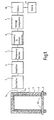
- Coating 2 and floor 4 constitute the first (target) and second (counter) electrodes of a capacitor which forms part of an electrical circuit in an oscillator indicated broadly by block 5.
- the oscillator is chosen to oscillate at a normal frequency of 100kH. When an intruder walking on floor 4 approaches painted surface 2, the dielectric between coating 2 and floor 4 increases causing a corresponding increase in the capacitance of the capacitor and thereby a reduction in the output frequency of the oscillator.
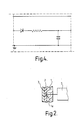
- connection between conductive undercoat 2 and wire 5a which connects the undercoat 2 into the oscillator circuit is shown more clearly in Figure 2.
- the connection is made to an aluminium contact strip 1a a adhesively bonded to frame 1 and painted over by undercoat 2.
- the output frequency imposed by oscillator 5 is fed as a signal via a conventional amplifier 6 to a frequency divider 7 where the frequency is reduced to one tenth of its original value.
- the reduced frequency signal is then fed to a convertor 8 where its frequency is converted to a voltage.
- the voltage is fed to a conventional comparator 9 where it is compared with an adjustable reference voltage so that a "eduction in the output frequency of oscillator 5 can be easily detected as a reduction in voltage. Accordingly converter 8 and comparator 9 together constitute a response means which enables a change in the frequency to be detected.
- a reduction in voltage detected by comparator 9 is used to actuate a conventional relay 10 which in turn may be used to switch on an alarm 11.
- Block 5 broadly indicates a unijunction relaxation oscillator comprising a switching means which is unijunction transistor 51 and a capacitor consisting of undercoat 2 and floor 4, the counter electrode.
- the oscillator circuit also contains inductances 52 and resistor 53.
- undercoat 2 (the target electrode) is connected via a 10 Mohm resistance 55 (not shown in Figure 1) to earth as is one pole of the 12v power supply so as to comply with the safety requirements of British Standard BS 6800 : 1986.
- Divider 7 contains a presettable "divide-by-N" counter chip 71 of the type HEF 4018B described on pages 189 to 194 of the "Mullard Technical Handbook", Book 4 part 4 published in London by Mullard Limited in July 1983.
- Convertor 8 contains a precision frequency to voltage converter 81 of the type LM331 described on pages 8-251 to 8-257 of the "Linear Databook” published in 1982 by National Semiconductor Corporation of Santa Clara, California see especially page 8-257.
- Voltage comparator 9 which contains chip 91 of the type LM741 described on pages 3-2 to 3-259 of the "Linear Databook” ibid. Again, the content of these pages is herein incorporated by reference.
- Figure 4 indicates a form of diode pump which could be used as a simple means for converting frequency to voltage instead of the combination of divider 7 and converter 8.
- This invention also provides an intruder 30 detection system which comprises a proximity detector according to the invention, an alarm and a relay of enabling the switch to actuate the alarm.
Landscapes
- Physics & Mathematics (AREA)
- General Physics & Mathematics (AREA)
- Geophysics And Detection Of Objects (AREA)
Applications Claiming Priority (2)
| Application Number | Priority Date | Filing Date | Title |
|---|---|---|---|
| GB888806734A GB8806734D0 (en) | 1988-03-22 | 1988-03-22 | Concealable proximity switch |
| GB8806734 | 1988-03-22 |
Publications (1)
| Publication Number | Publication Date |
|---|---|
| EP0334531A1 true EP0334531A1 (de) | 1989-09-27 |
Family
ID=10633832
Family Applications (1)
| Application Number | Title | Priority Date | Filing Date |
|---|---|---|---|
| EP19890302494 Withdrawn EP0334531A1 (de) | 1988-03-22 | 1989-03-14 | Versteckbarer Näherungsdetektor |
Country Status (2)
| Country | Link |
|---|---|
| EP (1) | EP0334531A1 (de) |
| GB (1) | GB8806734D0 (de) |
Cited By (6)
| Publication number | Priority date | Publication date | Assignee | Title |
|---|---|---|---|---|
| US5764145A (en) * | 1993-10-29 | 1998-06-09 | Hansson; Goran | Capacitive detector device and alarm system |
| WO1999062040A1 (fr) * | 1998-05-26 | 1999-12-02 | Valeo Securite Habitacle | Dispositif de detection de presence d'un corps humain |
| US6741163B1 (en) * | 1996-08-13 | 2004-05-25 | Corinna A. Roberts | Decorative motion detector |
| US7489142B2 (en) | 2004-08-31 | 2009-02-10 | Koninklijke Philips Electronics N.V. | Proximity sensor for X-ray apparatus |
| WO2011104407A1 (es) * | 2010-02-25 | 2011-09-01 | Micromag 2000 S.L. | Sistema sensor capacitivo para dispositivos de protección perimetral |
| WO2018021919A1 (en) * | 2016-07-27 | 2018-02-01 | Resene Paints Limited | Proximity sensing and control system |
-
1988
- 1988-03-22 GB GB888806734A patent/GB8806734D0/en active Pending
-
1989
- 1989-03-14 EP EP19890302494 patent/EP0334531A1/de not_active Withdrawn
Non-Patent Citations (1)
| Title |
|---|
| NO RELEVANT DOCUMENTS HAVE BEEN DISCLOSED * |
Cited By (7)
| Publication number | Priority date | Publication date | Assignee | Title |
|---|---|---|---|---|
| US5764145A (en) * | 1993-10-29 | 1998-06-09 | Hansson; Goran | Capacitive detector device and alarm system |
| US6741163B1 (en) * | 1996-08-13 | 2004-05-25 | Corinna A. Roberts | Decorative motion detector |
| WO1999062040A1 (fr) * | 1998-05-26 | 1999-12-02 | Valeo Securite Habitacle | Dispositif de detection de presence d'un corps humain |
| US7489142B2 (en) | 2004-08-31 | 2009-02-10 | Koninklijke Philips Electronics N.V. | Proximity sensor for X-ray apparatus |
| WO2011104407A1 (es) * | 2010-02-25 | 2011-09-01 | Micromag 2000 S.L. | Sistema sensor capacitivo para dispositivos de protección perimetral |
| ES2376453A1 (es) * | 2010-02-25 | 2012-03-14 | Micromag 2000 S.L. | Sistema sensor capacitivo para dispositivos de protección perimetral. |
| WO2018021919A1 (en) * | 2016-07-27 | 2018-02-01 | Resene Paints Limited | Proximity sensing and control system |
Also Published As
| Publication number | Publication date |
|---|---|
| GB8806734D0 (en) | 1988-04-20 |
Similar Documents
| Publication | Publication Date | Title |
|---|---|---|
| US4918568A (en) | Air quality control systems | |
| EP0334531A1 (de) | Versteckbarer Näherungsdetektor | |
| JPH06511561A (ja) | 容量性水滴センサ | |
| US5442334A (en) | Security system having deactivatable security tag | |
| EP1464206A1 (de) | Verfahren zur bereitstellung eines elektrolumineszenzbeschichtungssystems für ein fahrzeug und elektrolumineszenzbeschichtungssystem dafür | |
| US4415946A (en) | Antistatic chairmat | |
| GB1153529A (en) | Improvements relating to Flame Spraying | |
| ES8604631A1 (es) | Procedimiento de preparacion de un pigmento a base de oxido de estano dopado mediante oxido de antimonio | |
| Cardillo et al. | Heating, ventilation, and air conditioning control by range-Doppler and micro-Doppler radar sensor | |
| AU2017228221A1 (en) | Touch sensitive control system for non-electronic display substrate surfaces | |
| US4317855A (en) | Electrically conductive white coatings | |
| US7283053B2 (en) | RFID radio frequency identification or property monitoring method and associated apparatus | |
| US5098735A (en) | Shielding of houses and buildings from low and high frequency EMF radiation by organic based stabilized nickel conductive coatings | |
| EP0080618A3 (de) | Elektrostatische Koalesziereinrichtung | |
| US3442699A (en) | Electric signal recording blank | |
| FR2668491B1 (fr) | Peintures antistatiques et radiotransparentes blanches pour satellites. | |
| US5747150A (en) | Electrostatic powder coating method | |
| CA2119958A1 (en) | Micro-controller based high voltage power supply | |
| CN114876152B (zh) | 一种智能地坪结构及其施工方法 | |
| JPS6324581A (ja) | 面抵抗体 | |
| WO2018021919A9 (en) | Proximity sensing and control system | |
| EP0376863A3 (de) | Verfahren zur Bildung leitender Filme | |
| JPH01264196A (ja) | 分散型el素子 | |
| IE39206B1 (en) | Curing agents | |
| Huebner et al. | Dielectric and Electrical Properties of BaTiO sub 3 Composites.(Retroactive Coverage) |
Legal Events
| Date | Code | Title | Description |
|---|---|---|---|
| PUAI | Public reference made under article 153(3) epc to a published international application that has entered the european phase |
Free format text: ORIGINAL CODE: 0009012 |
|
| AK | Designated contracting states |
Kind code of ref document: A1 Designated state(s): AT BE CH DE ES FR GB GR IT LI LU NL SE |
|
| 17P | Request for examination filed |
Effective date: 19890809 |
|
| STAA | Information on the status of an ep patent application or granted ep patent |
Free format text: STATUS: THE APPLICATION IS DEEMED TO BE WITHDRAWN |
|
| 18D | Application deemed to be withdrawn |
Effective date: 19921001 |