EP0334449A2 - Blowmoulding machine with an adjustable dwellperiod - Google Patents
Blowmoulding machine with an adjustable dwellperiod Download PDFInfo
- Publication number
- EP0334449A2 EP0334449A2 EP89200698A EP89200698A EP0334449A2 EP 0334449 A2 EP0334449 A2 EP 0334449A2 EP 89200698 A EP89200698 A EP 89200698A EP 89200698 A EP89200698 A EP 89200698A EP 0334449 A2 EP0334449 A2 EP 0334449A2
- Authority
- EP
- European Patent Office
- Prior art keywords
- signal
- piston
- blow molding
- speed
- ejection
- Prior art date
- Legal status (The legal status is an assumption and is not a legal conclusion. Google has not performed a legal analysis and makes no representation as to the accuracy of the status listed.)
- Granted
Links
- 238000000071 blow moulding Methods 0.000 title claims abstract description 35
- 238000000034 method Methods 0.000 claims abstract description 40
- 230000008569 process Effects 0.000 claims abstract description 40
- 239000004033 plastic Substances 0.000 claims abstract description 31
- 230000010354 integration Effects 0.000 claims abstract description 11
- 230000001105 regulatory effect Effects 0.000 claims abstract description 10
- 230000008859 change Effects 0.000 claims abstract description 9
- 230000001276 controlling effect Effects 0.000 claims abstract description 3
- 238000011156 evaluation Methods 0.000 claims description 17
- 230000004069 differentiation Effects 0.000 claims description 3
- 229920001169 thermoplastic Polymers 0.000 description 9
- 239000004416 thermosoftening plastic Substances 0.000 description 7
- 239000012815 thermoplastic material Substances 0.000 description 5
- 230000006870 function Effects 0.000 description 4
- 239000000463 material Substances 0.000 description 4
- 230000009467 reduction Effects 0.000 description 3
- 230000015572 biosynthetic process Effects 0.000 description 2
- 239000010720 hydraulic oil Substances 0.000 description 2
- 238000001125 extrusion Methods 0.000 description 1
Images
Classifications
-
- B—PERFORMING OPERATIONS; TRANSPORTING
- B29—WORKING OF PLASTICS; WORKING OF SUBSTANCES IN A PLASTIC STATE IN GENERAL
- B29C—SHAPING OR JOINING OF PLASTICS; SHAPING OF MATERIAL IN A PLASTIC STATE, NOT OTHERWISE PROVIDED FOR; AFTER-TREATMENT OF THE SHAPED PRODUCTS, e.g. REPAIRING
- B29C48/00—Extrusion moulding, i.e. expressing the moulding material through a die or nozzle which imparts the desired form; Apparatus therefor
- B29C48/03—Extrusion moulding, i.e. expressing the moulding material through a die or nozzle which imparts the desired form; Apparatus therefor characterised by the shape of the extruded material at extrusion
- B29C48/09—Articles with cross-sections having partially or fully enclosed cavities, e.g. pipes or channels
-
- B—PERFORMING OPERATIONS; TRANSPORTING
- B29—WORKING OF PLASTICS; WORKING OF SUBSTANCES IN A PLASTIC STATE IN GENERAL
- B29C—SHAPING OR JOINING OF PLASTICS; SHAPING OF MATERIAL IN A PLASTIC STATE, NOT OTHERWISE PROVIDED FOR; AFTER-TREATMENT OF THE SHAPED PRODUCTS, e.g. REPAIRING
- B29C48/00—Extrusion moulding, i.e. expressing the moulding material through a die or nozzle which imparts the desired form; Apparatus therefor
- B29C48/001—Combinations of extrusion moulding with other shaping operations
- B29C48/0017—Combinations of extrusion moulding with other shaping operations combined with blow-moulding or thermoforming
-
- B—PERFORMING OPERATIONS; TRANSPORTING
- B29—WORKING OF PLASTICS; WORKING OF SUBSTANCES IN A PLASTIC STATE IN GENERAL
- B29C—SHAPING OR JOINING OF PLASTICS; SHAPING OF MATERIAL IN A PLASTIC STATE, NOT OTHERWISE PROVIDED FOR; AFTER-TREATMENT OF THE SHAPED PRODUCTS, e.g. REPAIRING
- B29C48/00—Extrusion moulding, i.e. expressing the moulding material through a die or nozzle which imparts the desired form; Apparatus therefor
- B29C48/25—Component parts, details or accessories; Auxiliary operations
- B29C48/30—Extrusion nozzles or dies
- B29C48/32—Extrusion nozzles or dies with annular openings, e.g. for forming tubular articles
-
- B—PERFORMING OPERATIONS; TRANSPORTING
- B29—WORKING OF PLASTICS; WORKING OF SUBSTANCES IN A PLASTIC STATE IN GENERAL
- B29C—SHAPING OR JOINING OF PLASTICS; SHAPING OF MATERIAL IN A PLASTIC STATE, NOT OTHERWISE PROVIDED FOR; AFTER-TREATMENT OF THE SHAPED PRODUCTS, e.g. REPAIRING
- B29C48/00—Extrusion moulding, i.e. expressing the moulding material through a die or nozzle which imparts the desired form; Apparatus therefor
- B29C48/25—Component parts, details or accessories; Auxiliary operations
- B29C48/36—Means for plasticising or homogenising the moulding material or forcing it through the nozzle or die
- B29C48/475—Means for plasticising or homogenising the moulding material or forcing it through the nozzle or die using pistons, accumulators or press rams
-
- B—PERFORMING OPERATIONS; TRANSPORTING
- B29—WORKING OF PLASTICS; WORKING OF SUBSTANCES IN A PLASTIC STATE IN GENERAL
- B29C—SHAPING OR JOINING OF PLASTICS; SHAPING OF MATERIAL IN A PLASTIC STATE, NOT OTHERWISE PROVIDED FOR; AFTER-TREATMENT OF THE SHAPED PRODUCTS, e.g. REPAIRING
- B29C48/00—Extrusion moulding, i.e. expressing the moulding material through a die or nozzle which imparts the desired form; Apparatus therefor
- B29C48/25—Component parts, details or accessories; Auxiliary operations
- B29C48/92—Measuring, controlling or regulating
-
- B—PERFORMING OPERATIONS; TRANSPORTING
- B29—WORKING OF PLASTICS; WORKING OF SUBSTANCES IN A PLASTIC STATE IN GENERAL
- B29C—SHAPING OR JOINING OF PLASTICS; SHAPING OF MATERIAL IN A PLASTIC STATE, NOT OTHERWISE PROVIDED FOR; AFTER-TREATMENT OF THE SHAPED PRODUCTS, e.g. REPAIRING
- B29C49/00—Blow-moulding, i.e. blowing a preform or parison to a desired shape within a mould; Apparatus therefor
- B29C49/42—Component parts, details or accessories; Auxiliary operations
- B29C49/78—Measuring, controlling or regulating
- B29C2049/788—Controller type or interface
- B29C2049/78805—Computer or PLC control
-
- B—PERFORMING OPERATIONS; TRANSPORTING
- B29—WORKING OF PLASTICS; WORKING OF SUBSTANCES IN A PLASTIC STATE IN GENERAL
- B29C—SHAPING OR JOINING OF PLASTICS; SHAPING OF MATERIAL IN A PLASTIC STATE, NOT OTHERWISE PROVIDED FOR; AFTER-TREATMENT OF THE SHAPED PRODUCTS, e.g. REPAIRING
- B29C2948/00—Indexing scheme relating to extrusion moulding
- B29C2948/92—Measuring, controlling or regulating
- B29C2948/92504—Controlled parameter
- B29C2948/92571—Position, e.g. linear or angular
-
- B—PERFORMING OPERATIONS; TRANSPORTING
- B29—WORKING OF PLASTICS; WORKING OF SUBSTANCES IN A PLASTIC STATE IN GENERAL
- B29C—SHAPING OR JOINING OF PLASTICS; SHAPING OF MATERIAL IN A PLASTIC STATE, NOT OTHERWISE PROVIDED FOR; AFTER-TREATMENT OF THE SHAPED PRODUCTS, e.g. REPAIRING
- B29C2948/00—Indexing scheme relating to extrusion moulding
- B29C2948/92—Measuring, controlling or regulating
- B29C2948/92504—Controlled parameter
- B29C2948/9258—Velocity
- B29C2948/9259—Angular velocity
-
- B—PERFORMING OPERATIONS; TRANSPORTING
- B29—WORKING OF PLASTICS; WORKING OF SUBSTANCES IN A PLASTIC STATE IN GENERAL
- B29C—SHAPING OR JOINING OF PLASTICS; SHAPING OF MATERIAL IN A PLASTIC STATE, NOT OTHERWISE PROVIDED FOR; AFTER-TREATMENT OF THE SHAPED PRODUCTS, e.g. REPAIRING
- B29C2948/00—Indexing scheme relating to extrusion moulding
- B29C2948/92—Measuring, controlling or regulating
- B29C2948/92504—Controlled parameter
- B29C2948/92609—Dimensions
- B29C2948/92657—Volume or quantity
-
- B—PERFORMING OPERATIONS; TRANSPORTING
- B29—WORKING OF PLASTICS; WORKING OF SUBSTANCES IN A PLASTIC STATE IN GENERAL
- B29C—SHAPING OR JOINING OF PLASTICS; SHAPING OF MATERIAL IN A PLASTIC STATE, NOT OTHERWISE PROVIDED FOR; AFTER-TREATMENT OF THE SHAPED PRODUCTS, e.g. REPAIRING
- B29C2948/00—Indexing scheme relating to extrusion moulding
- B29C2948/92—Measuring, controlling or regulating
- B29C2948/92819—Location or phase of control
- B29C2948/92857—Extrusion unit
- B29C2948/92876—Feeding, melting, plasticising or pumping zones, e.g. the melt itself
- B29C2948/92885—Screw or gear
-
- B—PERFORMING OPERATIONS; TRANSPORTING
- B29—WORKING OF PLASTICS; WORKING OF SUBSTANCES IN A PLASTIC STATE IN GENERAL
- B29C—SHAPING OR JOINING OF PLASTICS; SHAPING OF MATERIAL IN A PLASTIC STATE, NOT OTHERWISE PROVIDED FOR; AFTER-TREATMENT OF THE SHAPED PRODUCTS, e.g. REPAIRING
- B29C49/00—Blow-moulding, i.e. blowing a preform or parison to a desired shape within a mould; Apparatus therefor
- B29C49/02—Combined blow-moulding and manufacture of the preform or the parison
- B29C49/04—Extrusion blow-moulding
- B29C49/041—Extrusion blow-moulding using an accumulator head
Definitions
- the invention relates to a blow molding machine for blow molding hollow bodies with a storage head, which is connected to a plastic extruder and from which, in the filled state, an ejection piston presses the plastic through an annularly shaped outlet opening to produce a preform, with a blow mold to form a hollow body from the preform and with a control circuit which, after completion of a blow molding process, derives a piston control signal for regulating the position of the ejection piston from a comparison signal which is formed from the difference between the actual position and the desired position of the ejection piston, the desired position being determined by integration from a predetermined speed setpoint profile.
- tubular preforms are produced from the relevant plastic material by means of a storage head and are inflated to a final size between two hollow mold halves (blow mold) in a further operation.
- the storage head is connected to an extruder from which the thermoplastic material reaches the storage head.
- the storage head has an annular gap-shaped outlet opening that is adjustable.
- the thermoplastic is pressed out of the outlet opening by an ejection piston.
- the resulting preform is stretched unevenly depending on the shape of the hollow body to be obtained.
- a Uniform wall thickness of the hollow body therefore requires profiling the wall thickness of the preform (wall thickness setpoint profile). This wall thickness setpoint profile of the preform is realized by adjusting the gap width of the outlet opening during the extrusion process and changing the speed of the ejection piston.
- a blow molding machine operating in this way is known from DE-OS 34 16 781.
- the speed of the ejection piston is determined by regulating the position of the ejection piston.
- a piston actuator moves the ejection piston depending on the piston control signal from a position controller.
- the position controller receives a comparison signal which is formed in a superposition stage by subtracting the actual position from the target position.
- the setpoint position is determined by integration from a specified speed setpoint profile.
- the speed setpoint profile is divided into a certain number of segments that identify different positions. The speed can change from one segment to another. This speed profile specified by the profile corresponds to the profile for the wall thickness control at the outlet opening.
- the speed setpoint profile is determined for a certain volume within the storage head. If the volume of the plastic within the storage head remains constant during successive ejection processes, a preform (reference preform) is obtained which has essentially the same features, namely constant length and constant volume. It is necessary that the inflow of plastic from the extruder remains constant. This changes Plastic inflow, for example due to a change in the speed of the extruder, also changes the ejected hose.
- the ejection process usually begins when the storage head is filled with thermoplastic material (until the desired filling level is reached) and the blow molding process for producing a hollow body has been completed. If the blow molding process has not yet ended, plastic is still filled into the storage head until the ejection process can begin after the blow molding process has ended.
- the additional plastic inflow caused by the overfilling of the storage head causes changes in the preform.
- the preform is only profiled when the additional plastic has been ejected as a so-called “pre-hose”.
- the invention is therefore based on the object of providing a blow molding machine for blow molding hollow bodies, in which a loss of material is reduced and the number of hollow bodies to be produced per unit of time is increased, the preform arising during the ejection process largely corresponding to a reference preform.
- control circuit - The comparison signal is superimposed with an inflow signal which corresponds to the change in volume due to the plastic flowing out of the extruder when the filling of the storage head is ejected, and - The deviation between an actual cushion and a target cushion for the remaining plastic in the storage head at the end of the ejection process is reduced by controlling the speed of the extruder.
- a preform is produced which largely corresponds to the reference preform even when the extruder inflow changes.
- the speed setpoint profile has been determined for a constant volume in the storage head. It has been assumed that a constant inflow of thermoplastic material from the extruder occurs. For this speed setpoint profile, a constant set fill level at which the ejection process begins and a set cushion at which the ejection process ends.
- the change in the inflow of plastic from the extruder is compensated for by an inflow signal which is superimposed on the comparison signal.
- the inflow signal is predetermined for the reference preform. It corresponds to the amount of thermoplastic that flows into the storage head during the formation of a reference preform.
- This inflow signal influences the desired position of the ejection piston so that the plastic which has additionally or less flowed in from the extruder cannot change the volume of the preform during the ejection process. Only the plastic that corresponds to the volume of the reference preform is ejected.
- the control circuit also compares the plastic (actual cushion) remaining after an ejection process the target cushion. Depending on the comparison, an actuating signal for regulating the speed of the extruder is derived in order to bring the actual cushion closer to the target cushion.
- the ejection process begins as soon as the blow molding process has ended. If the target filling level has not yet been reached at the start of the ejection process, the actual cushion after the ejection process is smaller than the target cushion. In this case, the speed must be increased. A reduction in the speed is necessary if the target filling level has been exceeded at the start of the ejection process. This measure ensures that the preform largely corresponds to the reference preform and the actual cushion is brought closer to the target cushion.
- the control circuit the actual cushion is subtracted from the end position setpoint by subtracting the inflow signal value measured at the end of an ejection process, - Forms a difference signal between a target cushion and the actual cushion and - A speed control signal for an extruder actuator to set the speed generated from the difference signal by differentiation and integration.
- the one determined at the end of an ejection process by integration from the speed setpoint profile End position setpoint does not correspond to the actual cushion.
- this is additionally superimposed with an inflow signal.
- This inflow signal must therefore be taken into account when determining the actual cushion from the end position setpoint.
- the speed control signal for the extruder actuator is formed by differentiation and integration. It is also possible to determine the actual cushion by measuring the position value of the ejection piston at the end of the ejection process.
- the inflow signal is formed in the control circuit from the speed control signal by integration. Since the volume is proportional to the plastic flow integrated per unit of time, but the flow is proportional to the speed and the speed is in turn proportional to the speed control signal, the inflow signal results from integration from the speed control signal. With each new ejection process, the integrator must be set to zero, since the amount of plastic supplied at the start of the ejection process is zero.
- the discharge piston is regulated between the start of the discharge process and the end position setpoint. It is provided here that a piston actuator sets the ejection piston as a function of the piston control signal for regulating the ejection piston. After the end position setpoint has been reached, the piston actuator uses a reset signal from the control circuit to reverse the ejection piston to its starting position by filling the storage head from the extruder.
- the control circuit can be implemented as a digital computing arrangement (microcomputer) or by means of discrete components.
- the control circuit contains a differential integral controller which generates the speed control signal for the extruder control element from the difference signal formed with a comparison stage.
- the control circuit contains a first integrator for forming the inflow signal from the speed control signal for the extruder actuator.
- the control circuit also contains an evaluation circuit, which - Causes the start of the ejection piston after completion of a blow molding process and - Determines the end position setpoint and the actual cushion.
- Another circuit controlled by the evaluation circuit supplies the speed setpoint profile.
- a downstream second integrator integrates the speed setpoints which are fed to an overlay stage in which the difference between the actual and setpoint position and the overlay of comparison and inflow signal is formed.
- the piston control signal supplied by the control circuit is generated by a position controller, which receives the signal formed by the superposition stage.
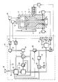
- the blow molding machine shown schematically in the single figure contains a storage head 1, which discontinuously produces 13 preforms from thermoplastic material.
- One not shown here Blow molding is used to press the preforms into hollow bodies.
- the thermoplastic plastic 13 is supplied by an extruder 2, which is controlled by an extruder actuator 3.
- the extruder actuator 3 adjusts the speed of the extruder and thus determines the flow of the thermoplastic 13 flowing into the storage head 1.
- the thermoplastic 13 which has entered the cylindrical storage head 1 from the extruder 2 is pressed out by an ejection piston 4 through an annular opening 5.
- the gap width is continuously adjusted by a mandrel 6.
- the wall thickness of a preform can still be partially adjusted by means of a flexible nozzle ring 7 by means of several actuators (partial wall thickness adjustment). In the drawing, the nozzle ring 7 is adjusted by two wall thickness actuators 9 and 10 as an example.
- the mandrel 6 is adjusted by a mandrel actuator 14.
- thermoplastic 13 is pressed out of the annular gap-shaped outlet opening 5 by means of the ejection piston 4 by hydraulic oil filling into the cavity 12 of the storage head 1, which is not filled with thermoplastic 13.
- the hydraulic oil flows out of the cavity 12 again, and the ejection piston 4 is raised into its starting position by the thermoplastic material 13 supplied by the extruder 2.
- the memory head 1 is regulated or controlled by a control circuit 15 which is constructed from discrete digital components.
- the control circuit 15 contains an evaluation circuit 16 which supplies the actual position of the ejection piston 4 determined by the position transmitter 11 via an analog-digital converter 17.
- the desired filling level and the desired cushion are input to the evaluation circuit 16 via an input unit 18.
- the desired cushion represents the remaining plastic 13 remaining in the storage head 1 at the end of an ejection process.
- the evaluation circuit 16 also contains a status signal via a line 35 from a blow mold control circuit, which indicates whether the blow mold is ready to accept a new preform (the blow molding process is completed ).
- the evaluation circuit contains an inflow signal value at the end of an ejection process.
- a circuit 20 is given a start signal, whereupon the latter outputs a speed setpoint profile.
- the circuit 20 has been supplied with the start and end position setpoint by the evaluation circuit 16 before the ejection process begins.
- the speed setpoint profile has been determined for a reference preform and represents the speed of the ejection piston as a function of the position of the ejection piston 4 between the set filling level and the set cushion.
- the speed setpoint profile is divided into individual segments which identify different positions. The speed can change linearly from segment to segment.
- the blow molding process can be completed sooner or later than the filling of the storage head 1 up to the desired filling level.
- the evaluation circuit 16 determines the end position setpoint by the following calculation: First, the setpoint stroke is obtained by subtracting the setpoint cushion from the target level. The end position setpoint is then determined by a further subtraction of the setpoint stroke from the start position setpoint.
- the speed setpoints output by the circuit 20 are integrated in an integrator 21 and fed to a superposition stage 22 as the setpoint position.
- the setpoint position supplied by integrator 21 is fed back to circuit 20 and serves to switch the speed setpoint profile as a function of the setpoint position. If the circuit 20 determines that the end position setpoint has been reached, the output of the speed setpoint profile is ended.
- the integrator 21 is set to the actual position by the evaluation circuit 16 via the line 36 before the start of an ejection process.
- the superposition stage 22 is also supplied with the actual position by the analog-to-digital converter 17 and by an additional integrator 23.
- the inflow signal is formed by integrating the speed control signal in the integrator 23 for the extruder actuator 3.
- the inflow signal and the actual position are subtracted from the target position.
- the signal resulting from the subtraction is supplied to a position controller 24, which generates a piston control signal which is transmitted to the piston actuator 19 via a reset circuit 25 and a digital-to-analog converter 26.
- a signal is fed from the evaluation circuit 16 via a line 38 to the reset circuit 25, which causes the piston actuator 19 to be supplied with the piston actuator signal at the start of the ejection process.
- the piston actuator 19 is switched so that the ejection piston 4 by filling the storage head 1 with thermoplastic in returns to its starting position. Even if the ejection piston 4 has completely pressed the plastic 13 out of the storage head 1, ie the ejection piston 4 has reached the mechanical stop of the storage head 1, the evaluation circuit 16 causes the ejection piston 4 to be reversed into its starting position by a signal via the line 38 to the Reset circuit 25.
- the reference preform has been determined for a certain volume within the storage head 1 and a certain inflow of plastic from the extruder 2 during the ejection process. Since the plastic supplied by the extruder 2 can change during the ejection process, the desired position must then be compensated for in order to produce a preform that corresponds to the reference preform.
- the volume of the plastic that additionally or less flows into the storage head 1 during the ejection process is proportional to the inflow of plastic integrated per unit of time. This flow is in turn proportional to the speed and the speed proportional to the speed control signal.
- the inflow signal results which corresponds to the inflowing volume during the ejection process.
- the integrator 23 is set to zero by the evaluation circuit 16 via the line 37 by a reset signal before the start of an ejection process.
- the evaluation circuit 16 calculates by subtracting the inflow signal value measured at the end of the ejection process from the final position setpoint, the actual cushion.
- the end position setpoint is the setpoint position of the speed setpoint profile at the end of the profile output. In other words, the value which the overlay stage 22 is supplied by the integrator 23 at the end of the profile output.
- the actual cushion is fed to an input of a comparison stage 28, the other input of which is supplied to the target cushion from a memory element 29.
- the difference signal between the target cushion and the actual cushion is formed by subtracting the actual cushion from the target cushion.
- the difference signal is fed to a differential integral controller 34, which generates the speed control signal, which is fed to the integer 23 and, via a digital-analog converter 27, to the extruder actuator 3.
- this controller 34 it is achieved that the actual cushion is brought closer to the target cushion. Studies have shown that the control loop is stable.
- the wall thickness actuators 9 and 10 and the mandrel actuator 14 are controlled by a circuit 30 which supplies the respective setpoints (wall thickness setpoint profiles) via digital-to-analog converters 31, 32 and 33 for the mandrel position and the wall thicknesses as a function of the setpoint position.
Abstract
Die Erfindung bezieht sich auf eine Blasformmaschine zum Blasformen von Hohlkörpern mit einem Speicherkopf (1) zur Erzeugung eines Vorformlings und mit einer Blasform zur Bildung eines Hohlkörpers aus dem Vorformling. Eine Steuerschaltung (15) leitet nach Abschluß eines Blasformvorganges ein Kolbenstellsignal zur Regelung der Position eines Ausstoßkolbens (4) im Speicherkopf (1) aus einem aus der Istposition und Sollposition des Ausstoßkolbens (4) gebildeten Vergleichssignal ab. Die Sollposition wird durch Integration aus einem vorgegebenen Geschwindigkeitssollwertprofil ermittelt. Ferner überlagert die Steuerschaltung (15) das Vergleichssignal mit einem Zuflußsignal, welches der Volumenänderung durch den beim Ausstoßen der Füllung des Speicherkopfes (1) aus einem Extruder (2) nachfließenden Kunststoff entspricht. Die Abweichung zwischen einem Istpolster und einem Sollpolster für den verbleibenden Kunststoff im Speicherkopf am Ende des Ausstoßvorganges wird durch Regelung der Drehzahl des Extruders verringert.The invention relates to a blow molding machine for blow molding hollow bodies with a storage head (1) for producing a preform and with a blow mold for forming a hollow body from the preform. After completion of a blow molding process, a control circuit (15) derives a piston control signal for regulating the position of an ejection piston (4) in the storage head (1) from a comparison signal formed from the actual position and the desired position of the ejection piston (4). The setpoint position is determined by integration from a predefined speed setpoint profile. Furthermore, the control circuit (15) superimposes the comparison signal with an inflow signal which corresponds to the change in volume due to the plastic flowing in when the filling of the storage head (1) is ejected from an extruder (2). The deviation between an actual cushion and a target cushion for the remaining plastic in the storage head at the end of the ejection process is reduced by controlling the speed of the extruder.
Description
Die Erfindung bezieht sich auf eine Blasformmaschine zum Blasformen von Hohlkörpern
mit einem Speicherkopf, der mit einem Kunststoff liefernden Extruder verbunden ist und aus dem im gefüllten Zustand ein Ausstoßkolben den Kunststoff durch eine ringspaltförmige Austrittsöffnung zur Erzeugung eines Vorformlings preßt,
mit einer Blasform zur Bildung eines Hohlkörpers aus dem Vorformling und
mit einer Steuerschaltung, die nach Abschluß eines Blasformvorgangs ein Kolbenstellsignal zur Regelung der Position des Ausstoßkolbens aus einem Vergleichssignal ableitet, welches aus der Differenz zwischen Istposition und Sollposition des Ausstoßkolbens gebildet ist, wobei die Sollposition durch Integration aus einem vorgegebenen Geschwindigkeitssollwertprofil ermittelt wird.The invention relates to a blow molding machine for blow molding hollow bodies
with a storage head, which is connected to a plastic extruder and from which, in the filled state, an ejection piston presses the plastic through an annularly shaped outlet opening to produce a preform,
with a blow mold to form a hollow body from the preform and
with a control circuit which, after completion of a blow molding process, derives a piston control signal for regulating the position of the ejection piston from a comparison signal which is formed from the difference between the actual position and the desired position of the ejection piston, the desired position being determined by integration from a predetermined speed setpoint profile.
Für das Blasformen von Hohlkörpern aus thermoplastischem Kunststoff werden mittels eines Speicherkopfes schlauchförmige Vorformlinge aus dem betreffenden Kunststoffmaterial hergestellt und in einem weiteren Arbeitsgang zwischen zwei Hohlformenhälften (Blasform) zur Endgröße aufgeblasen. Der Speicherkopf ist mit einem Extruder verbunden, aus dem der thermoplastische Kunststoff in den Speicherkopf gelangt. Der Speicherkopf hat eine ringspaltförmige Austrittsöffnung, die verstellbar ist. Der thermoplastische Kunststoff wird durch einen Ausstoßkolben aus der Austrittsöffnung herausgepreßt. Der dabei entstehende Vorformling wird in Abhängigkeit von der Form des zu gewinnenden Hohlkörpers ungleichmäßig gedehnt. Eine gleichmäßige Wandstärke des Hohlkörpers setzt daher eine Profilierung der Wandstärke beim Vorformling voraus (Wandstärkesollwertprofil). Dieses Wandstärkesollwertprofil des Vorformlings wird durch Verstellung der Spaltbreite der Austrittsöffnung während des Auspreßvorgangs und einer Änderung der Geschwindigkeit des Ausstoßkolbens realisiert. Eine auf diese Weise arbeitende Blasformmaschine ist aus der DE-OS 34 16 781 bekannt.For the blow molding of hollow bodies made of thermoplastic plastic, tubular preforms are produced from the relevant plastic material by means of a storage head and are inflated to a final size between two hollow mold halves (blow mold) in a further operation. The storage head is connected to an extruder from which the thermoplastic material reaches the storage head. The storage head has an annular gap-shaped outlet opening that is adjustable. The thermoplastic is pressed out of the outlet opening by an ejection piston. The resulting preform is stretched unevenly depending on the shape of the hollow body to be obtained. A Uniform wall thickness of the hollow body therefore requires profiling the wall thickness of the preform (wall thickness setpoint profile). This wall thickness setpoint profile of the preform is realized by adjusting the gap width of the outlet opening during the extrusion process and changing the speed of the ejection piston. A blow molding machine operating in this way is known from DE-OS 34 16 781.
Während eines Ausstoßvorganges wird die Geschwindigkeit des Ausstoßkolbens durch Regelung der Position des Ausstoßkolbens bestimmt. Ein Kolbenstellglied verschiebt den Ausstoßkolben in Abhängigkeit vom Kolbenstellsignal eines Positionsreglers. Der Positionsregler erhält ein Vergleichssignal, das in einer Überlagerungsstufe durch Subtraktion der Istposition von der Sollposition gebildet ist. Die Sollposition wird dabei durch Integration aus einem vorgegebenen Geschwindigkeitssollwertprofil ermittelt. Das Geschwindigkeitssollwertprofil ist in eine bestimmte Anzahl von Segmenten eingeteilt, die verschiedene Positionen kennzeichnen. Von einem Segment zum anderen kann eine Änderung der Geschwindigkeit stattfinden. Dieser durch das Profil vorgegebene Geschwindigkeitsverlauf entspricht dem Profil für die Wanddickensteuerung an der Austrittsöffnung.During an ejection process, the speed of the ejection piston is determined by regulating the position of the ejection piston. A piston actuator moves the ejection piston depending on the piston control signal from a position controller. The position controller receives a comparison signal which is formed in a superposition stage by subtracting the actual position from the target position. The setpoint position is determined by integration from a specified speed setpoint profile. The speed setpoint profile is divided into a certain number of segments that identify different positions. The speed can change from one segment to another. This speed profile specified by the profile corresponds to the profile for the wall thickness control at the outlet opening.
Das Geschwindigkeitssollwertprofil wird für ein bestimmtes Volumen innerhalb des Speicherkopfes ermittelt. Bleibt das Volumen des Kunststoffes innerhalb des Speicherkopfes bei aufeinanderfolgenden Ausstoßvorgängen konstant, ergibt sich ein Vorformling (Referenzvorformling), der im wesentlichen die gleichen Merkmale, nämlich konstante Länge und konstantes Volumen, aufweist. Hierbei ist es erforderlich, daß der Zufluß von Kunststoff aus dem Extruder konstant bleibt. Ändert sich dieser Kunststoffzufluß, z.B. durch eine Änderung der Drehzahl des Extruders, ändert sich auch der ausgestoßene Schlauch.The speed setpoint profile is determined for a certain volume within the storage head. If the volume of the plastic within the storage head remains constant during successive ejection processes, a preform (reference preform) is obtained which has essentially the same features, namely constant length and constant volume. It is necessary that the inflow of plastic from the extruder remains constant. This changes Plastic inflow, for example due to a change in the speed of the extruder, also changes the ejected hose.
Üblicherweise beginnt der Ausstoßvorgang, wenn der Speicherkopf mit thermoplastischem Kunststoff gefüllt (bis Sollfüllhöhe erreicht ist) und der Blasformvorgang zur Erzeugung eines Hohlkörpers abgeschlossen ist. Ist der Blasformvorgang noch nicht beendet, wird weiterhin Kunststoff in den Speicherkopf gefüllt, bis der Ausstoßvorgang nach Beendigung des Blasformvorganges beginnen kann. Der durch die Überfüllung des Speicherkopfes bedingte zusätzliche Kunststoffzufluß verursacht Veränderungen des Vorformlings. Die Profilierung des Vorformlings wird erst vorgenommen, wenn der zusätzliche Kunststoff als sogenannter "Vorschlauch" ausgestoßen ist. Es entsteht auch eine Wartezeit, wenn der Blasformvorgang abgeschlossen ist, aber der Speicherkopf noch nicht vollständig bis zur Sollfüllhöhe gefüllt ist. Bedingt durch die Wartezeit zwischen Abschluß des Blasformvorganges und Erreichen der Sollfüllhöhe im Speicherkopf und umgekehrt, ergibt sich ein Verlust von Material und eine Verminderung in der Anzahl der herzustellenden Hohlkörper pro Zeiteinheit (Kapazitätsverminderung).The ejection process usually begins when the storage head is filled with thermoplastic material (until the desired filling level is reached) and the blow molding process for producing a hollow body has been completed. If the blow molding process has not yet ended, plastic is still filled into the storage head until the ejection process can begin after the blow molding process has ended. The additional plastic inflow caused by the overfilling of the storage head causes changes in the preform. The preform is only profiled when the additional plastic has been ejected as a so-called “pre-hose”. There is also a waiting time when the blow molding process has been completed but the storage head has not yet been completely filled to the desired filling level. Due to the waiting time between the completion of the blow molding process and reaching the desired filling level in the storage head and vice versa, there is a loss of material and a reduction in the number of hollow bodies to be produced per unit of time (reduction in capacity).
Der Erfindung liegt daher die Aufgabe zugrunde, eine Blasformmaschine zum Blasformen von Hohlkörpern zu schaffen, bei welcher ein Verlust von Material vermindert und die Anzahl der herzustellenden Hohlkörper pro Zeiteinheit vergrößert wird, wobei der beim Ausstoßvorgang entstehende Vorformling weitgehend einem Referenzvorformling entspricht.The invention is therefore based on the object of providing a blow molding machine for blow molding hollow bodies, in which a loss of material is reduced and the number of hollow bodies to be produced per unit of time is increased, the preform arising during the ejection process largely corresponding to a reference preform.
Diese Aufgabe wird bei einer Blasformmaschine der eingangs genannten Art dadurch gelöst, daß die Steuerschaltung
- das Vergleichssignal mit einem Zuflußsignal überlagert, welches der Volumenänderung durch den beim Ausstoßen der Füllung des Speicherkopfes aus dem Extruder nachfließenden Kunststoff entspricht, und
- die Abweichung zwischen einem Istpolster und einem Sollpolster für den verbleibenden Kunststoff im Speicherkopf am Ende des Ausstoßvorganges durch Regelung der Drehzahl des Extruders verringert.This object is achieved in a blow molding machine of the type mentioned in that the control circuit
- The comparison signal is superimposed with an inflow signal which corresponds to the change in volume due to the plastic flowing out of the extruder when the filling of the storage head is ejected, and
- The deviation between an actual cushion and a target cushion for the remaining plastic in the storage head at the end of the ejection process is reduced by controlling the speed of the extruder.
Bei dieser Blasformmaschine wird ein Vorformling erzeugt, der auch bei einer Änderung des Extruderzuflußes weitgehend dem Referenzvorformling entspricht. Das Geschwindigkeitssollwertprofil ist für ein konstantes Volumen im Speicherkopf ermittelt worden. Hierbei ist vorausgesetzt worden, daß ein konstanter Zufluß von thermoplastischem Kunststoff aus dem Extruder auftritt. Für dieses Geschwindigkeitssollwertprofil ist eine konstante Sollfüllhöhe, bei welcher der Ausstoßvorgang beginnt, und ein Sollpolster ermittelt worden, bei der der Ausstoßvorgang endet. Die Änderung des Zuflußes von Kunststoff aus dem Extruder wird durch ein Zuflußsignal kompensiert, das dem Vergleichssignal überlagert wird. Das Zuflußsignal ist für den Referenzvorformling vorgegeben. Es entspricht der Menge des thermoplastischen Kunststoffes, die während der Bildung eines Referenzvorformlings in den Speicherkopf fließt. Dieses Zuflußsignal beeinflußt die Sollposition des Ausstoßkolbens so, daß der vom Extruder zusätzlich oder weniger eingeflossene Kunststoff während des Ausstoßvorganges nicht das Volumen des Vorformlings ändern kann. Es wird nur der Kunststoff ausgestoßen, der dem Volumen des Referenzvorformlings entspricht.In this blow molding machine, a preform is produced which largely corresponds to the reference preform even when the extruder inflow changes. The speed setpoint profile has been determined for a constant volume in the storage head. It has been assumed that a constant inflow of thermoplastic material from the extruder occurs. For this speed setpoint profile, a constant set fill level at which the ejection process begins and a set cushion at which the ejection process ends. The change in the inflow of plastic from the extruder is compensated for by an inflow signal which is superimposed on the comparison signal. The inflow signal is predetermined for the reference preform. It corresponds to the amount of thermoplastic that flows into the storage head during the formation of a reference preform. This inflow signal influences the desired position of the ejection piston so that the plastic which has additionally or less flowed in from the extruder cannot change the volume of the preform during the ejection process. Only the plastic that corresponds to the volume of the reference preform is ejected.
Die Steuerschaltung vergleicht noch den nach einem Ausstoßvorgang verbleibenden Kunststoff (Istpolster) mit dem Sollpolster. Abhängig vom Vergleich wird ein Stellsignal zur Regelung der Drehzahl des Extruders abgeleitet, um eine Annäherung des Istpolsters an das Sollpolster zu erreichen. Der Ausstoßvorgang beginnt, sobald der Blasformvorgang beendet ist. Ist die Sollfüllhöhe bei Beginn des Ausstoßvorganges noch nicht erreicht, ist das Istpolster nach dem Ausstoßvorgang kleiner als das Sollpolster. Eine Erhöhung der Drehzahl ist in diesem Fall erforderlich. Eine Verminderung der Drehzahl ist notwendig, wenn die Sollfüllhöhe bei Beginn des Ausstoßvorganges überschritten worden ist. Durch diese Maßnahme wird erreicht, daß der Vorformling weitgehend dem Referenzvorformling entspricht und das Istpolster dem Sollpolster angenähert wird. Es wird so geregelt, daß der restliche Kunststoff im Speicherkopf (Polster) weitgehend konstant bleibt und die Verweilzeit des Kunststoffes ebenfalls. Dies ermöglicht reproduzierbare Vorformlinge herzustellen. Es wird auch kein "Vorschlauch" ausgestoßen. Dadurch wird der Verlust von Material vermindert und die Anzahl der herzustellenden Hohlkörper pro Zeiteinheit vergrößert.The control circuit also compares the plastic (actual cushion) remaining after an ejection process the target cushion. Depending on the comparison, an actuating signal for regulating the speed of the extruder is derived in order to bring the actual cushion closer to the target cushion. The ejection process begins as soon as the blow molding process has ended. If the target filling level has not yet been reached at the start of the ejection process, the actual cushion after the ejection process is smaller than the target cushion. In this case, the speed must be increased. A reduction in the speed is necessary if the target filling level has been exceeded at the start of the ejection process. This measure ensures that the preform largely corresponds to the reference preform and the actual cushion is brought closer to the target cushion. It is regulated so that the remaining plastic in the storage head (cushion) remains largely constant and the residence time of the plastic also. This enables reproducible preforms to be produced. No "pre-hose" is ejected either. This reduces the loss of material and increases the number of hollow bodies to be produced per unit of time.
In einer ersten Ausführungsform der Erfindung ist vorgesehen, daß die Steuerschaltung
- das Istpolster durch Subtraktion des am Ende eines Ausstoßvorganges gemessenen Zuflußsignalwert von dem Endpositionssollwert subtrahiert,
- ein Differenzsignal zwischen einem Sollpolster und dem Istpolster bildet und
- aus dem Differenzsignal durch Differenzierung und Integration ein Drehzahlstellsignal für ein Extruderstellglied zur Stellung der Drehzahl erzeugt.In a first embodiment of the invention it is provided that the control circuit
the actual cushion is subtracted from the end position setpoint by subtracting the inflow signal value measured at the end of an ejection process,
- Forms a difference signal between a target cushion and the actual cushion and
- A speed control signal for an extruder actuator to set the speed generated from the difference signal by differentiation and integration.
Der am Ende eines Ausstoßvorganges durch Integration aus dem Geschwindigkeitssollwertprofil ermittelte Endpositionssollwert entspricht nicht dem Istpolster. Nach Erzeugung des Vergleichssignals durch Bildung der Differenz zwischen Ist- und Sollposition wird dieses zusätzlich mit einem Zuflußsignal überlagert. Dieses Zuflußsignal muß daher bei der Ermittlung des Istpolsters aus dem Endpositionssollwert berücksichtigt werden. Nach Ermittlung des Istpolsters und der Bildung des Differenzsignals wird durch Differenzierung und Integration das Drehzahlstellsignal für das Extruderstellglied gebildet. Es ist auch möglich, das Istpolster durch Messung des Positionswertes des Ausstoßkolbens am Ende des Ausstoßvorganges zu ermitteln.The one determined at the end of an ejection process by integration from the speed setpoint profile End position setpoint does not correspond to the actual cushion. After generating the comparison signal by forming the difference between the actual and target position, this is additionally superimposed with an inflow signal. This inflow signal must therefore be taken into account when determining the actual cushion from the end position setpoint. After determining the actual cushion and the formation of the difference signal, the speed control signal for the extruder actuator is formed by differentiation and integration. It is also possible to determine the actual cushion by measuring the position value of the ejection piston at the end of the ejection process.
Das Zuflußsignal wird in der Steuerschaltung aus dem Drehzahlstellsignal durch Integration gebildet. Da das Volumen proportional dem pro Zeiteinheit integrierten Fluß des Kunststoffes ist, der Fluß aber proportional der Drehzahl und die Drehzahl wiederum proportional dem Drehzahlstellsignal ist, ergibt sich durch Integration aus dem Drehzahlstellsignal das Zuflußsignal. Bei jedem neuen Ausstoßvorgang muß der Integrator auf Null gesetzt werden, da die zugeführte Menge des Kunststoffes bei Beginn des Ausstoßvorganges gleich Null ist.The inflow signal is formed in the control circuit from the speed control signal by integration. Since the volume is proportional to the plastic flow integrated per unit of time, but the flow is proportional to the speed and the speed is in turn proportional to the speed control signal, the inflow signal results from integration from the speed control signal. With each new ejection process, the integrator must be set to zero, since the amount of plastic supplied at the start of the ejection process is zero.
Eine Regelung des Ausstoßkolbens wird zwischen dem Start des Ausstoßvorganges und Erreichen des Endpositionssollwertes vorgenommen. Hierbei ist vorgesehen, daß ein Kolbenstellglied den Ausstoßkolben in Abhängigkeit vom Kolbenstellsignal zur Regelung des Ausstoßkolbens stellt. Nach Erreichen des Endpositionssollwertes bewirkt das Kolbenstellglied durch ein Rückstellsignal von der Steuerschaltung ein Umkehren des Ausstoßkolben in seine Startposition durch Füllung des Speicherkopfes aus dem Extruder.The discharge piston is regulated between the start of the discharge process and the end position setpoint. It is provided here that a piston actuator sets the ejection piston as a function of the piston control signal for regulating the ejection piston. After the end position setpoint has been reached, the piston actuator uses a reset signal from the control circuit to reverse the ejection piston to its starting position by filling the storage head from the extruder.
Die Steuerschaltung kann als Digitalrechenanordnung (Mikrocomputer) oder mittels diskreter Bauelemente realisiert werden. Für die Erzeugung des Drehzahlstellsignals mittels diskreter Bauelemente ist vorgesehen, daß die Steuerschaltung einen Differential-Integral-Regler enthält, der aus dem mit einer Vergleichsstufe gebildeten Differenzsignal das Drehzahlstellsignal für das Extruderstellglied erzeugt. Des weiteren enthält die Steuerschaltung einen ersten Integrator zur Bildung des Zuflußsignals aus dem Drehzahlstellsignal für das Extruderstellglied.The control circuit can be implemented as a digital computing arrangement (microcomputer) or by means of discrete components. For the generation of the speed control signal by means of discrete components, it is provided that the control circuit contains a differential integral controller which generates the speed control signal for the extruder control element from the difference signal formed with a comparison stage. Furthermore, the control circuit contains a first integrator for forming the inflow signal from the speed control signal for the extruder actuator.
Ferner enthält die Steuerschaltung noch eine Auswerteschaltung, welche
- den Start des Ausstoßkolbens nach Abschluß eines Blasformvorganges veranlaßt und
- den Endpositionssollwert und das Istpolster ermittelt.
Eine weitere von der Auswerteschaltung gesteuerte Schaltung liefert das Geschwindigkeitssollwertprofil. Ein nachgeschalteter zweiter Integrator integriert die Geschwindigkeitssollwerte, welche einer Überlagerungsstufe zugeführt werden, in der die Differenz zwischen Ist- und Sollposition und die Überlagerung von Vergleichs- und Zuflußsignal gebildet wird. Das von der Steuerschaltung gelieferte Kolbenstellsignal wird von einem Positionsregeler erzeugt, welcher das von der Überlagerungsstufe gebildete Signal erhält.The control circuit also contains an evaluation circuit, which
- Causes the start of the ejection piston after completion of a blow molding process and
- Determines the end position setpoint and the actual cushion.
Another circuit controlled by the evaluation circuit supplies the speed setpoint profile. A downstream second integrator integrates the speed setpoints which are fed to an overlay stage in which the difference between the actual and setpoint position and the overlay of comparison and inflow signal is formed. The piston control signal supplied by the control circuit is generated by a position controller, which receives the signal formed by the superposition stage.
Ein Ausführungsbeispiel der Erfindung wird nachstehend anhand der Zeichnung näher erläutert.An embodiment of the invention is explained below with reference to the drawing.
Die in der einzigen Figur schematisch dargestellte Blasformmaschine enthält einen Speicherkopf 1, welcher diskontinuierlich aus thermoplastischen Kunststoff 13 Vorformlinge erzeugt. Eine hier nicht näher dargestellte Blasform dient zur Pressung der Vorformlinge zu Hohlkörpern. Der thermoplastische Kunststoff 13 wird von einem Extruder 2 geliefert, der von einem Extruderstellglied 3 gesteuert wird. Das Extruderstellglied 3 stellt die Drehzahl des Extruders ein und bestimmt damit den Fluß des in den Speicherkopf 1 fließenden thermoplastischen Kunststoffes 13. Der vom Extruder 2 in den zylinderförmigen Speicherkopf 1 eingetretene thermoplastische Kunststoff 13 wird von einem Ausstoßkolben 4 durch eine ringspaltförmige Austrittsöffnung 5 herausgepreßt. Die Spaltbreite wird durch einen Dorn 6 stetig verstellt. Die Wanddicke eines Vorformlings kann noch mittels eines flexiblen Düsenringes 7 durch mehrere Stellglieder partiell verstellt werden (partielle Wanddicken-Verstellung). In der Zeichnung wird als Beispiel der Düsenring 7 durch zwei Wanddickenstellglieder 9 und 10 verstellt. Der Dorn 6 wird von einem Dornstellglied 14 verstellt.The blow molding machine shown schematically in the single figure contains a
Die Position des Ausstoßkolbens 4, der von einem Kolbenstellglied 19 (Hydraulikstellglied) betätigt wird, wird mittels eines Positionsgebers 11 gemessen. Das Herauspressen des thermoplastischen Kunststoffes 13 mittels des Ausstoßkolbens 4 aus der ringspaltförmigen Austrittsöffnung 5 wird durch eine Hydrauliköleinfüllung in den Hohlraum 12 des Speicherkopfes 1 bewerkstelligt, der nicht mit thermoplastischem Kunststoff 13 gefüllt ist. Wenn der Ausstoßvorgang beendet ist, fließt das Hydrauliköl aus dem Hohlraum 12 wieder heraus, und der Ausstoßkolben 4 wird durch den vom Extruder 2 gelieferten thermoplastischen Kunststoff 13 in seine Startposition gehoben.The position of the
Geregelt bzw. gesteuert wird der Speicherkopf 1 von einer Steuerschaltung 15, die aus diskreten digitalen Bauelementen aufgebaut ist. Die Steuerschaltung 15 enthält eine Auswerteschaltung 16, welche die vom Positionsgeber 11 ermittelte Istposition des Ausstoßkolbens 4 über einen Analog-Digital-Umsetzer 17 geliefert wird. Über eine Eingabeeinheit 18 werden der Auswerteschaltung 16 die Sollfüllhöhe und das Sollpolster eingegeben. Das Sollpolster stellt den restlichen im Speicherkopf 1 verbleibenden Kunststoff 13 am Ende eines Ausstoßvorganges dar. Die Auswerteschaltung 16 enthält noch ein Zustandssignal über eine Leitung 35 von einer Blasformsteuerschaltung, die angibt, ob die Blasform bereit ist, einen neuen Vorformling aufzunehmen (der Blasformvorgang ist abgeschlossen). Des weiteren enthält die Auswerteschaltung am Ende eines Ausstoßvorganges einen Zuflußsignalwert.The
Stellt die Auswerteschaltung 16 fest, daß die Blasform zur Aufnahme eines neuen Vorformlings bereit ist, wird einer Schaltung 20 ein Startsignal gegeben, woraufhin diese ein Geschwindigkeitssollwertprofil ausgibt. Der Schaltung 20 ist vor Beginn des Ausstoßvorganges der Start- und Endpositionssollwert von der Auswerteschaltung 16 zugeführt worden. Das Geschwindigkeitssollwertprofil ist für einen Referenzvorformling ermittelt worden und stellt die Geschwindigkeit des Ausstoßkolbens in Abhängigkeit von der Position des Ausstoßkolbens 4 zwischen Sollfüllhöhe und Sollpolster dar. Das Geschwindigkeitssollwertprofil ist in einzelne Segmente eingeteilt, die verschiedene Positionen kennzeichnen. Von Segment zu Segment kann sich die Geschwindigkeit linear ändern. Der Blasformvorgang kann eher oder später beendet sein als die Füllung des Speicherkopfes 1 bis zur Sollfüllhöhe. Der Ausstoßvorgang beginnt in diesen Fällen nicht bei der Sollfüllhöhe. Der Startpositionssollwert ist daher die Istposition beim Ende des Blasformvorganges. Die Auswerteschaltung 16 ermittelt den Endpositionssollwert durch folgende Berechnung: Zuerst wird der Sollhub durch Subtraktion des Sollpolsters von der Sollfüllhöhe gebildet. Danach wird der Endpositionssollwert durch eine weitere Subtraktion des Sollhubes von dem Startpositionssollwert ermittelt.If the
Die von der Schaltung 20 ausgegebenen Geschwindigkeitssollwerte werden in einem Integrator 21 integriert und als Sollposition einer Überlagerungsstufe 22 zugeführt. Die vom Integrator 21 gelieferte Sollposition wird zur Schaltung 20 rückgekoppelt und dient dazu, das Geschwindigkeitssollwertprofil in Abhängigkeit von der Sollposition umzuschalten. Stellt die Schaltung 20 fest, daß der Endpositionssollwert erreicht ist, wird die Ausgabe des Geschwindigkeitssollwertprofils beendet. Der Integrator 21 wird von der Auswerteschaltung 16 über die Leitung 36 vor Beginn eines Ausstoßvorganges auf Istposition gesetzt.The speed setpoints output by the
Der Überlagerungsstufe 22 wird außerdem die Istposition vom Analog-Digital-Umsetzer 17 und von einem weiteren Integrator 23 ein Zuflußsignal zugeführt. Das Zuflußsignal wird durch Integration des Drehzahlstellsignals im Integrator 23 für das Extruderstellglied 3 gebildet. In der Überlagerungsstufe 22 wird das Zuflußsignal und die Istposition von der Sollposition subtrahiert. Das aus der Subtraktion entstandene Signal wird einem Positionsregler 24 geliefert, der ein Kolbenstellsignal erzeugt, welches über eine Rückstellschaltung 25 und einen Digital-Analog-Umsetzer 26 auf das Kolbenstellglied 19 gegeben wird. Von der Auswerteschaltung 16 wird über eine Leitung 38 der Rückstellschaltung 25 ein Signal zugeführt, welches bewirkt, daß zu Beginn des Ausstoßvorganges dem Kolbenstellglied 19 das Kolbenstellsignal zugeführt wird. Am Ende des Ausstoßvorganges wird das Kolbenstellglied 19 so geschaltet, daß der Ausstoßkolben 4 durch die Füllung des Speicherkopfes 1 mit thermoplastischem Kunststoff in seine Startposition zurückkehrt. Auch wenn der Ausstoßkolben 4 den Kunststoff 13 vollständig aus dem Speicherkopf 1 herausgepreßt hat, d.h. der Ausstoßkolben 4 den mechanischen Anschlag des Speicherkopfes 1 erreicht hat, bewirkt die Auswerteschaltung 16 ein Umkehren des Ausstoßkolbens 4 in seine Startposition durch ein Signal über die Leitung 38 an die Rückstellschaltung 25.The
Der Referenzvorformling ist für ein bestimmtes Volumen innerhalb des Speicherkopfes 1 und einen bestimmten Zufluß von Kunststoff aus dem Extruder 2 während des Ausstoßvorganges ermittelt worden. Da während des Ausstoßvorganges der vom Extruder 2 gelieferte Kunststoff sich ändern kann, muß dann die Sollposition kompensiert werden, um einen Vorformling zu erzeugen, der dem Referenzvorformling entspricht. Das Volumen des Kunststoffes, das während des Ausstoßvorganges zusätzlich oder weniger in den Speicherkopf 1 hineinfließt, ist proportional dem pro Zeiteinheit integrierten Zufluß des Kunststoffes. Dieser Fluß ist wiederum proportional der Drehzahl und die Drehzahl proportional dem Drehzahlstellsignal. Durch Integration des Drehzahlstellsignals im Integrator 23 ergibt sich also das Zuflußsignal, das dem einfließenden Volumen während des Ausstoßvorganges entspricht. Der Integrator 23 wird vor Beginn eines Ausstoßvorganges von der Auswerteschaltung 16 über die Leitung 37 durch ein Rücksetzsignal auf Null gesetzt.The reference preform has been determined for a certain volume within the
Um zu erreichen, daß der Vorformling weitgehend dem Referenzvorformling entspricht, ist eine Regelung der Drehzahl des Extruders 2 vorgesehen. Hiermit wird erreicht, daß der Ausstoßvorgang bei Sollfüllhöhe beginnt und bei Sollpolster endet. In der Auswerteschaltung 16 wird am Ende eines Ausstoßvorganges das Istpolster ermittelt. Hierbei berechnet die Auswerteschaltung 16 durch Subtraktion des am Ende des Ausstoßvorganges gemessenen Zuflußsignalwertes von dem Endpositonssollwert das Istpolster. Der Endpositionssollwert ist, wie schon gesagt, die Sollposition des Geschwindigkeitssollwertprofils am Ende der Profilausgabe. Also der Wert, welcher der Überlagerungsstufe 22 vom Integrator 23 am Ende der Profilausgabe zugeführt wird. Das Istpolster wird einem Eingang einer Vergleichsstufe 28 zugeführt, deren anderem Eingang das Sollpolster von einem Speicherglied 29 zugeführt wird. In der Vergleichsstufe 28 wird das Differenzsignal zwischen dem Sollpolster und dem Istpolster durch Subtraktion des Istpolsters vom Sollpolster gebildet. Das Differenzsignal wird einem Differential-Integral-Regler 34 zugeführt, der das Drehzahlstellsignal erzeugt, welches dem Integerator 23 und über einen Digital-Analog-Umsetzer 27 dem Extruderstellglied 3 zugeführt wird. Mittels dieses Reglers 34 wird erreicht, daß das Istpolster dem Sollpolster angenähert wird. Untersuchungen haben gezeigt, daß der Regelkreis stabil ist.In order to ensure that the preform largely corresponds to the reference preform, regulation of the speed of the
Die Wanddickenstellglieder 9 und 10 und das Dornstellglied 14 werden von einer Schaltung 30 gesteuert, welche die jeweiligen Sollwerte (Wandstärkesollwertprofile) über Digital-Analog-Umsetzer 31, 32 und 33 für die Dornstellung und die Wanddicken in Abhängigkeit von der Sollposition liefert.The
Claims (6)
mit einer Blasform zur Bildung eines Hohlkörpers aus dem Vorformling und
mit einer Steuerschaltung (15), die nach Abschluß eines Blasformvorganges ein Kolbenstellsignal zur Regelung der Position des Ausstoßkolbens aus einem Vergleichssignal ableitet, welches aus der Differenz zwischen Istposition und Sollposition des Ausstoßkolbens gebildet ist, wobei die Sollposition durch Integration aus einem vorgegebenen Geschwindigkeitssollwertprofil ermittelt wird,
dadurch gekennzeichnet, daß die Steuerschaltung (15)
- das Vergleichssignal mit einem Zuflußsignal überlagert, welches der Volumenänderung durch den beim Ausstoßen der Füllung des Speicherkopfes (1) aus dem Extruder (2) nachfließenden Kunststoff entspricht, und
- die Abweichung zwischen einem Istpolster und einem Sollpolster für den verbleibenden Kunststoff im Speicherkopf am Ende des Ausstoßvorganges durch Regelung der Drehzahl des Extruders verringert.1. blow molding machine for blow molding hollow bodies with a storage head (1) which is connected to a plastic (13) supplying extruder and from the filled state an ejection piston (4) presses the plastic through an annular gap opening (5) to produce a preform ,
with a blow mold to form a hollow body from the preform and
with a control circuit (15) which, after completion of a blow molding process, derives a piston control signal for regulating the position of the ejection piston from a comparison signal which is formed from the difference between the actual position and the desired position of the ejection piston, the desired position being determined by integration from a predetermined speed setpoint profile,
characterized in that the control circuit (15)
- The comparison signal is superimposed with an inflow signal which corresponds to the volume change due to the plastic flowing in when the filling of the storage head (1) flows out of the extruder (2), and
- The deviation between an actual cushion and a target cushion for the remaining plastic in the storage head at the end of the ejection process is reduced by controlling the speed of the extruder.
dadurch gekennzeichnet, daß die Steuerschaltung (15)
- das Istpolster durch Subtraktion des am Ende eines Ausstoßvorganges gemessenen Zuflußsignalwert von dem Endpositionssollwert gewinnt,
- ein Differenzsignal zwischen einem Sollpolster und dem Istpolster bildet und
- aus dem Differenzsignal durch Differenzierung und Integration ein Drehzahlstellsignal für ein Extruderstellglied (3) zur Stellung der Drehzahl erzeugt.2. blow molding machine according to claim 1,
characterized in that the control circuit (15)
the actual cushion is obtained by subtracting the inflow signal value measured at the end of an ejection process from the end position setpoint,
- Forms a difference signal between a target cushion and the actual cushion and
- From the difference signal by differentiation and integration, a speed control signal for an extruder actuator (3) is generated to set the speed.
dadurch gekennzeichnet, daß die Steuerschaltung (15) aus dem Drehzahlstellsignal durch Integration das Zuflußsignal bildet.3. blow molding machine according to claim 2,
characterized in that the control circuit (15) forms the inflow signal from the speed control signal by integration.
dadurch gekennzeichnet, daß ein Kolbenstellglied (19) den Ausstoßkolben (4) in Abhängigkeit vom Kolbenstellsignal zur Regelung der Position des Ausstoßkolbens stellt und daß das Kolbenstellglied durch ein Rückstellsignal von der Steuerschaltung (15) nach Erreichen des Endpositionssollwertes ein Umkehren des Ausstoßkolbens in seine Startpositon durch Füllung des Speicherkopfes (1) aus dem Extruder (2) bewirkt.4. blow molding machine according to claim 3,
characterized in that a piston actuator (19) sets the ejection piston (4) as a function of the piston control signal for regulating the position of the ejection piston and in that the piston actuator, by means of a reset signal from the control circuit (15), reverses the ejection piston into its starting position after the end position setpoint has been reached Fills the storage head (1) from the extruder (2).
dadurch gekennzeichnet, daß die Steuerschaltung (15) einen Differential-Integral-Regler (34) enthält, der aus dem in einer Vergleichsstufe (28) gebildeten Differenzsignal das Drehzahlstellsignal für das Extruderstellglied (3) erzeugt. 6. Blasformmaschine nach Anspruch 5,
dadurch gekennzeichnet, daß die Steuerschaltung (15) einen ersten Integrator (23) zur Bildung des Zuflußsignals aus dem Drehzahlstellsignal für das Extruderstellglied (3) enthält.5. Blow molding machine according to one of claims 2 to 4,
characterized in that the control circuit (15) contains a differential integral controller (34) which generates the speed control signal for the extruder actuator (3) from the difference signal formed in a comparison stage (28). 6. blow molding machine according to claim 5,
characterized in that the control circuit (15) contains a first integrator (23) for forming the inflow signal from the speed control signal for the extruder actuator (3).
dadurch gekennzeichnet, daß die Steuerschaltung (15) eine Auswerteschaltung (16), welche
- den Start des Ausstoßkolbens (4) nach Abschluß eines Blasformvorganges veranlaßt und
- den Endpositionssollwert und das Istpolster ermittelt, eine von der Auswerteschaltung gesteuerte Schaltung (20) zur Lieferung des Geschwindigkeitssollwertprofils, einen zweiten Integrator (21) zur Integration der Geschwindigkeitssollwerte, eine Überlagerungsstufe (22), in der die Differenz zwischen Ist- und Sollposition und die Überlagerung von Vergleichs- und Zuflußsignal gebildet wird, und einen Positionsregler (24) enthält, welcher aus dem von der Überlagerungsstufe gebildeten Signal das Kolbenstellsignal erzeugt.7. blow molding machine according to claim 6,
characterized in that the control circuit (15) is an evaluation circuit (16) which
- The start of the ejection piston (4) after completion of a blow molding process and
- Determines the end position setpoint and the actual cushion, a circuit (20) controlled by the evaluation circuit for supplying the speed setpoint profile, a second integrator (21) for integrating the speed setpoints, a superposition stage (22) in which the difference between the actual and setpoint positions and the Superposition of comparison and inflow signal is formed, and contains a position controller (24) which generates the piston control signal from the signal formed by the superposition stage.
Applications Claiming Priority (2)
| Application Number | Priority Date | Filing Date | Title |
|---|---|---|---|
| DE3809857 | 1988-03-24 | ||
| DE3809857A DE3809857A1 (en) | 1988-03-24 | 1988-03-24 | BLOW MOLDING MACHINE FOR BLOW MOLDING OF HOLLOW BODIES WITH UPHOLSTERY CONTROL |
Publications (3)
| Publication Number | Publication Date |
|---|---|
| EP0334449A2 true EP0334449A2 (en) | 1989-09-27 |
| EP0334449A3 EP0334449A3 (en) | 1990-10-10 |
| EP0334449B1 EP0334449B1 (en) | 1993-09-15 |
Family
ID=6350524
Family Applications (1)
| Application Number | Title | Priority Date | Filing Date |
|---|---|---|---|
| EP89200698A Expired - Lifetime EP0334449B1 (en) | 1988-03-24 | 1989-03-20 | Blowmoulding machine with an adjustable dwellperiod |
Country Status (5)
| Country | Link |
|---|---|
| US (1) | US4971542A (en) |
| EP (1) | EP0334449B1 (en) |
| JP (1) | JPH01281918A (en) |
| KR (1) | KR890014244A (en) |
| DE (2) | DE3809857A1 (en) |
Cited By (3)
| Publication number | Priority date | Publication date | Assignee | Title |
|---|---|---|---|---|
| WO1991006418A1 (en) * | 1989-11-01 | 1991-05-16 | Krupp Kautex Maschinenbau Gmbh | Process for the production of hollow bodies from thermoplastic material |
| EP0536438A1 (en) * | 1991-10-10 | 1993-04-14 | MOTECH GmbH COMPUTERGESTÜTZTE SYSTEM-LÖSUNGEN | Method of weight dependent controlling of the diegap of extrusion blow molding machines |
| WO2011098474A1 (en) | 2010-02-11 | 2011-08-18 | Menarini International Operations Luxembourg S.A. | Process for the preparation of nebivolol |
Families Citing this family (3)
| Publication number | Priority date | Publication date | Assignee | Title |
|---|---|---|---|---|
| DE3922883A1 (en) * | 1989-07-12 | 1991-01-24 | Kautex Maschinenbau Gmbh | METHOD AND DEVICE FOR PRODUCING HOLLOW BODIES FROM THERMOPLASTIC PLASTIC |
| US5185109A (en) * | 1991-09-12 | 1993-02-09 | Cincinnati Milacron Inc. | Extrusion blow-molding machine control |
| US5338173A (en) * | 1993-03-19 | 1994-08-16 | The Japan Steel Works, Ltd. | Parison controller of blow molding apparatus |
Citations (7)
| Publication number | Priority date | Publication date | Assignee | Title |
|---|---|---|---|---|
| FR2327064A1 (en) * | 1975-10-06 | 1977-05-06 | Kautex Werke Gmbh | DEVICE FOR PRODUCING HOLLOW BODIES BY EXTRUSION-BLOWING OF THERMOPLASTIC MATERIALS |
| US4159293A (en) * | 1976-12-15 | 1979-06-26 | Ishikawajima-Harima Ju-Kogyo K.K. | Method and apparatus for controlling parison dimensions |
| EP0004281A2 (en) * | 1978-03-28 | 1979-10-03 | MOOG GmbH | Method for the control of the filling degree of a reservoir in a feed means of an extruder and apparatus for applying this method |
| EP0026828A1 (en) * | 1979-10-05 | 1981-04-15 | Krupp Kautex Maschinenbau GmbH | Device for influencing the weight of a hollow thermoplastic body produced by the extrusion-blowing method |
| EP0058297A1 (en) * | 1981-01-23 | 1982-08-25 | Krupp Kautex Maschinenbau GmbH | Method of and apparatus for producing a thermoplastic parison by an extruder |
| EP0062788A2 (en) * | 1981-04-09 | 1982-10-20 | Krupp Kautex Maschinenbau GmbH | Method and apparatus for producing preferably hollow parisons of a thermoplast |
| DE3416781A1 (en) * | 1984-05-07 | 1985-11-07 | Siemens AG, 1000 Berlin und 8000 München | Process for producing parisons from a thermoplastic for blow moulding hollow bodies |
Family Cites Families (6)
| Publication number | Priority date | Publication date | Assignee | Title |
|---|---|---|---|---|
| US3759648A (en) * | 1971-09-15 | 1973-09-18 | Hunker Instr Dev Labor Inc | Extruder control system |
| US3767339A (en) * | 1971-11-01 | 1973-10-23 | Hunkar Instr Dev Labor Inc | Injection molding control |
| US3865528A (en) * | 1973-11-01 | 1975-02-11 | Moog Inc | Extrusion apparatus having electronic interpolator |
| DE2558780B2 (en) * | 1975-12-24 | 1978-11-09 | Kautex Werke Reinold Hagen Gmbh, 5300 Bonn-Holzlar | Device for the production of hollow bodies from thermoplastic material in the extrusion blow molding process |
| DE3331648A1 (en) * | 1983-09-02 | 1985-03-28 | Philips Patentverwaltung Gmbh, 2000 Hamburg | DEVICE FOR CONTROLLING A DRIVE FOR MOVING TOOLS, IN PARTICULAR MOLDED PARTS OF AN INJECTION MOLDING MACHINE |
| US4678420A (en) * | 1984-02-06 | 1987-07-07 | Inoue-Japax Research Incorporated | Injection molding machine with auxiliary packing means |
-
1988
- 1988-03-24 DE DE3809857A patent/DE3809857A1/en not_active Withdrawn
-
1989
- 1989-03-20 US US07/325,633 patent/US4971542A/en not_active Expired - Fee Related
- 1989-03-20 EP EP89200698A patent/EP0334449B1/en not_active Expired - Lifetime
- 1989-03-20 DE DE89200698T patent/DE58905583D1/en not_active Expired - Fee Related
- 1989-03-22 JP JP1067768A patent/JPH01281918A/en active Pending
- 1989-03-24 KR KR1019890003704A patent/KR890014244A/en not_active Application Discontinuation
Patent Citations (7)
| Publication number | Priority date | Publication date | Assignee | Title |
|---|---|---|---|---|
| FR2327064A1 (en) * | 1975-10-06 | 1977-05-06 | Kautex Werke Gmbh | DEVICE FOR PRODUCING HOLLOW BODIES BY EXTRUSION-BLOWING OF THERMOPLASTIC MATERIALS |
| US4159293A (en) * | 1976-12-15 | 1979-06-26 | Ishikawajima-Harima Ju-Kogyo K.K. | Method and apparatus for controlling parison dimensions |
| EP0004281A2 (en) * | 1978-03-28 | 1979-10-03 | MOOG GmbH | Method for the control of the filling degree of a reservoir in a feed means of an extruder and apparatus for applying this method |
| EP0026828A1 (en) * | 1979-10-05 | 1981-04-15 | Krupp Kautex Maschinenbau GmbH | Device for influencing the weight of a hollow thermoplastic body produced by the extrusion-blowing method |
| EP0058297A1 (en) * | 1981-01-23 | 1982-08-25 | Krupp Kautex Maschinenbau GmbH | Method of and apparatus for producing a thermoplastic parison by an extruder |
| EP0062788A2 (en) * | 1981-04-09 | 1982-10-20 | Krupp Kautex Maschinenbau GmbH | Method and apparatus for producing preferably hollow parisons of a thermoplast |
| DE3416781A1 (en) * | 1984-05-07 | 1985-11-07 | Siemens AG, 1000 Berlin und 8000 München | Process for producing parisons from a thermoplastic for blow moulding hollow bodies |
Non-Patent Citations (1)
| Title |
|---|
| MODERN PLASTICS INTERNATIONAL, Band 1, Nr. 9, September 1971, Seite 92; "Parison programmer and lenght controller" * |
Cited By (3)
| Publication number | Priority date | Publication date | Assignee | Title |
|---|---|---|---|---|
| WO1991006418A1 (en) * | 1989-11-01 | 1991-05-16 | Krupp Kautex Maschinenbau Gmbh | Process for the production of hollow bodies from thermoplastic material |
| EP0536438A1 (en) * | 1991-10-10 | 1993-04-14 | MOTECH GmbH COMPUTERGESTÜTZTE SYSTEM-LÖSUNGEN | Method of weight dependent controlling of the diegap of extrusion blow molding machines |
| WO2011098474A1 (en) | 2010-02-11 | 2011-08-18 | Menarini International Operations Luxembourg S.A. | Process for the preparation of nebivolol |
Also Published As
| Publication number | Publication date |
|---|---|
| EP0334449A3 (en) | 1990-10-10 |
| EP0334449B1 (en) | 1993-09-15 |
| US4971542A (en) | 1990-11-20 |
| DE58905583D1 (en) | 1993-10-21 |
| JPH01281918A (en) | 1989-11-13 |
| KR890014244A (en) | 1989-10-23 |
| DE3809857A1 (en) | 1989-10-05 |
Similar Documents
| Publication | Publication Date | Title |
|---|---|---|
| DE2544609C3 (en) | Device for influencing the length of a preform made of thermoplastic material | |
| EP0062788B1 (en) | Method and apparatus for producing preferably hollow parisons of a thermoplast | |
| DE2914944C2 (en) | Device for controlling the speed and the back pressure during the plasticizing and dosing process of a plastic screw injection molding machine | |
| EP0058297B1 (en) | Method of and apparatus for producing a thermoplastic parison by an extruder | |
| EP0837764B1 (en) | Process for regulating or controlling an injection moulding machine | |
| EP0345474A2 (en) | Method and apparatus for the extrusion blow moulding of a hollow article | |
| DE3413665A1 (en) | METHOD FOR CONTROLLING THE INJECTION SPEED OF AN INJECTION MOLDING CYLINDER OF AN INJECTION MOLDING MACHINE | |
| DE19952708B4 (en) | Injection control method and device of a die-casting machine | |
| EP0334448B1 (en) | Blowmoulding machine for hollow articles with an adjustement of the residual volume | |
| EP0334449B1 (en) | Blowmoulding machine with an adjustable dwellperiod | |
| EP1849578B1 (en) | Method and device for manufacturing a hose-like object made of thermoplastic material | |
| EP0162045B1 (en) | Method for regulating the wall thickness of tubular preforms | |
| EP0407847B1 (en) | Method and apparatus for manufacturing hollow thermoplastic bodies | |
| DE3416781C2 (en) | ||
| DE3936301A1 (en) | METHOD FOR PRODUCING HOLLOW BODIES FROM THERMOPLASTIC PLASTIC | |
| DE19537109C2 (en) | Method for controlling the feed and retraction movements of the blow mandrel of a blow molding machine | |
| DE102013005078A1 (en) | Control apparatus of injection molding machine, measures closed-loop frequency characteristic to adjust pressure control parameter so as to correspond to closed-loop frequency characteristic used as reference characteristic | |
| DE4221423C2 (en) | Method and device for producing objects from thermoplastic material by injection molding | |
| DE3429873A1 (en) | DEVICE FOR CONTROLLING AND / OR LIMITING THE FORMING EFFECT ON INJECTION MOLDING MACHINES | |
| DE2445158A1 (en) | CONTROL SYSTEM FOR AN INJECTION MOLDING MACHINE | |
| DE4421171C1 (en) | Process for extrusion blow molding of hollow bodies made of thermoplastic | |
| EP3157727A1 (en) | Method for operating an injection-moulding machine | |
| DE3831837A1 (en) | METHOD AND DEVICE FOR PRODUCING HOLLOW BODIES FROM THERMOPLASTIC PLASTIC | |
| EP0027575B2 (en) | Apparatus for controlling the production rate of an extruder | |
| WO1995001252A1 (en) | Process and device for producing blow moulded parts |
Legal Events
| Date | Code | Title | Description |
|---|---|---|---|
| PUAI | Public reference made under article 153(3) epc to a published international application that has entered the european phase |
Free format text: ORIGINAL CODE: 0009012 |
|
| AK | Designated contracting states |
Kind code of ref document: A2 Designated state(s): DE FR GB IT NL |
|
| PUAL | Search report despatched |
Free format text: ORIGINAL CODE: 0009013 |
|
| AK | Designated contracting states |
Kind code of ref document: A3 Designated state(s): DE FR GB IT NL |
|
| 17P | Request for examination filed |
Effective date: 19910404 |
|
| 17Q | First examination report despatched |
Effective date: 19920324 |
|
| GRAA | (expected) grant |
Free format text: ORIGINAL CODE: 0009210 |
|
| AK | Designated contracting states |
Kind code of ref document: B1 Designated state(s): DE FR GB IT NL |
|
| PG25 | Lapsed in a contracting state [announced via postgrant information from national office to epo] |
Ref country code: NL Effective date: 19930915 |
|
| REF | Corresponds to: |
Ref document number: 58905583 Country of ref document: DE Date of ref document: 19931021 |
|
| ITF | It: translation for a ep patent filed |
Owner name: ING. C. GREGORJ S.P.A. |
|
| GBT | Gb: translation of ep patent filed (gb section 77(6)(a)/1977) |
Effective date: 19931207 |
|
| ET | Fr: translation filed | ||
| NLV1 | Nl: lapsed or annulled due to failure to fulfill the requirements of art. 29p and 29m of the patents act | ||
| ITTA | It: last paid annual fee | ||
| PLBI | Opposition filed |
Free format text: ORIGINAL CODE: 0009260 |
|
| 26 | Opposition filed |
Opponent name: BATTENFELD FISCHER BLASFORMTECHNIK GMBH Effective date: 19940615 Opponent name: SIEMENS AG Effective date: 19940608 |
|
| ITPR | It: changes in ownership of a european patent |
Owner name: CAMBIO RAGIONE SOCIALE;PHILIPS ELECTRONICS N.V. |
|
| REG | Reference to a national code |
Ref country code: FR Ref legal event code: CD |
|
| PLBO | Opposition rejected |
Free format text: ORIGINAL CODE: EPIDOS REJO |
|
| PGFP | Annual fee paid to national office [announced via postgrant information from national office to epo] |
Ref country code: GB Payment date: 19960229 Year of fee payment: 8 |
|
| PGFP | Annual fee paid to national office [announced via postgrant information from national office to epo] |
Ref country code: FR Payment date: 19960327 Year of fee payment: 8 |
|
| APAC | Appeal dossier modified |
Free format text: ORIGINAL CODE: EPIDOS NOAPO |
|
| APAA | Appeal reference recorded |
Free format text: ORIGINAL CODE: EPIDOS REFN |
|
| PGFP | Annual fee paid to national office [announced via postgrant information from national office to epo] |
Ref country code: DE Payment date: 19960610 Year of fee payment: 8 |
|
| APAC | Appeal dossier modified |
Free format text: ORIGINAL CODE: EPIDOS NOAPO |
|
| PLBN | Opposition rejected |
Free format text: ORIGINAL CODE: 0009273 |
|
| STAA | Information on the status of an ep patent application or granted ep patent |
Free format text: STATUS: OPPOSITION REJECTED |
|
| 27O | Opposition rejected |
Effective date: 19960528 |
|
| PG25 | Lapsed in a contracting state [announced via postgrant information from national office to epo] |
Ref country code: GB Effective date: 19970320 |
|
| GBPC | Gb: european patent ceased through non-payment of renewal fee |
Effective date: 19970320 |
|
| PG25 | Lapsed in a contracting state [announced via postgrant information from national office to epo] |
Ref country code: FR Free format text: LAPSE BECAUSE OF NON-PAYMENT OF DUE FEES Effective date: 19971128 |
|
| PG25 | Lapsed in a contracting state [announced via postgrant information from national office to epo] |
Ref country code: DE Effective date: 19971202 |
|
| REG | Reference to a national code |
Ref country code: FR Ref legal event code: ST |
|
| PG25 | Lapsed in a contracting state [announced via postgrant information from national office to epo] |
Ref country code: IT Free format text: LAPSE BECAUSE OF NON-PAYMENT OF DUE FEES;WARNING: LAPSES OF ITALIAN PATENTS WITH EFFECTIVE DATE BEFORE 2007 MAY HAVE OCCURRED AT ANY TIME BEFORE 2007. THE CORRECT EFFECTIVE DATE MAY BE DIFFERENT FROM THE ONE RECORDED. Effective date: 20050320 |
|
| APAH | Appeal reference modified |
Free format text: ORIGINAL CODE: EPIDOSCREFNO |