EP0334359B1 - Method and apparatus for passing threadlike pieces through tubular products - Google Patents
Method and apparatus for passing threadlike pieces through tubular products Download PDFInfo
- Publication number
- EP0334359B1 EP0334359B1 EP89105252A EP89105252A EP0334359B1 EP 0334359 B1 EP0334359 B1 EP 0334359B1 EP 89105252 A EP89105252 A EP 89105252A EP 89105252 A EP89105252 A EP 89105252A EP 0334359 B1 EP0334359 B1 EP 0334359B1
- Authority
- EP
- European Patent Office
- Prior art keywords
- tube
- optical fiber
- threadlike piece
- inlet end
- threadlike
- Prior art date
- Legal status (The legal status is an assumption and is not a legal conclusion. Google has not performed a legal analysis and makes no representation as to the accuracy of the status listed.)
- Expired - Lifetime
Links
Images




Classifications
-
- B—PERFORMING OPERATIONS; TRANSPORTING
- B65—CONVEYING; PACKING; STORING; HANDLING THIN OR FILAMENTARY MATERIAL
- B65H—HANDLING THIN OR FILAMENTARY MATERIAL, e.g. SHEETS, WEBS, CABLES
- B65H51/00—Forwarding filamentary material
-
- B—PERFORMING OPERATIONS; TRANSPORTING
- B65—CONVEYING; PACKING; STORING; HANDLING THIN OR FILAMENTARY MATERIAL
- B65H—HANDLING THIN OR FILAMENTARY MATERIAL, e.g. SHEETS, WEBS, CABLES
- B65H51/00—Forwarding filamentary material
- B65H51/30—Devices controlling the forwarding speed to synchronise with supply, treatment, or take-up apparatus
-
- D—TEXTILES; PAPER
- D07—ROPES; CABLES OTHER THAN ELECTRIC
- D07B—ROPES OR CABLES IN GENERAL
- D07B5/00—Making ropes or cables from special materials or of particular form
-
- G—PHYSICS
- G02—OPTICS
- G02B—OPTICAL ELEMENTS, SYSTEMS OR APPARATUS
- G02B6/00—Light guides; Structural details of arrangements comprising light guides and other optical elements, e.g. couplings
- G02B6/46—Processes or apparatus adapted for installing or repairing optical fibres or optical cables
- G02B6/50—Underground or underwater installation; Installation through tubing, conduits or ducts
- G02B6/52—Underground or underwater installation; Installation through tubing, conduits or ducts using fluid, e.g. air
-
- G—PHYSICS
- G02—OPTICS
- G02B—OPTICAL ELEMENTS, SYSTEMS OR APPARATUS
- G02B6/00—Light guides; Structural details of arrangements comprising light guides and other optical elements, e.g. couplings
- G02B6/46—Processes or apparatus adapted for installing or repairing optical fibres or optical cables
- G02B6/50—Underground or underwater installation; Installation through tubing, conduits or ducts
-
- Y—GENERAL TAGGING OF NEW TECHNOLOGICAL DEVELOPMENTS; GENERAL TAGGING OF CROSS-SECTIONAL TECHNOLOGIES SPANNING OVER SEVERAL SECTIONS OF THE IPC; TECHNICAL SUBJECTS COVERED BY FORMER USPC CROSS-REFERENCE ART COLLECTIONS [XRACs] AND DIGESTS
- Y10—TECHNICAL SUBJECTS COVERED BY FORMER USPC
- Y10T—TECHNICAL SUBJECTS COVERED BY FORMER US CLASSIFICATION
- Y10T29/00—Metal working
- Y10T29/49—Method of mechanical manufacture
- Y10T29/49826—Assembling or joining
- Y10T29/49838—Assembling or joining by stringing
-
- Y—GENERAL TAGGING OF NEW TECHNOLOGICAL DEVELOPMENTS; GENERAL TAGGING OF CROSS-SECTIONAL TECHNOLOGIES SPANNING OVER SEVERAL SECTIONS OF THE IPC; TECHNICAL SUBJECTS COVERED BY FORMER USPC CROSS-REFERENCE ART COLLECTIONS [XRACs] AND DIGESTS
- Y10—TECHNICAL SUBJECTS COVERED BY FORMER USPC
- Y10T—TECHNICAL SUBJECTS COVERED BY FORMER US CLASSIFICATION
- Y10T29/00—Metal working
- Y10T29/53—Means to assemble or disassemble
- Y10T29/53039—Means to assemble or disassemble with control means energized in response to activator stimulated by condition sensor
-
- Y—GENERAL TAGGING OF NEW TECHNOLOGICAL DEVELOPMENTS; GENERAL TAGGING OF CROSS-SECTIONAL TECHNOLOGIES SPANNING OVER SEVERAL SECTIONS OF THE IPC; TECHNICAL SUBJECTS COVERED BY FORMER USPC CROSS-REFERENCE ART COLLECTIONS [XRACs] AND DIGESTS
- Y10—TECHNICAL SUBJECTS COVERED BY FORMER USPC
- Y10T—TECHNICAL SUBJECTS COVERED BY FORMER US CLASSIFICATION
- Y10T29/00—Metal working
- Y10T29/53—Means to assemble or disassemble
- Y10T29/53126—Means to place sheath on running-length core
-
- Y—GENERAL TAGGING OF NEW TECHNOLOGICAL DEVELOPMENTS; GENERAL TAGGING OF CROSS-SECTIONAL TECHNOLOGIES SPANNING OVER SEVERAL SECTIONS OF THE IPC; TECHNICAL SUBJECTS COVERED BY FORMER USPC CROSS-REFERENCE ART COLLECTIONS [XRACs] AND DIGESTS
- Y10—TECHNICAL SUBJECTS COVERED BY FORMER USPC
- Y10T—TECHNICAL SUBJECTS COVERED BY FORMER US CLASSIFICATION
- Y10T29/00—Metal working
- Y10T29/53—Means to assemble or disassemble
- Y10T29/53526—Running-length work
-
- Y—GENERAL TAGGING OF NEW TECHNOLOGICAL DEVELOPMENTS; GENERAL TAGGING OF CROSS-SECTIONAL TECHNOLOGIES SPANNING OVER SEVERAL SECTIONS OF THE IPC; TECHNICAL SUBJECTS COVERED BY FORMER USPC CROSS-REFERENCE ART COLLECTIONS [XRACs] AND DIGESTS
- Y10—TECHNICAL SUBJECTS COVERED BY FORMER USPC
- Y10T—TECHNICAL SUBJECTS COVERED BY FORMER US CLASSIFICATION
- Y10T29/00—Metal working
- Y10T29/53—Means to assemble or disassemble
- Y10T29/53535—Means to assemble or disassemble including means to vibrate work
-
- Y—GENERAL TAGGING OF NEW TECHNOLOGICAL DEVELOPMENTS; GENERAL TAGGING OF CROSS-SECTIONAL TECHNOLOGIES SPANNING OVER SEVERAL SECTIONS OF THE IPC; TECHNICAL SUBJECTS COVERED BY FORMER USPC CROSS-REFERENCE ART COLLECTIONS [XRACs] AND DIGESTS
- Y10—TECHNICAL SUBJECTS COVERED BY FORMER USPC
- Y10T—TECHNICAL SUBJECTS COVERED BY FORMER US CLASSIFICATION
- Y10T29/00—Metal working
- Y10T29/53—Means to assemble or disassemble
- Y10T29/53696—Means to string
Definitions
- This invention relates to a method and apparatus for passing threadlike pieces through tubular products, and more particularly to a method and apparatus for passing threadlike pieces through tubular products by vibration.
- the method and apparatus of this invention is used for making optical fiber cables, electric cables, composite conduits and the like comprising optical fibers, metal wires and other threadlike pieces passed through protective tubes or sheaths.
- Threadlike pieces are often passed through long tubular products.
- Optical fiber cables recently coming into extensive use, for example, are often metal-covered to make up for the insufficient strength of optical fibers.
- core wires or cords of optical fibers are passed through tubes not more than a few millimeters in diameter and over several hundred meters in length.
- a messenger wire of steel or other metal is passed before a core wire or cord is passed.
- Typical conventional methods of making such products comprising threadlike pieces passed through metal and other tubes are disclosed in EP-A-0 091 717.
- carrier members or tubes hereinafter generically called tubes
- a threadlike piece is passed through a tube by means of the carrying force imparted thereto on the "vibrating conveyor".
- a tube is as long as, for example, more than ten meters, the tube is coiled for ease in handling, and a threadlike piece is passed through the coiled tube.
- a threadlike piece passed through a long tube according to such conventional methods often stops halfway.
- the threadlike piece once stopped remains at a standstill even if the vibration of the tube continues.
- the entire length of the inserted threadlike piece or a considerably larger portion thereof has had to be pulled out of the tube before starting the job all over again.
- conventional methods of passing threadlike pieces through long tubes have been inefficient and time-consuming. The following is the cause of the halfway stopping of a threadlike piece in a tube the inventors have found.
- the inlet end of a tube vibrates integrally with a coil.
- the vibrating inlet end coming in contact with a threadlike piece exerts a force thereon that works in the direction of the diameter of the tube. Therefore, a portion of the threadlike piece upstream of and close to the inlet end of the tube moves vigorously in that direction.
- a centrifugal force flicks the portion of the threadlike piece near the inlet end out of the tube, thereby obstructing the further advance of the threadlike piece into the tube.
- the rapid diametrical motion of the inlet end causes the same portion to remain ahead of the inlet end, thereby discharging the threadlike piece in the tube.
- Microcracks are a typical damage to optical fibers, in particular.
- the vibration-induced contact with the inlet end of the tube can produce an abrasion on the surface of the threadlike piece.
- a threadlike piece paid off from a spool or bobbin is fed into a tube into which the piece is to be passed. If the pay-off (or the feed) of the threadlike piece from the spool etc. lags, for some reason, behind the travel forward by vibration, the threadlike piece is pulled backward, no longer advancing into the tube.
- a threadlike piece winds forwards with undulating motion through a tube.
- the advance of the forward end of the threadlike piece lags behind that of the following portion or stops when the forward end trips against irregularities on the inner surface of the tube or foreign matter therein, or when it is subjected to a backward force from near the top surface of the inner wall.
- the forward end of the threadlike piece on such occasions suddenly makes heavy undulations. Consequently, peaks of such undulations in the foward end of the threadlike piece strike hard against the inner wall of the tube, offering enough resistance to suddenly disable the passing of the threadlike piece therethrough.
- EP-A-0 253 636 provides a method and apparatus for controlling the propulsive force on an optical transmission line member propelled along a tube by fluid drag.
- EP-A-0 108 590 provides an optical fiber transmission line and a method for installing optical fibers in ducts also by using the fluid drag of a gaseous medium to propel the fiber.
- the object of this invention is to provide a method and apparatus for efficiently passing a threadlike piece through a tube without damaging the threadlike piece.
- the threadlike piece is fed in such a manner that the inlet end of the tube does not impart a radial motion to a portion of the threadlike piece upstream of and close to the inlet end.
- the threadlike piece is instead pulled out and fed from a coil thereof along the axis of the coil by a carrying force resulting from vibration that works on the threadlike piece in the tube. Also, the feed rate of the threadlike piece is adjusted at a point upstream of the inlet end of the tube so that the feed rate of the threadlike piece determines the passing rate thereof.
- a coil of tube is made by winding a tube around a cylindrical core such as a bobbin or a spool.
- a tube may instead by formed into a core-less coil.
- a coil of tube should preferably have a diameter of not smaller than 150 mm.
- a threadlike piece is fed from a spool on which the thread is wound, or a bobbin at a standstill, or a container holding a coil thereof.
- the spool may be rotated to permit a positive feed of a threadlike piece therefrom at a speed equivalent to that of conveyance owing to vibration.
- the feed rate of the threadlike piece which determines the speed of the threadlike piece passed by vibration, is slower than the passing rate thereof.
- a feeder provided between the spool or the like and the inlet end of the tube controls the feed rate of a threadlike piece so that the feed rate determines the passing rate thereof.
- the feed rate of the threadlike piece is adjusted by controlling the rotating speed of the spool.
- the feed rate may also be controlled by means of the friction between a threadlike piece and a guide to provide a support thereto that is provided upstream of the inlet end of a tube. For instance, the feed rate is decreased by increasing the friction therebetween.
- the feed rate of a threadlike piece cannot be made faster than the rate of conveyance by vibration.
- a threadlike piece may be inserted into the inlet end of a tube by means of a feeder either only during the early stage of passing or continuously throughout the entire period of passing. In the latter case, the feeder pushes a threadlike piece into a tube through the inlet end thereof, passing the threadlike piece therethrough. The feed rate of the threadlike piece is kept below the speed of conveyance by vibration.
- a coil of tube which is either core-less or wound around a cylindrical core, can be vibrated by oscillating a member that holds or supports the coil by such known devices as a vibrating motor or an electromagnetic vibrator.
- the angle of vibration i.e., the lead angle of helix
- the frequency of vibration and the total amplitude of vibration in terms of vertical component are preferably between 5 degrees and 30 degrees, between 10 Hz and 30 Hz, and between 0.2 mm and 2.0 mm, respectively.
- An ultrasonic oscillator may be used, too.
- the inlet end of a tube is immovable fastened to the floor or suitable structure or device therearound.
- the inlet end of a tube may be held in such a manner as to allow the longitudinal motion of the tube while restraining the diametrical motion thereof.
- An apparatus for passing a threadlike piece through a tube comprises a cylindrical member around which a tube through which a threadlike piece is to be passed is wound to form a coil thereof, a device to hold the inlet end of the tube so that the inlet end thereof does not radially move a portion of the threadlike piece upstream of and close to the inlet end of the tube, a device to vibrate the cylindrical member so that a given point of the tube reciprocates along a helical path, a device to feed the threadlike piece into the coil of tube being vibrated from one end thereof and a device for controlling the feed rate of the threadlike piece.
- the threadlike piece feeding device may be of such design as to control the feed rate of a threadlike piece at a point upstream of the inlet end of the tube so that the feed rate of the threadlike piece determines the passing rate thereof. Furthermore, the inlet end holding device and any of the threadlike piece holding devices just described may be combined into a single integral unit.
- the threadlike piece When the feed rate of a threadable piece determining the passing speed of the threadlike piece is faster than the speed of the threadlike piece passed forward by vibration, the threadlike piece is forced into the tube through the inlet end thereof. Vibration not only generates a carrying force, but also facilitates the insertion of the threadlike piece by reducing the friction between the threadlike piece and the inner surface of the tube.
- the force needed for the forcible insertion must be great enough to overcome the frictional resistance the inner surface of the tube offers to the threadlike piece travelling therethrough and, at the same time, small enough not to break the threadlike piece.
- a proper amount of pushing force permits the threadlike piece to be passed forward at a higher speed than the speed attained with the conveyance by vibration alone.
- Pushing with such a force is also an effective way to overpower the frictional resistance offered by the inner surface of the tube.
- frictional resistance increases with an increase in the length of a threadlike piece passed through a tube. Therefore, effectiveness of forcing the threadlike piece disappears beyond a certain point.
- the choice of a proper pushing force and speed requires careful considerations on such points.
- the risk of stopping halfway is smaller with the forced-in threadlike piece. Because of the aforementioned limit in applicable length, however, this method is suited only for tubes not longer than several hundred meters. According to the present invention, the feed rate of a threadlike piece is slower than the speed of the threadlike piece and the threadlike piece in the tube is pulled backward.
- the method and apparatus of this invention assures efficient passing of a threadlike piece through a tube without causing degeneration and damage, even if the tube diameter is small (e.g., 2 mm or under in outside diameter) and the tube length is large (e.g., 1 km or over in overall length).
- an optical fiber is passed through a steel tube.
- FIG. 1 is an overall view of a passing apparatus according to this invention
- Fig. 2 is a plan view of a vibrating table on the same apparatus.
- a base 11 is firmly fastened to the floor 10 so as not to vibrate.
- Coil springs 18 to support a vibrating table are mounted at the four corners of the top surface of the base 11.
- a flat square vibrating table 14 is placed on the base 11, with the support springs 18 interposed therebetween.
- a support frame 15 extends downward from the bottom surface of the vibrating table 14.
- the support frame 15 under the vibrating table 14 carries a pair of vibrating motors 21, 22.
- the vibrating motor 22 is placed diametrically opposite the motor 21 relative to the central axis C of the table 14.
- the rotating shafts of the vibrating motors 21, 22 are respectively parallel to a vertical plane containing the central axis C and oppositely tilted with respect to the surface of the vibrating table at an angle of 75 degrees.
- Unbalanced weights 24 are fastened to both ends of the rotating shafts of the vibrating motors 21, 22. The centrifugal force resulting from the rotation of the unbalanced weights 24 exerts a vibrating force on the vibrating table 14 that works aslant to the surface thereof.
- the paired vibrating motors 21, 22 are drived in such a manner that the vibrations they make have an equal frequency and amplitude, the vibrating forces they exert are displaced 180 degrees away from each other.
- the vibrating table 14 vibrates in such a manner as to move along a helical path whose central axis coincides with the central axis C of the vibrating table 14. But the vibration of the vibrating table 14 is not transmitted to the base 11 because of the support springs 18 interposed therebetween.
- Such vibrating means as those employing cranks, cams or electromagnets may be used in place of the vibrating motors 21, 22. Also, the vibrating motors 21, 22 may be attached to the vibrating table 14 in ways other than that shown in the figures.
- a bobbin 27 is fastened on the vibrating table 14 in such a manner that the axis thereof coincides with the central axis C of the vibrating table 14.
- a tube 1 through which an optical fiber 7 is to be passed is coiled around the bobbin 27.
- the optical fiber 7 is fed into the tube 1 from the upper end of a coil 6 of the tube.
- the coil 6 of the tube should preferably have a diameter of not smaller than 150 mm.
- the optical fiber 7 used in this embodiment consists of an optical fiber precoated with resin.
- the tube 1 is a steel tube.
- the outer periphery of the bottom flange 29 of the bobbin 27 is fastened to the vibrating table 14 with fastening jigs 31 so that the vibration of the vibrating motors 21, 22 is reliably received.
- the bobbin 27 has a groove (not shown) cut around the circumference thereof, with successive ridges and recesses pointing to the axis thereof. The groove is designed so that the tube 1 comes inclose contact therewith.
- a feed spool 34 which constitutes an optical fiber feeder 33, is placed beside the bobbin 27.
- the feed spool 34 is rotatably supported on a bearing stand 35.
- the feed spool 34 pays off the optical fiber 7 wound therearound to the flared inlet end 3 of the tube.
- a drive motor 38 is provided next to the feed spool 34.
- the feed spool 34 and drive motor 38 are interlocked through a belt transmission 40. Rotated by the drive motor 38, the feed spool 34 pays off the optical fiber 7 to the tube 1 wound around the bobbin 27.
- a cylindrical support guide 43 is provided near the point where the feed spool 34 pays off an optical fiber.
- the support guide 43 supports the optical fiber 7 paid off from the feed spool 34.
- An optical fiber feed condition sensor 47 is installed downstream of the support guide 43.
- the optical fiber feed condition sensor 47 comprises a support column 48 and an optical fiber level sensor 49 attached thereto.
- Tho optical fiber level sensor 49 comprises an image sensor and an oppositely disposed light source. Installed in the pass line of the optical fiber 7, the optical fiber level sensor 49 senses the sagging condition thereof.
- a CCD line sensor is used as the image sensor.
- a rotation speed controller 52 that controls the voltage of a power supply 39 to said drive motor 38 on the basis of signals from the optical fiber feed condition sensor 47.
- the rotation speed of the drive motor 38 or, in other words, the pay-off speed of the optical fiber 7 is controlled according to the level at which the optical fiber 7 interferes with the travel of the light from the light source in the optical fiber level sensor 49.
- the speed with which the optical fiber 7 is passed through the tube 1 is not always constant but may vary when resonance occurs or depending on the surface condition of the inner wall of the tube 1 and the optical fiber 7.
- a change in the running speed of the optical fiber 7 in the tube 1 affects the feeding condition of the optical fiber 7 on the outside. If the feed speed fails to follow the passing speed, the optical fiber 7 may either sag excessively or overstretch and break, hindering smooth feeding of the optical fiber 7.
- the feed speed of the optical fiber 7 can always be kept within the desired range by varying or stopping the rotation of the feed spool 34 depending on the travelling condition of the optical fiber 7 in the tube 1. Then, the optical fiber 7 is kept in the optimum condition (with a slight sagging as shown in Fig.
- an optical fiber 0.4 mm in diameter does not go into a steel tube having an inside diameter of 0.5 mm if a force of 20 gf or greater works thereon in a direction opposite that of feeding.
- a cylindrical support guide 54 and an electromagnetic feeder 55 are provided on the exit side of the optical fiber feed condition sensor 47.
- the electromagnetic feeder 55 sends an optical fiber 7 from the support guide 54 to the flared end 3 of the tube.
- the inlet and outlet of the support guides 43 and 54 should preferably have a smooth curved surface.
- the support guides 43 and 54 must be made of such materials as glass and plastic whose coefficient of friction is low enough to assure a smooth travel of the optical fiber 7. Provision may be made to supply such a solid lubricant as a powder of carbon, talk, molybdenum disulfide, etc. to the surface of the optical fiber 7 travelling through the support guides 43, 54.
- a metal tube holder 57 is provided on the exit side of the electromagnetic feeder 55.
- the inside of the metal tube holder 57 is funnel-shaped as shown in Fig. 3.
- a coil 6 is formed in advance by winding a tube 1 around a bobbin 27.
- the tube 1 wound around the bobbin 27 need not always be in a single ring, but in multiple rings.
- the first ring fits closely in a groove cut in the surface of the bobbin 27.
- the second and subsequent rings are arranged to fit in the recesses formed between the turns of the tube 1 of the preceding ring. Then, the bobbin 27 carrying the wound tube 1 is fastened on the vibrating table 14 in such a manner that the axis of the coil coincides with the central axis C of the vibrating table 14.
- a ring of the tube, making up the lead-in section 2 thereof, is unwound from the coil and cut to a suitable length. This cutoff length of the tube is curved in a horizontal plane. Then, the inlet end 4 of the tube passed through a guide hole 58 in the metal tube holder 57 is flared into a funnel-shape, and fastened to the metal tube holder 57 with a metal fastener 59. The remotest end 5 of the lead-in section 2 is fastened to the flange 29 of the bobbin 27 with a metal fastener 61.
- An optical fiber 7 consisting of a precoated fiber, is wound around the feed spool 34.
- the leading end 8 of the optical fiber 7 pulled out of the feed spool 34 is inserted through the metal tube holder 57 into the inlet end 4 of the tube, after passing through the support guide 43, optical fiber feed condition sensor 47, support guide 54 and feeder 55.
- the drive motors 21, 22, the feeder 55 and the drive motor 38 of the feed spool 34 are started in that order.
- the vibrating table 14 With the drive motors 21, 22 attached to the vibrating table 14 in the place and position described previously, the vibrating table 14 is then subjected to a torque working around the central axis C thereof and a force working therealong. Consequently, a given point on the vibrating table moves along a helix H shown in Fig. 1.
- the vibration V thus produced is transmitted from the vibrating table 14 through the fastening jigs 31, the bobbin 27 and the coil 6 of tube to the lead-in section 2 thereof.
- the lead-in section 2 has a midway transition point T where the direction of vibration coincides with the direction to the center of curvature of the inlet 2.
- the section (hatched in Fig. 3) between the flared end 3 and the transition point T vibration transmitted from the inner wall of the tube to the optical fiber 7 produces no conveying force.
- the pushing force of the feeder 55 sends the leading end of the optical fiber 7 forward.
- vibration keeps the optical fiber 7 from sliding along the inner wall of the tube, reduces the friction between the optical fiber 7 and the inner wall of the tube, and facilitates the forward motion of the leading end of the optical fiber 7 pushed by the feeder 55.
- the conveying component of vibration increases progressively.
- the optical fiber 7 before this section, or between the flared end 3 and the transition point T, is inside the tube and under the influence of the driving force of the feeder 55. Therefore, no force to prevent advance (owing to both the effect of centrifugal force and the static inertia of the optical fiber behind) works on the leading end of the optical fiber 7 in this section. As such, the leading end of the optical fiber 7 advances if the vibrating tube exerts any conveying force at all on the optical fiber 7 (or if the angle between the directions of vibration and passing is acute).
- the conveying force resulting from vibration carries the optical fiber 7 forward after the leading end thereof has passed the transition point T.
- the remotest end 5 of the inlet 2 lies at the uppermost end of the coil 6, with the optical fiber 7 passed into the tube 1 substantially along a line tangent to the coil 6.
- the optical fiber 7 in the coil 6 of the tube moves further into the tube. Because the axis of the coil coincides with the central axis C of the vibrating table 14, the optical fiber 7 in the tube moves in a circle about the central axis C (in the clockwise direction in the embodiment shown in Fig. 2).
- the optical fiber 7 fed from the flared end 3 of the tube above the coil 6 continuously moves forward through the tube 1. That is, the vibration of the coil 6 moves the optical fiber 7 paid off from the feed spool 34 forward through the support guide 43, optical fiber feed condition sensor 47, support guide 54, feeder 55, flared end 3 of the tube, inlet 2, coil-formed tube 1, and outlet end of the tube.
- the optical fiber 7 is passed through the entire length of the coil 6 of the tube in a given time. Because the inlet end 4 the tube is fastened, the flared end 3 causes no damage to the optical fiber 7.
- any variation in the passing speed of the optical fiber 7 affects the feed condition thereof at the point where the optical fiber level sensor 49 is installed, with the resulting change in the feed condition being instantly detected by the optical fiber level sensor 49. If the optical fiber level sensor 49 senses that the optical fiber 7 is overstretched, a corresponding signal will be sent to the drive motor 38 to increase the rotation speed of the feed spool 34, thereby increasing the feed speed of the optical fiber 7. If an excessive sagging of the optical fiber 7 is sensed, the drive motor 38 will be controlled to slow down the feed speed of the optical fiber 7. In this way, any abnormal condition in the forward travel of the optical fiber is instantly sensed, corrected and returned to the normal condition.
- Fig. 6 shows another embodiment.
- the devices and members similar to those shown in Figs. 1 to 3 will be designated by the same reference numerals, with detailed description thereof being omitted.
- the optical fiber 7 paid off from the coil 9 thereof drops into the lead-in section 2 of the tube under its own weight.
- a frame 64 is fastened diagonally to the floor 10 above a vibrating table 14.
- a bobbin 66 around which an optical fiber 7 is wound is placed on the frame 64.
- the optical fiber guide 68 is provided next to the frame 64.
- the optical fiber guide 68 has a guide tube 70 supported by a bracket 69.
- the guide tube 70 consists of a vertical portion 71 and a curved portion 72 curved diagonally downward.
- the upstream end of the curved portion 72 of the guide tube 70 opens diagonally downward.
- the surface of the frame 64 on which the bobbin is placed is tilted so that the axis of the coil of the optical fiber faces the opening of the curved portion 72 of the guide tube 70.
- a metal tube holder 74 is provided next to the optical fiber guide 68 on the exit side thereof.
- the metal tube holder 74 has a through hole 75. Because the end 3 of the tube passed through the through hole 75 is flared, the inlet end 4 of the tube is firmly held in the through hole 75. As such, the inlet end 4 of the tube held by the metal tube holder 74 does not move, either diametrically or longitudinally.
- the tube 1 is wound around the bobbin 27 to form a coil 6 of the tube, with the last ring thereof fastened with an adhesive tape 30.
- the lead-in section 2 of a given length is unwound from the coil, curved upward and extended.
- the inlet end 4 is fastened to the metal tube holder 74.
- a coil 9 of the optical fiber 7 is as wound at the fiber manufacturer.
- the forward end of the optical fiber 7 paid off from the bobbin 66 is passed into the inlet end 4 through the guide tube 70. Then, drive motors 21, 22 are started.
- a reversed torsion which will be described later, is not given to the optical fiber 7 wound into the coil 9.
- optical fiber 7 falls under gravitation through the vertical portion 71 of the guide tube 70 and the lead-in section 2 of the tube 1. As such, this embodiment reduces the load to be born when the optical fiber 7 is unwound from the coil 9 and the length of the optical fiber 7 to be passed in initially.
- Fig. 7 shows a third embodiment.
- the inlet end of a tube is held in such a manner as not to permit diametrical motion alone. Longitudinal motion is permitted.
- a feeder is provided to push an optical fiber into the tube, which permits passing the optical fiber through the tube at a speed faster than the speed of conveyance by vibration. But this embodiment is not applicable to longer tubes whose length exeeeds several hundred meters because of the limit in the passable length of the optical fiber mentioned previously.
- an optical fiber container 77 is provided beside the bobbin 27.
- the optical fiber container 77 consists of a cylindrical container proper 78 having an open top.
- the container 77 contains an optical fiber 7 is fed into the container proper 78 that is mounted and rotated on the turn table (not shown), as will be described later.
- An optical fiber guide 81 is disposed next to the optical fiber container 77.
- the optical fiber guide 81 has a guide tube 83 supported on a stand 82.
- the downward-curved inlet end of the guide tube 83 opens toward the optical fiber container 77 substantially on the central axis thereof.
- a belt feeder 86 is disposed on the exit side of the optical fiber guide 81.
- the belt feeder 86 comprises a pair of endless belts 88, one lying on top of the other, on a table 87. Driven by motor-powered pulleys 89, the belts 88 send the optical fiber 7 from the optical fiber guide 81 held therebetween to the inlet end 4 of the tube.
- a cylindrical metal tube holder 92 is placed on the exit side of the belt feeder 86.
- the inlet end 4 of the tube is passed through the metal tube holder 92 whose inside diameter is somewhat larger than the outside diameter of the tube 1. Though allowed to slide longitudinally, the inlet end 4 of the tube is not permitted to move radially, i.e., up and down and sideways.
- the following is a method of passing an optical fiber 7 through a tube 1 using the above-described apparatus.
- a coil 9 of the optical fiber 7 is formed inside the optical fiber container 77 by laying up piles thereof.
- a bobbin 27 carrying a coil of the tube 1 is fastened to a vibrating table 14 with a through bolt 32.
- the optical fiber 7 is pulled up above the optical fiber container 77, proceeding downward from the uppermost loop of the coil 9.
- each loop of the optical fiber 7 is twisted 360 degrees maximum.
- a reversed twist should preferably be given to the optical fiber 7 when it is fed into the container 77 so that the twist that the optical fiber 7 receives on being unwound is offset.
- the optical fiber thus kept in a container does not curl like the one wound around a spool or the like.
- Fig. 8 shows a method of giving a reversed twist to an optical fiber 7.
- the optical fiber 7 is fed through a guide tube 95, caterpillar feeder 95 and a rotating guide tube 97 into the container proper 78 of the optical fiber container 77.
- the rotating guide tube 97 is eccentric to the container proper 78 by ⁇ , and rotated by a motor (not shown) through a gear transmission 98.
- the container proper 78 and the rotating guide tube 97 are rotated in the same direction, about the central axes X and Y thereof.
- the optical fiber 7 is circumferentially piled up from the bottom of the container proper 78 to form a coil, becoming progressively eccentric by a width of 2 ⁇ .
- the angle of a reversed twist ⁇ 360°(1 - V P /V G ) . If the rotating speed V P of the container proper 78 is made sufficiently smaller than the rotating speed V G of the rotating guide tube 97, the angle of the reversed twist ⁇ becomes substantially equal to 360 degrees. Therefore, the optical fiber 7 forms no kink when unwound from the coil 9.
- Figs. 9(a) and 9(b) the advance of the optical fiber 7 into the tube 1 will be described. Because the metal tube holder 92 firmly holds the inlet end 4, the lead-in section 2 does not move up and down and sidewise, though vibrating longitudinally. Therefore, no driving force f owing to vibration works on the optical fiber 7 at the lead-in section 2 of the tube 1. The advance of the optical fiber 7 in this region is solely due to the pushing force F exerted by the belt feeder 86.
- the tube 1 vibrates helically, with the inner wall thereof pushing the optical fiber 7 diagonally up and foward. Therefore, the optical fiber 7 jumps, or slides along the inner wall of the tube, diagonally forward.
- a circumferential component of the force exerted by the inner wall of the tube 1 and a pushing force exerted by the belt feeder 86, in combination cause the optical fiber 7 to travel forward in the tube. That is, the two forces produced by vibration and exerted by the feeder move the optical fiber 7 forward through the tube.
- optical fiber 7 pushed by the belt feeder 86 into the flared end 3 of the tube will encounter the following resistance:
- the helical vibration of the coil 6 produces an equal (uniform) vibration at all points of the tube 1.
- the vibration is a simple harmonic motion slanting in the longitudinal direction of the tube, having a horizontal component tangential to the coil 6 of the tube and exerting a driving force f on the optical fiber 7.
- the driving force f works tangentially to the coil 6 of the tube at all points thereof. Therefore, the driving force f always works on the optical fiber 7 in the tube 1 in the longitudinal direction thereof or in the direction of travel.
- the driving force f reduces the friction owing to vibration and keeps the optical fiber 7 from being pressed against the tube wall.
- the driving force f works to keep the optical fiber 7 from getting out of the right path.
- the optical fiber 7 pushed by force F into the curved tube from the flared end 3 moves forward as if it was traveling through a straight tube under the influence of the driving force f.
- the vibration of the tube 1 reduces the friction between the optical fiber and the tube wall.
- the method of this invention therefore, overcomes the resistance (a) from the friction with the tube wall by vibration and the resistance (b) owing to the curved tube 1 by a combination of vibration and the driving force f.
- the driving force f assures easier transmission of the pushing force F throughout the entire length of the optical fiber.
- the resistance (c) owing to the kink of the optical fiber can also be overcome by feeding a pre-twisted optical fiber 7 from a coil 9 held in the optical fiber container 77.
- the optical fiber 7 kept in this condition has no tendency to kink.
- the frictional resistance (a) from the tube wall can be reduced by applying a lubricant on the surface of the optical fiber, too.
- the resistance (b) owing to the curved tube can also be reduced by increasing the coil diameter.
- Fig. 10 shows still another embodiment. invention.
- the inlet end of the tube is firmly held.
- a conveying force resulting from vibration pulls out an optical fiber from a coil thereof.
- An optical fiber container 77 and an optical fiber guide 81 are placed beside a bobbin 27.
- a tube holder 101 stands next to the optical fiber guide 81 on the exit side thereof.
- the tube holder 101 has a casing 103 supported by a stand 102, with guide rolls 104 rotatably set in the casing 102.
- the guide rolls 104 are paired in such as manner as to hold a tube 1 therebetween.
- the pairs of guide rolls are alternately set in the vertical and horizontal positions. As such, the inlet end 4 of the tube held by the tube holder 101 is allowed to move longitudinally, but not radially.
- a coil 6 of the tube is formed in advance.
- a ring of the tube 1 making up the lead-in section 2 thereof is then unwound from the coil 6 and cut to a suitable length.
- the lead-in section 2 of the tube 1 is then pulled from the coil 6 to the tube holder 101.
- the foremost end 3 of the tube is flared into a funnel-like shape.
- the remotest end 5 of the lead-in section 2 is immovably fastened to the flange 29 of the bobbin 27 with a metal fastener 61.
- An optical fiber 7 is placed in the optical fiber container 77.
- a given length of the optical fiber 7 unwound from the coil 9 in the container 77 is passed into the tube 1 through an optical fiber guide 81 and the flared end 3 thereof. Because only the leading end 8 of the optical fiber 7 is inserted in the tube 1, the conveying force the vibrating tube 1 exerts on the optical fiber 7 is limited to the lead-in section 2 of the tube. Accordingly, the conveying force is too small to unwind from the coil 9 and carry to the flared end 3 that portion of the optical fiber 7 which follows the lead-in section 2.
- the length of the preliminarily inserted optical fiber is between a few meters and ten-plus meters, varying with the size and surface condition of the tube 1 and optical fiber 7 and the condition of the coil 9 of the optical fiber 7.
- a pull force on the order of several tens of grams works on the optical fiber 7 as a result of the preliminary insertion.
- the preliminary insertion is done either manually or by feeding through pinch rolls.
- Figs. 11 and 12 show another embodiment of this invention.
- a guide tube 107 is fastened to the cover 79 of an optical fiber container 77.
- the guide tube 107 extends from the top of the container 77 to a roll feeder 57.
- a roll feeder 110 is disposed on the exit side of the guide tube 107.
- the roll feeder 110 has a drive roll 112 rotatably set in a housing 111.
- the drive roll 112 is rotated by a gear motor 114 whose speed, in turn, is controlled by a speed controller 115.
- An arm 117 is connected to the housing 111 by means of a pin 118.
- the arm 117 carries a rotatably mounted hold-down roll 120 at the tip thereof.
- the arm 117 is manually rotated about the pin 118 to bring the hold-down roll 120 into and out of contact with the drive roll 112.
- the drive roll 112 and hold-down roll 120 are respectively covered with rubber tires 113, 121.
- the drive roll 112 and hold-down roll 120 hold the optical fiber 7 from the guide tube 107 under the weight of the hold-down roll 120.
- the rotation of the drive roll 112 sends the optical fiber 7 into the inlet end 4 of the tube.
- a tube holder 124 is disposed on the exit side of the roll feeder 110, with an optical fiber feed condition sensor 47 placed therebetween. As shown in Fig. 13, the tube holder 124 comprises an outer cylinder 124, an intermediate cylinder 125 and an inner cylinder 127. A stand 129 fastens the outer cylinder 125 to the floor 10. A number of rotatable balls 130 are fitted on the intermediate cylinder 126. The balls 130 projecting on both sides of the intermediate cylinder 126 are in contact with the inner surface of the outer cylinder 125 and the outer surface of the inner cylinder 127. Therefore, the inner cylinder 127 is allowed to rotate and move axially, but not permitted to move radially. A top ring 131 is fitted near each end of the inner cylinder 127 to prevent the disengagement thereof from the outer cylinder 125.
- the inlet end 4 of the tube is inserted in the inner cylinder 127 of the tube holder 124 and fastened with a setscrew 132.
- the roll feeder 110 pulls out the looped up optical fiber 7 from the top end thereof.
- the optical fiber 7 is then fed into the tube 1 through the guide tube 107, roll feeder 110, optical fiber feed condition sensor 47 and tube holder 124.
- the advance of the optical fiber 7 into the tube 1 immediately after the start of insertion will be described now.
- the tube 1 Near the flared end 3, the tube 1 is allowed to move only axially, not radially. Therefore, the inner wall of the vibrating tube exercises no conveying force on the optical fiber 7 in this region. But the roll feeder 110 advances the leading end 8 of the optical fiber 7.
- the vibration of the tube also reduces the friction between the leading end 8 of the optical fiber 7 and the inner wall of the tube, thereby facilitating the action of the roll feeder 110 to advance the leading end 8 of the optical fiber 7.
- the optical fiber 7 is passed into the tube 1 substantially tangentially to the coil 6.
- the drive roll 112 of the roll feeder 110 is stopped, with the hold-down roll 120 retracted above away from the optical fiber. After this, the drive roll 112 serves as a guide to hold the optical fiber.
- the drive roll 112 of the roll feeder 110 was stopped and functionally switched into a holding guide after the optical fiber 7 has been brought into the passing position.
- the drive roll 112 may instead be allowed to continue driving even in that state.
- the feed rate of the optical fiber is adjusted so that the speed with which the optical fiber 7 is fed to the flared end 3 of the tube is below the speed of the optical fiber 7 conveyed by the action of vibration. That is, the roll feeder 110 exerts a braking force on the optical fiber 7 being passed into the tube 1. This permits adjusting the surplus length of the optical fiber 7 in the tube 1.
- the surplus length increases as the feed rate of the optical fiber becomes closer to the speed of the optical fiber 7 conveyed forward by helical vibration, and vice versa.
- the undulation of the optical fiber passed through the tube can be reduced, too.
- the optical fiber 7 passed into the tube 1 must have a proper surplus length.
- Fig. 15(a) shows an optical fiber 7 with an insufficient surplus length. Such an optical fiber involves the risk of breaking, unable to follow an elongation that might occur when temperature changes.
- Fig. 15(b) shown an optical fiber with a proper surplus length.
- Fig. 15(c) shows an optical fiber with an excess surplus length. Such an optical fiber bends more, receives greater pressure from the tube wall and, thus, travels forward less smoothly.
- An appropriate surplus length can be obtained by adjusting the feed rate of the optical fiber as described above.
- An optical fiber 7 being passed into a tube 1 may sag between the roll feeder 110 and tube holder 124.
- the optical fiber feed condition sensor 47 sends a signal to decelerate the drive roll 112 of the roll feeder 110, thereby eliminating the sag.
- the drive roll 112 stops when the sagging of the optical fiber 7 exceeds a preset limit.
- Fig. 16 shows still another embodiment.
- This embodiment is a modified version of the embodiment II shown in Fig. 6.
- This embodiment differs from the embodiment II in Fig. 6 in that the inlet end of the tube is longitudinally movable and that the optical fiber 7 from a feed spool 34 is directly fed to a guide tube 135.
- Part of the feed spool 34 on an optical fiber feeder 33 projects forward from the floor 10, with the straight guide tube 135 vertically disposed directly thereunder.
- the rotating speed of the feed spool 34 is adjusted so that the feed rate of the optical fiber 7 to the inlet end 3 of the tube is below the speed with which the optical fiber is conveyed forward by the action of vibration.
- An optical fiber feed condition sensor of the type described above may be installed to detect the sagging of the optical fiber 7. Then, the rotation of the feed spool 34 may be either decelerated or stopped according to the amount of sagging detected.
- Fig. 17 shows a seventh embodiment.
- An optical fiber feeder 33 and an optical fiber feed condition sensor 47 are disposed diagonally above a bobbin 27.
- a bend 138 is provided on the exit side of the optical fiber feed condition sensor 47.
- the bend 138 leads the optical fiber 7 from the optical fiber feed condition sensor 47 to an optical fiber guide 140.
- the inlet and outlet ends of the bend 138 should preferably have a smoothly machined curved surface. To ensure that the falling of the optical fiber 7 under gravity is not inhibited, the bend 138 must be made of material with a low coefficient of friction such as glass and plastics.
- An optical fiber intake guide 140 is disposed directly below the bend 138.
- the main portion 141 of the intake guide 140 is shaped like a trumpet as shown in Fig. 18, having a slit 142 that opens upward.
- the intake guide 140 is suspended from the top flange 29 of the bobbin 27 by means of a metal holder 144.
- a solid lubricant such as a powder of carbon, talc, and molybdenum disulfide
- the inlet end 4 of the tube is fastened to the top flange 29 of the bobbin 27 with a metal fastener 146. Then, the smaller-diameter end of the intake guide proper 141 is connected to the tip 3 of the tube.
- Figs. 18 and 19 the forward motion of the optical fiber 7 at the inlet of the tube 1 will be described.
- the optical fiber intake guide 140 vibrates together with the coil 6 of the tube.
- the optical fiber 7 in the intake guide 140 enters the tube from the lead-in section 2 thereof, under the influence of the conveying force produced by the vibration V of the inner wall of the guide.
- the slit 142 in the intake guide 140 has a width such that the edges 143 thereof remain out of contact with the optical fiber 7 fed from above even when the guide 140 vibrates together with the bobbin 27. Therefore, the optical fiber 7 does not spring out from the inlet end 3 of the vibrating tube.
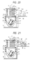
- Fig. 20 shows an eighth embodiment, which is a modified version of the fourth embodiment.
- a major difference from the fourth embodiment is that the inlet end of the tube is not fastened.
- a deflector roll 149 is provided directly above an optical fiber container 77 beside a bobbin.
- a guide roll 150 is disposed near the inlet end of the tube. The conveying force resulting from vibration pulls out the optical fiber 7 along the axis of a coil 9 thereof in the container 77. Supported and led by the deflector roll 149 and guide roll 150, the optical fiber 7 thus pulled out travels to the inlet end 3 of the tube.
- the deflector roll 149 and guide roll 150 whose function is not more than to support and guide the optical fiber 7, may be either rotatable or stationary.
- Fig. 21 shows a ninth embodiment, which is a modified version of the fifth embodiment.
- a major difference from the fifth embodiment is that the inlet end of the tube is not fastened.
- a roll feeder 110 is disposed next to a guide tube 107 fastened to the cover 79 of an optical fiber container 77 of the exit side thereof.
- the exit end of the roll feeder 110 is close to the inlet end of the tube.
- the roll feeder 110 has a gear motor 114 and a speed controller 115 of the type shown in Fig. 13.
- the passing operation can be carried out in the same way as with the foregoing embodiments. No preliminary insertion is needed.
- This apparatus permits pushing in the optical fiber 7 into the tube 1 as required. Or otherwise, a brake may be applied to the optical fiber 7 carried forward by the force of vibration. In the latter case, the braked optical fiber 7 in the tube 1 is pulled backward. The resulting reduction in undulation permits a stable insertion of the optical fiber 7 as described previously.
- Embodiments VIII and IX can be designed simply.
- Fig. 22 shows a last embodiment of this invention, which is a modified version of the fifth embodiment.
- a major difference from the fifth embodiment is that a second roll feeder is provided on the exit side of an optical fiber container to pull out an optical fiber therefrom.
- a second roll feeder 153, a second optical fiber feed condition sensor 155 and a support guide 157 are disposed between an optical fiber container 77 and a first roll feeder 110.
- the second roll feeder 153 and second optical fiber feed condition sensor 155 are of the same structure as the first roll feeder 110 and a first optical fiber feed condition sensor 47.
- the support guide 157 is of the same design as the support guide 54 shown in Fig. 1.
- the length of the support guide 157 is determined according to the distance between a bobbin 27 and an optical fiber container 77. For example, the optical fiber container 77 is separated from the bobbin 27 (by, for instance, 10 m), the length of the support guide 157 is increased accordingly.
- the second roll feeder 153 feeds the optical fiber 7 pulled out of the optical fiber container 77 to the first roll feeder 110.
- the optical fiber 7 is fed to the first roll feeder 110 in such a manner as to sag between the second roll feeder 153 and support guide 157. Consequently, no tension works on the optical fiber 7 while being fed to the first roll feeder 110.
- the second roll feeder 153 ensures the pull-out of the optical fiber 7 from the optical fiber container 77.
- a tube holder 124 holds the inlet end of the tube.
- the optical fibers were smoothly passed through the steel tubes without any hitch. It was confirmed that the optical fibers were passed through the entire length of the steel tubes within a given length of time at a speed of 2 m/min. to 4 m/min. No difficulty was encountered even in passing an optical fiber through a tube whose diameter is as small as 2 mm or less and whose length is as large as about 10 km. Of course, the optical fibers passed through the steel tubes suffered no degeneration.
- the feed roll feeder was always kept in motion.
- the speed of the drive roll was adjusted to control the feed of the optical fiber within the range of 40 % to 95 % of the conveyance speed owing to vibration. All this resulted in the attainment of an appropriate surplus length and the suppression of undulation, thereby assuring a smooth travel of the optical fiber through the steel tube.
- this invention is also applicable to the passing of othre types of threadlike pieces, such as wires of such metals as copper and steel and of such nonmetallic substances as plastics.
- the number of threadlike pieces passed through a tube is not limited to one. Multiple threadlike pieces may be passed through a tube if the inside diameter of the tube and the diameter of the threadlike piece permit this.
- the tube need not be of steel, but may be of many other types of materials, such as aluminum and synthetic resins. Any other subsequent process, such as surface polishing, may be added as desired to the passing of the threadlike piece through the metal tube.
- the central axis of the coil of the tube should preferably coincide with the central axis of a helix and extend vertically.
- other combinations of the spools, feeders, inlet end holders and means other than those disclosed hereabove are also included within the scope of this invention.
Landscapes
- Physics & Mathematics (AREA)
- General Physics & Mathematics (AREA)
- Optics & Photonics (AREA)
- Manufacturing Of Electric Cables (AREA)
- Guides For Winding Or Rewinding, Or Guides For Filamentary Materials (AREA)
- Feeding Of Articles To Conveyors (AREA)
- Jigging Conveyors (AREA)
Description
- This invention relates to a method and apparatus for passing threadlike pieces through tubular products, and more particularly to a method and apparatus for passing threadlike pieces through tubular products by vibration.
- The method and apparatus of this invention is used for making optical fiber cables, electric cables, composite conduits and the like comprising optical fibers, metal wires and other threadlike pieces passed through protective tubes or sheaths.
- Threadlike pieces are often passed through long tubular products. Optical fiber cables recently coming into extensive use, for example, are often metal-covered to make up for the insufficient strength of optical fibers. In such instances, core wires or cords of optical fibers are passed through tubes not more than a few millimeters in diameter and over several hundred meters in length. Sometimes, a messenger wire of steel or other metal is passed before a core wire or cord is passed.
- Typical conventional methods of making such products comprising threadlike pieces passed through metal and other tubes are disclosed in EP-A-0 091 717. In these methods, carrier members or tubes (hereinafter generically called tubes) through which threadlike peices are passed are vibrated. A threadlike piece is passed through a tube by means of the carrying force imparted thereto on the "vibrating conveyor". When a tube is as long as, for example, more than ten meters, the tube is coiled for ease in handling, and a threadlike piece is passed through the coiled tube.
- A threadlike piece passed through a long tube according to such conventional methods often stops halfway. The threadlike piece once stopped remains at a standstill even if the vibration of the tube continues. At the occurrence of such a blockage, the entire length of the inserted threadlike piece or a considerably larger portion thereof has had to be pulled out of the tube before starting the job all over again. As such, conventional methods of passing threadlike pieces through long tubes have been inefficient and time-consuming. The following is the cause of the halfway stopping of a threadlike piece in a tube the inventors have found.
- In the conventional methods, the inlet end of a tube vibrates integrally with a coil. The vibrating inlet end coming in contact with a threadlike piece exerts a force thereon that works in the direction of the diameter of the tube. Therefore, a portion of the threadlike piece upstream of and close to the inlet end of the tube moves vigorously in that direction. As a consequence, a centrifugal force flicks the portion of the threadlike piece near the inlet end out of the tube, thereby obstructing the further advance of the threadlike piece into the tube. Also, the rapid diametrical motion of the inlet end causes the same portion to remain ahead of the inlet end, thereby discharging the threadlike piece in the tube. Furthermore, the vibration repeatedly bends and damages the threadlike piece near the inlet end of the tube. Microcracks are a typical damage to optical fibers, in particular. The vibration-induced contact with the inlet end of the tube can produce an abrasion on the surface of the threadlike piece.
- Usually, a threadlike piece paid off from a spool or bobbin is fed into a tube into which the piece is to be passed. If the pay-off (or the feed) of the threadlike piece from the spool etc. lags, for some reason, behind the travel forward by vibration, the threadlike piece is pulled backward, no longer advancing into the tube.
- A threadlike piece winds forwards with undulating motion through a tube. The advance of the forward end of the threadlike piece lags behind that of the following portion or stops when the forward end trips against irregularities on the inner surface of the tube or foreign matter therein, or when it is subjected to a backward force from near the top surface of the inner wall. Pushed by the following portion, the forward end of the threadlike piece on such occasions suddenly makes heavy undulations. Consequently, peaks of such undulations in the foward end of the threadlike piece strike hard against the inner wall of the tube, offering enough resistance to suddenly disable the passing of the threadlike piece therethrough.
- The halfway stalling of a threadlike piece in a tube is due to either each or a combination of the three causes just described.
- EP-A-0 253 636 provides a method and apparatus for controlling the propulsive force on an optical transmission line member propelled along a tube by fluid drag.
- EP-A-0 108 590 provides an optical fiber transmission line and a method for installing optical fibers in ducts also by using the fluid drag of a gaseous medium to propel the fiber.
- The object of this invention is to provide a method and apparatus for efficiently passing a threadlike piece through a tube without damaging the threadlike piece. These object is solved by the features of the claims.
- In a method of passing a threadlike piece through a tube according to this invention the threadlike piece is fed in such a manner that the inlet end of the tube does not impart a radial motion to a portion of the threadlike piece upstream of and close to the inlet end.
- The threadlike piece is instead pulled out and fed from a coil thereof along the axis of the coil by a carrying force resulting from vibration that works on the threadlike piece in the tube. Also, the feed rate of the threadlike piece is adjusted at a point upstream of the inlet end of the tube so that the feed rate of the threadlike piece determines the passing rate thereof.
- A coil of tube is made by winding a tube around a cylindrical core such as a bobbin or a spool. A tube may instead by formed into a core-less coil. To facilitate passing and avoid the imposition of excessive bending stress of the threadlike piece, a coil of tube should preferably have a diameter of not smaller than 150 mm.
- A threadlike piece is fed from a spool on which the thread is wound, or a bobbin at a standstill, or a container holding a coil thereof. The spool may be rotated to permit a positive feed of a threadlike piece therefrom at a speed equivalent to that of conveyance owing to vibration. The feed rate of the threadlike piece, which determines the speed of the threadlike piece passed by vibration, is slower than the passing rate thereof. A feeder provided between the spool or the like and the inlet end of the tube controls the feed rate of a threadlike piece so that the feed rate determines the passing rate thereof. When a driven spool is used, the feed rate of the threadlike piece is adjusted by controlling the rotating speed of the spool. The feed rate may also be controlled by means of the friction between a threadlike piece and a guide to provide a support thereto that is provided upstream of the inlet end of a tube. For instance, the feed rate is decreased by increasing the friction therebetween. When the rotating speed of a spool is controlled and the friction of a guide is used, the feed rate of a threadlike piece cannot be made faster than the rate of conveyance by vibration. A threadlike piece may be inserted into the inlet end of a tube by means of a feeder either only during the early stage of passing or continuously throughout the entire period of passing. In the latter case, the feeder pushes a threadlike piece into a tube through the inlet end thereof, passing the threadlike piece therethrough. The feed rate of the threadlike piece is kept below the speed of conveyance by vibration.
- A coil of tube, which is either core-less or wound around a cylindrical core, can be vibrated by oscillating a member that holds or supports the coil by such known devices as a vibrating motor or an electromagnetic vibrator. The angle of vibration (i.e., the lead angle of helix), the frequency of vibration and the total amplitude of vibration in terms of vertical component are preferably between 5 degrees and 30 degrees, between 10 Hz and 30 Hz, and between 0.2 mm and 2.0 mm, respectively. An ultrasonic oscillator may be used, too.
- To ensure that the inlet end of a tube does not radially move a portion of a threadlike piece upstream of and close to the inlet end, the inlet end of the tube is immovable fastened to the floor or suitable structure or device therearound. Also, the inlet end of a tube may be held in such a manner as to allow the longitudinal motion of the tube while restraining the diametrical motion thereof.
- An apparatus for passing a threadlike piece through a tube according to this invention comprises a cylindrical member around which a tube through which a threadlike piece is to be passed is wound to form a coil thereof, a device to hold the inlet end of the tube so that the inlet end thereof does not radially move a portion of the threadlike piece upstream of and close to the inlet end of the tube, a device to vibrate the cylindrical member so that a given point of the tube reciprocates along a helical path, a device to feed the threadlike piece into the coil of tube being vibrated from one end thereof and a device for controlling the feed rate of the threadlike piece.
- The threadlike piece feeding device may be of such design as to control the feed rate of a threadlike piece at a point upstream of the inlet end of the tube so that the feed rate of the threadlike piece determines the passing rate thereof. Furthermore, the inlet end holding device and any of the threadlike piece holding devices just described may be combined into a single integral unit.
- When a coil of tube is vibrated by the method and apparatus of this invention just described so that a given point of the tube reciprocates along a helical path, the inner wall of the tube exerts on the threadlike piece in the coiled tube a force that works in a diagonally forward and upward direction. Therefore, this force causes the threadlike piece in the tube to jump or slide along the inner wall of the tube in a diagonally forward and upward direction. Thus, the inner wall of the tube intermittently exerts a carrying force, which works in the direction of the circumference of the coil, on the threadlike piece in the tube to cause the threadlike piece to advance therethrough.
- Since the inlet end of the tube is firmly held, no centrifugal force works on the threadlike piece near the inlet end. Therefore, the threadlike piece does not jump out of the tube. Saved from a sudden radial motion, in addition, the threadlike piece near the inlet end is neither caused to remain ahead of the inlet end nor damaged.
- When a threadlike piece to be fed to the tube is pulled out from a coil thereof along the axis of the coil, there is no need to rotate a spool and the coil wound therearound. Only a small amount of force is required for pulling out the threadlike piece from the coil. Therefore, the carrying force produced by vibration is enough for feeding the threadlike piece to the inlet end of the tube. The force to pull out the threadlike piece from the coil is not only small as mentioned above but also substantially constant. Such a force assures a stable feed of the threadlike piece to the inlet end of the tube, reducing the risk of the threadlike piece being passed stopping halfway.
- When the feed rate of a threadable piece determining the passing speed of the threadlike piece is faster than the speed of the threadlike piece passed forward by vibration, the threadlike piece is forced into the tube through the inlet end thereof. Vibration not only generates a carrying force, but also facilitates the insertion of the threadlike piece by reducing the friction between the threadlike piece and the inner surface of the tube. The force needed for the forcible insertion must be great enough to overcome the frictional resistance the inner surface of the tube offers to the threadlike piece travelling therethrough and, at the same time, small enough not to break the threadlike piece. A proper amount of pushing force permits the threadlike piece to be passed forward at a higher speed than the speed attained with the conveyance by vibration alone. Pushing with such a force is also an effective way to overpower the frictional resistance offered by the inner surface of the tube. Conceivably, on the other hand, frictional resistance increases with an increase in the length of a threadlike piece passed through a tube. Therefore, effectiveness of forcing the threadlike piece disappears beyond a certain point. As such, the choice of a proper pushing force and speed requires careful considerations on such points. Generally, the risk of stopping halfway is smaller with the forced-in threadlike piece. Because of the aforementioned limit in applicable length, however, this method is suited only for tubes not longer than several hundred meters. According to the present invention, the feed rate of a threadlike piece is slower than the speed of the threadlike piece and the threadlike piece in the tube is pulled backward. This backward pulling reduces the undulation of the threadlike piece in the tube. The lessened undulation, in turn, decreases or eliminates the friction between the inner surface of the tube and the leading end of the threadlike piece at the peak of undulation. This substantially totally eliminates the risk of halfway stopping.
- The method and apparatus of this invention assures efficient passing of a threadlike piece through a tube without causing degeneration and damage, even if the tube diameter is small (e.g., 2 mm or under in outside diameter) and the tube length is large (e.g., 1 km or over in overall length).
- Fig. 1 is a side elevation showing a first preferred embodiment of an optical fiber passing apparatus according to this invention;
- Fig. 2 is a plan view of a vibrating table of the same apparatus;
- Fig. 3 is a vertical cross-sectional view showing how the inlet end of a tube is fastened;
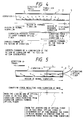
- Figs. 4 and 5 illustrate how an optical fiber is carried forward at the inlet end of a tube. Fig 4 shows a case according to this invention, whereas Fig. 5 a case with a conventional method;
- Fig. 6 is a side elevation showing a second embodiment of an optical fiber passing apparatus;
- Fig. 7 is side elevation showing a third embodiment of an optical fiber passing apparatus;
- Fig. 8 is a perspective view illustrating a method of forming a coil of optical fiber;
- Fig. 9(a) and 9(b) illustrate how an optical fiber is carried forward at the inlet end of a tube;
- Fig. 10 is a side elevation showing a fourth embodiment of an optical fiber passing apparatus
- Fig. 11 is a side elevation showing a fifth preferred embodiment of an optical fiber passing apparatus according to this invention;
- Fig. 12 is a plan view of a vibrating table of the apparatus shown in Fig. 11;
- Fig. 13 is a detail view of a roll feeder and a tube holder on the apparatus shown in Fig. 11;
- Fig. 14 illustrates how an optical fiber is carried forward at the inlet end of the tube on the apparatus shown in Fig. 11;
- Fig. 15 shows the condition of an optical fiber in the tube, with different surplus lengths;
- Fig. 16 is a side elevation showing a sixth embodiment of an optical fiber passing apparatus;
- Fig. 17 is a side elevation showing a seventh embodiment of an optical fiber passing apparatus;
- Fig. 18 is a perspective view of an optical fiber guide attached to a bobbin on the apparatus shown in Fig. 17;
- Fig. 19 illustrates how an optical fiber is carried foward at the inlet end of a tube on the apparatus shown in Fig. 17;
- Fig. 20 is a side elevation showing an eighth embodiment of an optical fiber passing apparatus;
- Fig. 21 is a side elevation showing a ninth embodiment of an optical fiber passing apparatus; and
- Fig. 22 is a side elevation showing a tenth preferred embodiment of an optical fiber passing apparatus according to this invention.
-
- In all embodiments of this invention to be described hereunder, an optical fiber is passed through a steel tube.
- A preferred embodiment of an apparatus to implement a passing method of this invention will be described first. Fig. 1 is an overall view of a passing apparatus according to this invention, and Fig. 2 is a plan view of a vibrating table on the same apparatus.
- A
base 11 is firmly fastened to thefloor 10 so as not to vibrate. Coil springs 18 to support a vibrating table are mounted at the four corners of the top surface of thebase 11. - A flat square vibrating table 14 is placed on the
base 11, with the support springs 18 interposed therebetween. Asupport frame 15 extends downward from the bottom surface of the vibrating table 14. - The
support frame 15 under the vibrating table 14 carries a pair of vibratingmotors motor 22 is placed diametrically opposite themotor 21 relative to the central axis C of the table 14. The rotating shafts of the vibratingmotors Unbalanced weights 24 are fastened to both ends of the rotating shafts of the vibratingmotors unbalanced weights 24 exerts a vibrating force on the vibrating table 14 that works aslant to the surface thereof. The paired vibratingmotors motors - Such vibrating means as those employing cranks, cams or electromagnets may be used in place of the vibrating
motors motors - A
bobbin 27 is fastened on the vibrating table 14 in such a manner that the axis thereof coincides with the central axis C of the vibrating table 14. Atube 1 through which anoptical fiber 7 is to be passed is coiled around thebobbin 27. Theoptical fiber 7 is fed into thetube 1 from the upper end of acoil 6 of the tube. To ensure that no excessive bending stress develops in the optical fiber, thecoil 6 of the tube should preferably have a diameter of not smaller than 150 mm. Theoptical fiber 7 used in this embodiment consists of an optical fiber precoated with resin. Thetube 1 is a steel tube. The outer periphery of thebottom flange 29 of thebobbin 27 is fastened to the vibrating table 14 withfastening jigs 31 so that the vibration of the vibratingmotors bobbin 27 has a groove (not shown) cut around the circumference thereof, with successive ridges and recesses pointing to the axis thereof. The groove is designed so that thetube 1 comes inclose contact therewith. - A
feed spool 34, which constitutes anoptical fiber feeder 33, is placed beside thebobbin 27. Thefeed spool 34 is rotatably supported on abearing stand 35. Thefeed spool 34 pays off theoptical fiber 7 wound therearound to the flaredinlet end 3 of the tube. - A
drive motor 38 is provided next to thefeed spool 34. Thefeed spool 34 and drivemotor 38 are interlocked through abelt transmission 40. Rotated by thedrive motor 38, thefeed spool 34 pays off theoptical fiber 7 to thetube 1 wound around thebobbin 27. - A
cylindrical support guide 43 is provided near the point where thefeed spool 34 pays off an optical fiber. Thesupport guide 43 supports theoptical fiber 7 paid off from thefeed spool 34. - An optical fiber
feed condition sensor 47 is installed downstream of thesupport guide 43. The optical fiberfeed condition sensor 47 comprises asupport column 48 and an opticalfiber level sensor 49 attached thereto. Tho opticalfiber level sensor 49 comprises an image sensor and an oppositely disposed light source. Installed in the pass line of theoptical fiber 7, the opticalfiber level sensor 49 senses the sagging condition thereof. A CCD line sensor is used as the image sensor. - To the optical fiber
feed condition sensor 47 is connected arotation speed controller 52 that controls the voltage of apower supply 39 to saiddrive motor 38 on the basis of signals from the optical fiberfeed condition sensor 47. The rotation speed of thedrive motor 38 or, in other words, the pay-off speed of theoptical fiber 7 is controlled according to the level at which theoptical fiber 7 interferes with the travel of the light from the light source in the opticalfiber level sensor 49. - The speed with which the
optical fiber 7 is passed through thetube 1 is not always constant but may vary when resonance occurs or depending on the surface condition of the inner wall of thetube 1 and theoptical fiber 7. A change in the running speed of theoptical fiber 7 in thetube 1 affects the feeding condition of theoptical fiber 7 on the outside. If the feed speed fails to follow the passing speed, theoptical fiber 7 may either sag excessively or overstretch and break, hindering smooth feeding of theoptical fiber 7. But the feed speed of theoptical fiber 7 can always be kept within the desired range by varying or stopping the rotation of thefeed spool 34 depending on the travelling condition of theoptical fiber 7 in thetube 1. Then, theoptical fiber 7 is kept in the optimum condition (with a slight sagging as shown in Fig. 1), without oversagging or overstretching. Consequently, theoptical fiber 7 is passed through thetube 1 without a hitch, with no load imposed thereon or no resistance offered to the passage thereof. Incidentally, an optical fiber 0.4 mm in diameter does not go into a steel tube having an inside diameter of 0.5 mm if a force of 20 gf or greater works thereon in a direction opposite that of feeding. - A
cylindrical support guide 54 and anelectromagnetic feeder 55 are provided on the exit side of the optical fiberfeed condition sensor 47. Theelectromagnetic feeder 55 sends anoptical fiber 7 from thesupport guide 54 to the flaredend 3 of the tube. - The inlet and outlet of the support guides 43 and 54 should preferably have a smooth curved surface. The support guides 43 and 54 must be made of such materials as glass and plastic whose coefficient of friction is low enough to assure a smooth travel of the
optical fiber 7. Provision may be made to supply such a solid lubricant as a powder of carbon, talk, molybdenum disulfide, etc. to the surface of theoptical fiber 7 travelling through the support guides 43, 54. - A
metal tube holder 57 is provided on the exit side of theelectromagnetic feeder 55. The inside of themetal tube holder 57 is funnel-shaped as shown in Fig. 3. - Now a method of passing an
optical fiber 7 through atube 1 using the above-described apparatus will be described. - A
coil 6 is formed in advance by winding atube 1 around abobbin 27. Thetube 1 wound around thebobbin 27 need not always be in a single ring, but in multiple rings. In a coil of multiple rings, the first ring fits closely in a groove cut in the surface of thebobbin 27. The second and subsequent rings are arranged to fit in the recesses formed between the turns of thetube 1 of the preceding ring. Then, thebobbin 27 carrying thewound tube 1 is fastened on the vibrating table 14 in such a manner that the axis of the coil coincides with the central axis C of the vibrating table 14. - A ring of the tube, making up the lead-in
section 2 thereof, is unwound from the coil and cut to a suitable length. This cutoff length of the tube is curved in a horizontal plane. Then, theinlet end 4 of the tube passed through aguide hole 58 in themetal tube holder 57 is flared into a funnel-shape, and fastened to themetal tube holder 57 with ametal fastener 59. Theremotest end 5 of the lead-insection 2 is fastened to theflange 29 of thebobbin 27 with ametal fastener 61. - An
optical fiber 7 consisting of a precoated fiber, is wound around thefeed spool 34. Theleading end 8 of theoptical fiber 7 pulled out of thefeed spool 34 is inserted through themetal tube holder 57 into theinlet end 4 of the tube, after passing through thesupport guide 43, optical fiberfeed condition sensor 47,support guide 54 andfeeder 55. - The
drive motors feeder 55 and thedrive motor 38 of thefeed spool 34 are started in that order. - With the
drive motors bobbin 27 and thecoil 6 of tube to the lead-insection 2 thereof. - Referred now to Figs. 3 and 4 (in Fig. 4, the curved lead-in
section 2 of the tube is shown as a straight tube for convenience's sake), how theoptical fiber 7 enters thetube 1 when the passing operation is started will be explained. The lead-insection 2 has a midway transition point T where the direction of vibration coincides with the direction to the center of curvature of theinlet 2. In the section (hatched in Fig. 3) between the flaredend 3 and the transition point T, vibration transmitted from the inner wall of the tube to theoptical fiber 7 produces no conveying force. In this section, the pushing force of thefeeder 55 sends the leading end of theoptical fiber 7 forward. Also in this section, vibration keeps theoptical fiber 7 from sliding along the inner wall of the tube, reduces the friction between theoptical fiber 7 and the inner wall of the tube, and facilitates the forward motion of the leading end of theoptical fiber 7 pushed by thefeeder 55. - In the section between the transition point T and the
remotest end 5 of the lead-insection 2 end, the conveying component of vibration increases progressively. Theoptical fiber 7 before this section, or between the flaredend 3 and the transition point T, is inside the tube and under the influence of the driving force of thefeeder 55. Therefore, no force to prevent advance (owing to both the effect of centrifugal force and the static inertia of the optical fiber behind) works on the leading end of theoptical fiber 7 in this section. As such, the leading end of theoptical fiber 7 advances if the vibrating tube exerts any conveying force at all on the optical fiber 7 (or if the angle between the directions of vibration and passing is acute). The conveying force resulting from vibration carries theoptical fiber 7 forward after the leading end thereof has passed the transition point T. When the leading end reaches theremotest end 5 of theinlet 2, theremotest end 5 lies at the uppermost end of thecoil 6, with theoptical fiber 7 passed into thetube 1 substantially along a line tangent to thecoil 6. Once theoptical fiber 7 has thus been properly passed into thetube 1, the rotation of thefeeder 55 is stopped. Afterward, thefeeder 55 serves as a holding guide. - With the technology disclosed in EP-A-91717, incidentally, the leading end of an optical fiber is inserted by a given distance L before passing is started, as shown in Fig. 5. Accordingly, conveying force produced by vibration must be exerted on the
optical fiber 7 at the flaredend 3 to make the conveying force great enough to overcome a force owing to the effect of centrifugal force and a force owing to the static inertia of theoptical fiber 7 behind theinlet end 3. The conveying force resulting from vibration becomes equal to the combined force to prevent the advance of the optical fiber at point P. Said distance L is greater than the distance between point P and the flaredend 3 of the tube. The optical fiber does not advance while the leading end thereof stays upstream of point P. It is not until the leading end has passed point P that the optical fiber begins to move forward. - As is obvious from Figs. 4 and 5, the conventional method inserts a considerable length of optical fiber into the tube before starting passing. By contrast, the preferred embodiment of this invention being described does not require such preliminary insertion.
- Driven by a component of the force exerted by the inner wall of the
tube 1 which works in the circumferential direction of the coil, theoptical fiber 7 in thecoil 6 of the tube moves further into the tube. Because the axis of the coil coincides with the central axis C of the vibrating table 14, theoptical fiber 7 in the tube moves in a circle about the central axis C (in the clockwise direction in the embodiment shown in Fig. 2). - Reference is now made back to Fig. 1.
- When the helical vibration is transmitted through the vibrating table 14 to the
coil 6 of the tube, theoptical fiber 7 fed from the flaredend 3 of the tube above thecoil 6 continuously moves forward through thetube 1. That is, the vibration of thecoil 6 moves theoptical fiber 7 paid off from thefeed spool 34 forward through thesupport guide 43, optical fiberfeed condition sensor 47,support guide 54,feeder 55, flaredend 3 of the tube,inlet 2, coil-formedtube 1, and outlet end of the tube. Thus, theoptical fiber 7 is passed through the entire length of thecoil 6 of the tube in a given time. Because theinlet end 4 the tube is fastened, the flaredend 3 causes no damage to theoptical fiber 7. - Any variation in the passing speed of the
optical fiber 7 affects the feed condition thereof at the point where the opticalfiber level sensor 49 is installed, with the resulting change in the feed condition being instantly detected by the opticalfiber level sensor 49. If the opticalfiber level sensor 49 senses that theoptical fiber 7 is overstretched, a corresponding signal will be sent to thedrive motor 38 to increase the rotation speed of thefeed spool 34, thereby increasing the feed speed of theoptical fiber 7. If an excessive sagging of theoptical fiber 7 is sensed, thedrive motor 38 will be controlled to slow down the feed speed of theoptical fiber 7. In this way, any abnormal condition in the forward travel of the optical fiber is instantly sensed, corrected and returned to the normal condition. - Fig. 6 shows another embodiment. In all of the following embodiments, the devices and members similar to those shown in Figs. 1 to 3 will be designated by the same reference numerals, with detailed description thereof being omitted.
- In this second embodiment, the
optical fiber 7 paid off from thecoil 9 thereof drops into the lead-insection 2 of the tube under its own weight. - A
frame 64 is fastened diagonally to thefloor 10 above a vibrating table 14. Abobbin 66 around which anoptical fiber 7 is wound is placed on theframe 64. - An
optical fiber guide 68 is provided next to theframe 64. Theoptical fiber guide 68 has aguide tube 70 supported by abracket 69. Theguide tube 70 consists of avertical portion 71 and acurved portion 72 curved diagonally downward. The upstream end of thecurved portion 72 of theguide tube 70 opens diagonally downward. The surface of theframe 64 on which the bobbin is placed is tilted so that the axis of the coil of the optical fiber faces the opening of thecurved portion 72 of theguide tube 70. - A
metal tube holder 74 is provided next to theoptical fiber guide 68 on the exit side thereof. Themetal tube holder 74 has a throughhole 75. Because theend 3 of the tube passed through the throughhole 75 is flared, theinlet end 4 of the tube is firmly held in the throughhole 75. As such, theinlet end 4 of the tube held by themetal tube holder 74 does not move, either diametrically or longitudinally. - The
tube 1 is wound around thebobbin 27 to form acoil 6 of the tube, with the last ring thereof fastened with anadhesive tape 30. The lead-insection 2 of a given length is unwound from the coil, curved upward and extended. Theinlet end 4 is fastened to themetal tube holder 74. Acoil 9 of theoptical fiber 7 is as wound at the fiber manufacturer. The forward end of theoptical fiber 7 paid off from thebobbin 66 is passed into theinlet end 4 through theguide tube 70. Then, drivemotors optical fiber 7 wound into thecoil 9. - The
optical fiber 7 falls under gravitation through thevertical portion 71 of theguide tube 70 and the lead-insection 2 of thetube 1. As such, this embodiment reduces the load to be born when theoptical fiber 7 is unwound from thecoil 9 and the length of theoptical fiber 7 to be passed in initially. - Fig. 7 shows a third embodiment. In this embodiment, the inlet end of a tube is held in such a manner as not to permit diametrical motion alone. Longitudinal motion is permitted. Also, a feeder is provided to push an optical fiber into the tube, which permits passing the optical fiber through the tube at a speed faster than the speed of conveyance by vibration. But this embodiment is not applicable to longer tubes whose length exeeeds several hundred meters because of the limit in the passable length of the optical fiber mentioned previously.
- As shown in the figure, an
optical fiber container 77 is provided beside thebobbin 27. Theoptical fiber container 77 consists of a cylindrical container proper 78 having an open top. Thecontainer 77 contains anoptical fiber 7 is fed into the container proper 78 that is mounted and rotated on the turn table (not shown), as will be described later. - An
optical fiber guide 81 is disposed next to theoptical fiber container 77. Theoptical fiber guide 81 has aguide tube 83 supported on astand 82. The downward-curved inlet end of theguide tube 83 opens toward theoptical fiber container 77 substantially on the central axis thereof. - A
belt feeder 86 is disposed on the exit side of theoptical fiber guide 81. Thebelt feeder 86 comprises a pair ofendless belts 88, one lying on top of the other, on a table 87. Driven by motor-poweredpulleys 89, thebelts 88 send theoptical fiber 7 from theoptical fiber guide 81 held therebetween to theinlet end 4 of the tube. - A cylindrical metal tube holder 92 is placed on the exit side of the
belt feeder 86. Theinlet end 4 of the tube is passed through the metal tube holder 92 whose inside diameter is somewhat larger than the outside diameter of thetube 1. Though allowed to slide longitudinally, theinlet end 4 of the tube is not permitted to move radially, i.e., up and down and sideways. - The following is a method of passing an
optical fiber 7 through atube 1 using the above-described apparatus. - While a
coil 6 of the tube is formed, acoil 9 of theoptical fiber 7 is formed inside theoptical fiber container 77 by laying up piles thereof. Abobbin 27 carrying a coil of thetube 1 is fastened to a vibrating table 14 with a throughbolt 32. Theoptical fiber 7 is pulled up above theoptical fiber container 77, proceeding downward from the uppermost loop of thecoil 9. On this occasion, each loop of theoptical fiber 7 is twisted 360 degrees maximum. To regain the original condition, the twisted optical fiber warps inside thetube 1, offering a resistance to conveyance. Therefore, a reversed twist should preferably be given to theoptical fiber 7 when it is fed into thecontainer 77 so that the twist that theoptical fiber 7 receives on being unwound is offset. The optical fiber thus kept in a container does not curl like the one wound around a spool or the like. - Fig. 8 shows a method of giving a reversed twist to an
optical fiber 7. Theoptical fiber 7 is fed through aguide tube 95,caterpillar feeder 95 and arotating guide tube 97 into the container proper 78 of theoptical fiber container 77. Therotating guide tube 97 is eccentric to the container proper 78 by δ, and rotated by a motor (not shown) through agear transmission 98. The container proper 78 and therotating guide tube 97 are rotated in the same direction, about the central axes X and Y thereof. Fed from therotating guide tube 97, theoptical fiber 7 is circumferentially piled up from the bottom of the container proper 78 to form a coil, becoming progressively eccentric by a width of 2δ. If the rotating speed of the container proper 78 is VP and that of therotating guide tube 97 is VG, the angle of a reversed twistrotating guide tube 97, the angle of the reversed twist becomes substantially equal to 360 degrees. Therefore, theoptical fiber 7 forms no kink when unwound from thecoil 9. - Then, a given length of the
optical fiber 7 taken out of thecontainer 77 is passed through theoptical fiber guide 81, thebelt feeder 86 and the flaredend 3 of the tube until theleading end 8 of theoptical fiber 7 enters thetube 1. - When preparations for passing are completed, the vibrating
motors belt feeder 86 are started. - Referring now to Figs. 9(a) and 9(b), the advance of the
optical fiber 7 into thetube 1 will be described. Because the metal tube holder 92 firmly holds theinlet end 4, the lead-insection 2 does not move up and down and sidewise, though vibrating longitudinally. Therefore, no driving force f owing to vibration works on theoptical fiber 7 at the lead-insection 2 of thetube 1. The advance of theoptical fiber 7 in this region is solely due to the pushing force F exerted by thebelt feeder 86. - In the
coil 6 of thetube 1 lying beyond theremotest end 5 of the lead-insection 2, thetube 1 vibrates helically, with the inner wall thereof pushing theoptical fiber 7 diagonally up and foward. Therefore, theoptical fiber 7 jumps, or slides along the inner wall of the tube, diagonally forward. Thus, a circumferential component of the force exerted by the inner wall of thetube 1 and a pushing force exerted by thebelt feeder 86, in combination, cause theoptical fiber 7 to travel forward in the tube. That is, the two forces produced by vibration and exerted by the feeder move theoptical fiber 7 forward through the tube. - The
optical fiber 7 pushed by thebelt feeder 86 into the flaredend 3 of the tube will encounter the following resistance: - (a) Resistance that the friction with the tube wall offers to forward travel;
- (b) Resistance that the coiled tube offers to forward travel;
- (c) Resistance that the kinked optical fiber offers to forward travel; and
- (d) Backward force from near the top of the inner wall of the tube.
-
- Resistance (b) and (c) work to increase the frictional resistance (a).
- Because resistance (b) is greater in the coiled
tube 1 than in a straight tube, transmission of the pushing force from the flaredend 3 throughout the entire length of the optical fiber is not as easy. However, the helical vibration of thecoil 6 produces an equal (uniform) vibration at all points of thetube 1. The vibration is a simple harmonic motion slanting in the longitudinal direction of the tube, having a horizontal component tangential to thecoil 6 of the tube and exerting a driving force f on theoptical fiber 7. The driving force f works tangentially to thecoil 6 of the tube at all points thereof. Therefore, the driving force f always works on theoptical fiber 7 in thetube 1 in the longitudinal direction thereof or in the direction of travel. Working along the curve of the tube, the driving force f reduces the friction owing to vibration and keeps theoptical fiber 7 from being pressed against the tube wall. In other words, the driving force f works to keep theoptical fiber 7 from getting out of the right path. Theoptical fiber 7 pushed by force F into the curved tube from the flaredend 3 moves forward as if it was traveling through a straight tube under the influence of the driving force f. The vibration of thetube 1, of course, reduces the friction between the optical fiber and the tube wall. The method of this invention, therefore, overcomes the resistance (a) from the friction with the tube wall by vibration and the resistance (b) owing to thecurved tube 1 by a combination of vibration and the driving force f. Keeping theoptical fiber 7 in the tube from sagging, the driving force f assures easier transmission of the pushing force F throughout the entire length of the optical fiber. The resistance (c) owing to the kink of the optical fiber can also be overcome by feeding a pre-twistedoptical fiber 7 from acoil 9 held in theoptical fiber container 77. Theoptical fiber 7 kept in this condition has no tendency to kink. The frictional resistance (a) from the tube wall can be reduced by applying a lubricant on the surface of the optical fiber, too. The resistance (b) owing to the curved tube can also be reduced by increasing the coil diameter. - Allowed to move in the longitudinal direction of the
tube 1, theinlet end 4 thereof is less subjected than otherwise to the repeated bending force exerted by the vibratingtube 1, thus remaining undamaged. - Fig. 10 shows still another embodiment. invention. In this embodiment, the inlet end of the tube is firmly held. A conveying force resulting from vibration pulls out an optical fiber from a coil thereof.
- An
optical fiber container 77 and anoptical fiber guide 81 are placed beside abobbin 27. - A
tube holder 101 stands next to theoptical fiber guide 81 on the exit side thereof. Thetube holder 101 has acasing 103 supported by astand 102, withguide rolls 104 rotatably set in thecasing 102. The guide rolls 104 are paired in such as manner as to hold atube 1 therebetween. The pairs of guide rolls are alternately set in the vertical and horizontal positions. As such, theinlet end 4 of the tube held by thetube holder 101 is allowed to move longitudinally, but not radially. - By winding a
tube 1 around thebobbin 27, acoil 6 of the tube is formed in advance. A ring of thetube 1 making up the lead-insection 2 thereof is then unwound from thecoil 6 and cut to a suitable length. The lead-insection 2 of thetube 1 is then pulled from thecoil 6 to thetube holder 101. After theinlet end 4 has been passed through thetube holder 101, theforemost end 3 of the tube is flared into a funnel-like shape. Theremotest end 5 of the lead-insection 2 is immovably fastened to theflange 29 of thebobbin 27 with ametal fastener 61. Anoptical fiber 7 is placed in theoptical fiber container 77. - A given length of the
optical fiber 7 unwound from thecoil 9 in thecontainer 77 is passed into thetube 1 through anoptical fiber guide 81 and the flaredend 3 thereof. Because only theleading end 8 of theoptical fiber 7 is inserted in thetube 1, the conveying force the vibratingtube 1 exerts on theoptical fiber 7 is limited to the lead-insection 2 of the tube. Accordingly, the conveying force is too small to unwind from thecoil 9 and carry to the flaredend 3 that portion of theoptical fiber 7 which follows the lead-insection 2. The length of the preliminarily inserted optical fiber is between a few meters and ten-plus meters, varying with the size and surface condition of thetube 1 andoptical fiber 7 and the condition of thecoil 9 of theoptical fiber 7. A pull force on the order of several tens of grams works on theoptical fiber 7 as a result of the preliminary insertion. The preliminary insertion is done either manually or by feeding through pinch rolls. - When preparations for passing are complete, drive
motors optical fiber 7 unwound from thecoil 9 in theoptical fiber container 77 continuously moves into thetube 1 through the flaredend 3 thereof. - Figs. 11 and 12 show another embodiment of this invention.
- A
guide tube 107 is fastened to thecover 79 of anoptical fiber container 77. Theguide tube 107 extends from the top of thecontainer 77 to aroll feeder 57. - A
roll feeder 110 is disposed on the exit side of theguide tube 107. As shown in Fig. 13, theroll feeder 110 has adrive roll 112 rotatably set in ahousing 111. Thedrive roll 112 is rotated by agear motor 114 whose speed, in turn, is controlled by aspeed controller 115. Anarm 117 is connected to thehousing 111 by means of apin 118. Thearm 117 carries a rotatably mounted hold-down roll 120 at the tip thereof. Thearm 117 is manually rotated about thepin 118 to bring the hold-down roll 120 into and out of contact with thedrive roll 112. Thedrive roll 112 and hold-down roll 120 are respectively covered withrubber tires drive roll 112 and hold-down roll 120 hold theoptical fiber 7 from theguide tube 107 under the weight of the hold-down roll 120. The rotation of thedrive roll 112 sends theoptical fiber 7 into theinlet end 4 of the tube. - A
tube holder 124 is disposed on the exit side of theroll feeder 110, with an optical fiberfeed condition sensor 47 placed therebetween. As shown in Fig. 13, thetube holder 124 comprises anouter cylinder 124, an intermediate cylinder 125 and aninner cylinder 127. Astand 129 fastens the outer cylinder 125 to thefloor 10. A number ofrotatable balls 130 are fitted on the intermediate cylinder 126. Theballs 130 projecting on both sides of the intermediate cylinder 126 are in contact with the inner surface of the outer cylinder 125 and the outer surface of theinner cylinder 127. Therefore, theinner cylinder 127 is allowed to rotate and move axially, but not permitted to move radially. Atop ring 131 is fitted near each end of theinner cylinder 127 to prevent the disengagement thereof from the outer cylinder 125. - The
inlet end 4 of the tube is inserted in theinner cylinder 127 of thetube holder 124 and fastened with asetscrew 132. Theroll feeder 110 pulls out the looped upoptical fiber 7 from the top end thereof. Theoptical fiber 7 is then fed into thetube 1 through theguide tube 107,roll feeder 110, optical fiberfeed condition sensor 47 andtube holder 124. - Referring to Fig. 14, the advance of the
optical fiber 7 into thetube 1 immediately after the start of insertion will be described now. Near the flaredend 3, thetube 1 is allowed to move only axially, not radially. Therefore, the inner wall of the vibrating tube exercises no conveying force on theoptical fiber 7 in this region. But theroll feeder 110 advances theleading end 8 of theoptical fiber 7. The vibration of the tube also reduces the friction between theleading end 8 of theoptical fiber 7 and the inner wall of the tube, thereby facilitating the action of theroll feeder 110 to advance theleading end 8 of theoptical fiber 7. - In a positive vibration area following the area in which radial vibration is inhibited, the radial component of vibration increases progressively. No force to check advance (owing to the centrifugal effect and the static inertia of the optical fiber behind) works on the leading end of the
optical fiber 7 in this region because theoptical fiber 7 in the upstream radial vibration inhibited area is inside the tube and, in addition, under the influence of the driving force exerted by theroll feeder 110. Accordingly, the conveying force owing to vibration causes theoptical fiber 7 to advance when the leading end thereof enters the positive vibration area. When the leading end of theoptical fiber 7 reaches theremotest end 5 of the lead-insection 2 of the tube, theremotest end 5 is at the uppermost end of thecoil 6 of the tube. Thus, theoptical fiber 7 is passed into thetube 1 substantially tangentially to thecoil 6. When theoptical fiber 7 has thus been properly brought into the regular passing position, thedrive roll 112 of theroll feeder 110 is stopped, with the hold-down roll 120 retracted above away from the optical fiber. After this, thedrive roll 112 serves as a guide to hold the optical fiber. - In the above example, the
drive roll 112 of theroll feeder 110 was stopped and functionally switched into a holding guide after theoptical fiber 7 has been brought into the passing position. According to the present invention thedrive roll 112 may instead be allowed to continue driving even in that state. In this instance, the feed rate of the optical fiber is adjusted so that the speed with which theoptical fiber 7 is fed to the flaredend 3 of the tube is below the speed of theoptical fiber 7 conveyed by the action of vibration. That is, theroll feeder 110 exerts a braking force on theoptical fiber 7 being passed into thetube 1. This permits adjusting the surplus length of theoptical fiber 7 in thetube 1. The surplus length increases as the feed rate of the optical fiber becomes closer to the speed of theoptical fiber 7 conveyed forward by helical vibration, and vice versa. By the same method, the undulation of the optical fiber passed through the tube can be reduced, too. The less the undulation, the fewer will be the chances of the optical fiber coming in contact with the top surface of the inner wall of the tube. Then, the optical fiber is passed forward more smoothly. - The
optical fiber 7 passed into thetube 1 must have a proper surplus length. Fig. 15(a) shows anoptical fiber 7 with an insufficient surplus length. Such an optical fiber involves the risk of breaking, unable to follow an elongation that might occur when temperature changes. Fig. 15(b) shown an optical fiber with a proper surplus length. Fig. 15(c) shows an optical fiber with an excess surplus length. Such an optical fiber bends more, receives greater pressure from the tube wall and, thus, travels forward less smoothly. An appropriate surplus length can be obtained by adjusting the feed rate of the optical fiber as described above. - An
optical fiber 7 being passed into atube 1 may sag between theroll feeder 110 andtube holder 124. On detecting a sag, the optical fiberfeed condition sensor 47 sends a signal to decelerate thedrive roll 112 of theroll feeder 110, thereby eliminating the sag. Thedrive roll 112 stops when the sagging of theoptical fiber 7 exceeds a preset limit. - Fig. 16 shows still another embodiment.
- This embodiment is a modified version of the embodiment II shown in Fig. 6. This embodiment differs from the embodiment II in Fig. 6 in that the inlet end of the tube is longitudinally movable and that the
optical fiber 7 from afeed spool 34 is directly fed to aguide tube 135. Part of thefeed spool 34 on anoptical fiber feeder 33 projects forward from thefloor 10, with thestraight guide tube 135 vertically disposed directly thereunder. In this embodiment, the rotating speed of thefeed spool 34 is adjusted so that the feed rate of theoptical fiber 7 to theinlet end 3 of the tube is below the speed with which the optical fiber is conveyed forward by the action of vibration. An optical fiber feed condition sensor of the type described above may be installed to detect the sagging of theoptical fiber 7. Then, the rotation of thefeed spool 34 may be either decelerated or stopped according to the amount of sagging detected. - Fig. 17 shows a seventh embodiment.
- An
optical fiber feeder 33 and an optical fiberfeed condition sensor 47 are disposed diagonally above abobbin 27. Abend 138 is provided on the exit side of the optical fiberfeed condition sensor 47. Thebend 138 leads theoptical fiber 7 from the optical fiberfeed condition sensor 47 to anoptical fiber guide 140. The inlet and outlet ends of thebend 138 should preferably have a smoothly machined curved surface. To ensure that the falling of theoptical fiber 7 under gravity is not inhibited, thebend 138 must be made of material with a low coefficient of friction such as glass and plastics. - An optical
fiber intake guide 140 is disposed directly below thebend 138. Themain portion 141 of theintake guide 140 is shaped like a trumpet as shown in Fig. 18, having aslit 142 that opens upward. Theintake guide 140 is suspended from thetop flange 29 of thebobbin 27 by means of ametal holder 144. - Provision may be made in the
bend 138 or opticalfiber intake guide 140 to apply a solid lubricant, such as a powder of carbon, talc, and molybdenum disulfide on the surface of theoptical fiber 7 passing therethrough. - In this apparatus, the
inlet end 4 of the tube is fastened to thetop flange 29 of thebobbin 27 with ametal fastener 146. Then, the smaller-diameter end of the intake guide proper 141 is connected to thetip 3 of the tube. Referring now to Figs. 18 and 19, the forward motion of theoptical fiber 7 at the inlet of thetube 1 will be described. Theoptical fiber 7, fed from theoptical fiber feeder 33 to thebend 138, falls through theslit 142 into the opticalfiber intake guide 140 under its own weight. The opticalfiber intake guide 140 vibrates together with thecoil 6 of the tube. Therefore, theoptical fiber 7 in theintake guide 140 enters the tube from the lead-insection 2 thereof, under the influence of the conveying force produced by the vibration V of the inner wall of the guide. Theslit 142 in theintake guide 140 has a width such that theedges 143 thereof remain out of contact with theoptical fiber 7 fed from above even when theguide 140 vibrates together with thebobbin 27. Therefore, theoptical fiber 7 does not spring out from theinlet end 3 of the vibrating tube. - Fig. 20 shows an eighth embodiment, which is a modified version of the fourth embodiment. A major difference from the fourth embodiment is that the inlet end of the tube is not fastened.
- A
deflector roll 149 is provided directly above anoptical fiber container 77 beside a bobbin. Aguide roll 150 is disposed near the inlet end of the tube. The conveying force resulting from vibration pulls out theoptical fiber 7 along the axis of acoil 9 thereof in thecontainer 77. Supported and led by thedeflector roll 149 and guideroll 150, theoptical fiber 7 thus pulled out travels to theinlet end 3 of the tube. - With the apparatus just described, the passing operation can be carried out in the same way as with the foregoing embodiments, except that preliminary insertion is indispensable. The
deflector roll 149 and guideroll 150, whose function is not more than to support and guide theoptical fiber 7, may be either rotatable or stationary. - Fig. 21 shows a ninth embodiment, which is a modified version of the fifth embodiment. A major difference from the fifth embodiment is that the inlet end of the tube is not fastened.
- A
roll feeder 110 is disposed next to aguide tube 107 fastened to thecover 79 of anoptical fiber container 77 of the exit side thereof. The exit end of theroll feeder 110 is close to the inlet end of the tube. Though not shown, theroll feeder 110 has agear motor 114 and aspeed controller 115 of the type shown in Fig. 13. - With the apparatus just described, the passing operation can be carried out in the same way as with the foregoing embodiments. No preliminary insertion is needed. This apparatus permits pushing in the
optical fiber 7 into thetube 1 as required. Or otherwise, a brake may be applied to theoptical fiber 7 carried forward by the force of vibration. In the latter case, the brakedoptical fiber 7 in thetube 1 is pulled backward. The resulting reduction in undulation permits a stable insertion of theoptical fiber 7 as described previously. - Embodiments VIII and IX can be designed simply.
- Fig. 22 shows a last embodiment of this invention, which is a modified version of the fifth embodiment. A major difference from the fifth embodiment is that a second roll feeder is provided on the exit side of an optical fiber container to pull out an optical fiber therefrom.
- As shown in the drawing, a
second roll feeder 153, a second optical fiberfeed condition sensor 155 and asupport guide 157 are disposed between anoptical fiber container 77 and afirst roll feeder 110. Thesecond roll feeder 153 and second optical fiberfeed condition sensor 155 are of the same structure as thefirst roll feeder 110 and a first optical fiberfeed condition sensor 47. Thesupport guide 157 is of the same design as thesupport guide 54 shown in Fig. 1. The length of thesupport guide 157 is determined according to the distance between abobbin 27 and anoptical fiber container 77. For example, theoptical fiber container 77 is separated from the bobbin 27 (by, for instance, 10 m), the length of thesupport guide 157 is increased accordingly. - The
second roll feeder 153 feeds theoptical fiber 7 pulled out of theoptical fiber container 77 to thefirst roll feeder 110. Theoptical fiber 7 is fed to thefirst roll feeder 110 in such a manner as to sag between thesecond roll feeder 153 andsupport guide 157. Consequently, no tension works on theoptical fiber 7 while being fed to thefirst roll feeder 110. Thesecond roll feeder 153 ensures the pull-out of theoptical fiber 7 from theoptical fiber container 77. In this embodiment, atube holder 124 holds the inlet end of the tube. - In order to confirm the effect of this invention, an optical fiber was passed through a steel tube, using the apparatus shown in Fig. 11, under the following conditions:
- (1) Test Specimens
- Coils of steel tubes:
- Seven different coils (having 10 to 20 layers of rings), each being orderly wound around a steel bobbin having a barrel diameter of 1200 mm, of seven different steel tubes 10km in length, having an outside diameter of 0.8 mm to 2.0 mm and an inside diameter of 0.5 mm to 1.6 mm.
- Optical fibers:
- Quartz glass optical fiber (125 µm in diameter) coated with silicone resin, having a diameter of 0.4 mm.
- (2) Vibrating Condition
- Having 10 to 20 layers of rings, each coil of the steel tube tested vibrated substantially equally at all points thereof.
- Angle of vibration with respect to the horizontal plane of the coil: 15 degrees
- Frequency of vibration: 20 Hz
- Vertical component of total amplitude: 1.25 mm - 1.55 mm
- (3) Roll Feeder When the optical fiber has been put in the steady passing condition, the drive roll of the roll feeder is stopped to function as an optical fiber support guide, with the hold-down roll retracted.
-
- Under the above conditions, the optical fibers were smoothly passed through the steel tubes without any hitch. It was confirmed that the optical fibers were passed through the entire length of the steel tubes within a given length of time at a speed of 2 m/min. to 4 m/min. No difficulty was encountered even in passing an optical fiber through a tube whose diameter is as small as 2 mm or less and whose length is as large as about 10 km. Of course, the optical fibers passed through the steel tubes suffered no degeneration.
- To adjust the amount of surplus length and the magnitude of undulation, the feed roll feeder was always kept in motion. The speed of the drive roll was adjusted to control the feed of the optical fiber within the range of 40 % to 95 % of the conveyance speed owing to vibration. All this resulted in the attainment of an appropriate surplus length and the suppression of undulation, thereby assuring a smooth travel of the optical fiber through the steel tube.
- Even though the threadlike piece was optical fibers in the preferred embodiments described herein, this invention is also applicable to the passing of othre types of threadlike pieces, such as wires of such metals as copper and steel and of such nonmetallic substances as plastics. The number of threadlike pieces passed through a tube is not limited to one. Multiple threadlike pieces may be passed through a tube if the inside diameter of the tube and the diameter of the threadlike piece permit this. The tube need not be of steel, but may be of many other types of materials, such as aluminum and synthetic resins. Any other subsequent process, such as surface polishing, may be added as desired to the passing of the threadlike piece through the metal tube. Though not always needed to be so, the central axis of the coil of the tube should preferably coincide with the central axis of a helix and extend vertically. Furthermore, other combinations of the spools, feeders, inlet end holders and means other than those disclosed hereabove are also included within the scope of this invention.
Claims (19)
- A method of passing a threadlike piece (7) through a tubular product arranged as a coil (6) of tube (1) by vibrating the coil (6) of tube (1) SO that any given point of the tube (1) moves reciprocatingly along a helical path while feeding the threadlike piece (7) through the inlet end (3) of the tube (1), characterized in that a point (4) of the tube (1) near the inlet end (3) thereof is fastened so that the inlet end (3) of the tube (1) is maintained stationary or is allowed to move longitudinally, but not radially, whereby in a lead-in section (2) of the tube (1) extending as far as a transition point (T) the vibration transmitted from the tube (1) to the threadlike piece (7) produces no conveying force on the threadlike piece (7), and in that the feed rate of the threadlike piece (7) is controlled upstream of the inlet end (3) of the tube (1) so that the speed with which the threadlike piece (7) is fed to the inlet end (3) of the tube (1) is kept below the speed of conveyance produced by vibration throughout the period after the leading end of the threadlike piece (7) passes said transition point (T).
- A method according to claim 1, characterized in that the threadlike piece (7) is fed to the inlet end (3) of the tube whose lead-in section (2) is separated from a coil (6) thereof and curved upright.
- A method according to claim 1 or 2, characterized in that the threadlike piece (7) is sent to the inlet end (3) of the tube by means of a feeder (55, 110) disposed near the inlet end (3) of the tube at least during the initial stage of passing.
- A method according to any of claims 1 to 3, characterized in that the threadlike piece (7) is passed into the tube (1) at the running speed of a feeder (55, 86, 110) disposed near the inlet end (3) of the tube (1) for pushing the threadlike piece (7) therein.
- A method according to claim 1, characterized in that the feed rate of the threadlike piece (7) is betwen 40% and 95% of the rate of conveyance produced by vibration.
- An apparatus for passing a threadlike piece (7) through a tubular product which comprises means (27) for supporting a coil (6) of a tube (1) into which a threadlike piece (7) is to be passed, means (33, 77) for feeding the threadlike piece (7) to the inlet end (3) of the tube (1), and means (21, 22) for vibrating said means (27) for supporting the coil (6) of the tube in such a manner that any given point of the tube (1) reciprocates along a helical path, whereby an intermittent conveying force exerted by the inner wall of the tube (1) in the direction of the circumference of the coil on the threadlike piece (7) in the tube (1) causes the threadlike piece (7) to advance through the tube (1), characterized by means (57, 124,) for holding a point (4) of the tube (1) near the inlet end (3) thereof to keep the inlet end (3) of the tube (1) stationary or to allow it to move longitudinally but not radially, whereby in a lead-in section (2) of the tube (1) extending as far as a transition point (T) the vibration transmitted from the tube (1) to the threadlike piece (7) produces no conveying force on the threadlike piece (7), and by means (34, 38, 40, 55, 110) for controlling the feed rate of the threadlike piece (7) by adjusting the force working on the threadlike piece (7) in the longitudinal direction thereof upstream of the inlet end (3) of the tube (1) so that the speed with which the threadlike piece (7) is fed to the inlet end (3) of the tube (1) is kept below the speed of the conveyance produced by vibration throughout the period after the leading end of the threadlike piece (7) passes said transition point (T).
- An apparatus according to claim 6, characterized in that the means for supporting the coil (6) of the tube comprises a cylindrical member (27).
- An apparatus according to claim 6 or 7, characterized in that the means for feeding the threadlike piece (7) comprises a rotatably supported spool (34) carrying the threadlike piece (7) wound therearound.
- An apparatus according to claim 8, characterized in that means (38) for driving the spool (34) is provided.
- An apparatus according to any of claims 6 to 9, characterized in that the means for feeding the threadlike piece (7) comprises a container (77) to hold a coil of the threadlike piece (7) that opens upwardly.
- An apparatus according to any of claims 6 to 10, characterized in that the feed rate control means comprises means for positively feeding the threadlike piece (7) to the inlet end (3) of the tube (1).
- An apparatus according to any of claims 6 to 11, characterized in that the feed rate control means comprises means for exerting a braking force on the threadlike piece (7) entering the inlet end (3) of the tube (1).
- An apparatus according to any of claims 6 to 12, characterized in that the feed rate control means comprises an electromagnetic feeder (55).
- An apparatus according to any of claims 6 to 12, characterized in that the feed rate control means comprises a roll feeder (110).
- An apparatus according to any of claims 6 to 14, characterized by means (47) for sensing a difference between the passing speed and feed rate of the threadlike piece (7) disposed between the feed rate control means (34, 38, 55, 110) and the inlet end (3) of the tube (1) and means (52, 115) for controlling the feed rate control means (34, 38, 55, 110) on the basis of a signal from said speed difference sensing means (47)
- An apparatus according to claim 15, characterized in that the speed difference sensing means (47) comprises an image sensor (49) to detect the vertical motion or sagging of the threadlike piece (7).
- An apparatus as claimed in any one of claims 6 to 16, the means for vibrating comprising: a base (11), a vibrating table (14) mounted on the base (11) with a spring (18) disposed therebetween, and vibrating motors (21, 22) having a weights (24) disposed eccentric to the axis of rotation and attached to the vibrating table (14), the vibrating motors (21, 22) vibrating the vibrating table (14) so that a given point thereof reciprocates along a helix having a vertical central axis, and the means for supporting comprising a bobbin (27) to carry a coil of the tube (1) wound therearound fastened on the vibrating table (14) so that the axis of the bobbin coincides with the central axis of said helix.
- An apparatus as claimed in claim 17 comprising a spool (34) disposed beside the bobbin (27) to carry the threadlike piece (7) wound therearound, the spool (34) feeding the threadlike piece (7) into the tube (1) wound around the bobbin (27) through the inlet end (3) thereof, driving means (38) to rotate the spool (34) in such a manner as to feed the threadlike piece (7) wound therearound into the tube (1) wound around the bobbin (27) through the inlet end (3) thereof, a sensor (49) to detect a difference between the passing speed and the feed rate of the threadlike piece (7), means (52) for controlling said spool driving means (38) on the basis of the speed difference detected by the sensor (49), means (57, 124,) for holding the point (4) of the tube near the inlet end thereof in the lead-in section (2) of the tube (1) unwound from the bobbin (27) SO that a portion of the threadlike piece (7) upstream of and close to the inlet end (3) of the tube (1) is not radially moved by the inlet end (3) of the tube (1).
- An apparatus as claimed in claim 17 or 18, comprising means (77) disposed beside the bobbin (27) for feeding the threadlike piece (7) to the inlet end (3) of the tube, which comprises a container (77) holding a coil (9) of the threadlike piece (7) and opening upwardly, the threadlike piece (7) being pulled out upwardly along the axis of the coil, a roll feeder (110) having a driven roll (112) and disposed between the bobbin (27) and the threadlike piece feeding means (77), a sensor (49) disposed on the exit side of the roll feeder (110) to sense a difference between the passing speed of the threadlike piece (7) and the feed rate of the roll feeder (110), means (115) for controlling the rotating speed of the driven roll (112) of the roll feeder (110) on the basis of the speed difference detected by the sensor (49), and means (57, 124,) for holding the point (4) near the inlet end of the tube in the lead-in section (2) of the tube (1) unwound from the bobbin (27) so that a portion of the threadlike piece (7) upstream of and close to the inlet end (3) of the tube (1) is not radially moved by the inlet end (3) of the tube (1).
Applications Claiming Priority (18)
| Application Number | Priority Date | Filing Date | Title |
|---|---|---|---|
| JP6975488 | 1988-03-25 | ||
| JP69753/88 | 1988-03-25 | ||
| JP69752/88 | 1988-03-25 | ||
| JP63069753A JPH0769501B2 (en) | 1988-03-25 | 1988-03-25 | How to insert a linear body into a pipe |
| JP6975388 | 1988-03-25 | ||
| JP69754/88 | 1988-03-25 | ||
| JP63069752A JPH0769500B2 (en) | 1988-03-25 | 1988-03-25 | How to insert a linear body into a pipe |
| JP6975288 | 1988-03-25 | ||
| JP63069754A JPH0769502B2 (en) | 1988-03-25 | 1988-03-25 | How to insert a linear body into a pipe |
| JP76486/88 | 1988-03-31 | ||
| JP63076486A JP2554699B2 (en) | 1988-03-31 | 1988-03-31 | How to insert a linear body into a pipe |
| JP7648688 | 1988-03-31 | ||
| JP11837/89 | 1989-01-23 | ||
| JP1183789A JPH02193512A (en) | 1989-01-23 | 1989-01-23 | How to insert a linear object into a pipe |
| JP1183789 | 1989-01-23 | ||
| JP28704/89 | 1989-02-09 | ||
| JP2870489 | 1989-02-09 | ||
| JP1028704A JP2642467B2 (en) | 1989-02-09 | 1989-02-09 | How to insert a linear object into a pipe |
Publications (3)
| Publication Number | Publication Date |
|---|---|
| EP0334359A2 EP0334359A2 (en) | 1989-09-27 |
| EP0334359A3 EP0334359A3 (en) | 1991-08-21 |
| EP0334359B1 true EP0334359B1 (en) | 2000-08-16 |
Family
ID=27548360
Family Applications (1)
| Application Number | Title | Priority Date | Filing Date |
|---|---|---|---|
| EP89105252A Expired - Lifetime EP0334359B1 (en) | 1988-03-25 | 1989-03-23 | Method and apparatus for passing threadlike pieces through tubular products |
Country Status (4)
| Country | Link |
|---|---|
| US (1) | US5058259A (en) |
| EP (1) | EP0334359B1 (en) |
| CA (1) | CA1305095C (en) |
| DE (1) | DE68929240T2 (en) |
Families Citing this family (17)
| Publication number | Priority date | Publication date | Assignee | Title |
|---|---|---|---|---|
| JP2611583B2 (en) * | 1991-09-04 | 1997-05-21 | 住友電装株式会社 | Bellows tube mounting device |
| US5897103A (en) * | 1995-07-24 | 1999-04-27 | Koninklijke Ptt Nederland N.V. | Method for installing cables |
| EP0756186A1 (en) * | 1995-07-24 | 1997-01-29 | Koninklijke KPN N.V. | Method and device for installing cables |
| NL1004747C2 (en) * | 1996-12-11 | 1998-06-15 | Nederland Ptt | Method and device for inserting a cable-like element into an elongated tubular casing wound on or in a container. |
| JP3138771B2 (en) | 1996-12-11 | 2001-02-26 | コニンクリジケ ケーピーエヌ エヌブィー | How to insert a cable-like element into a holder or into a tube wound on a holder |
| US20050045343A1 (en) * | 2003-08-15 | 2005-03-03 | Schlumberger Technology Corporation | A Conduit Having a Cable Therein |
| NL1032917C2 (en) * | 2006-11-22 | 2008-05-26 | Draka Comteq Bv | Method for arranging a cable in a cable guide tube, as well as a suitable device. |
| US8474742B2 (en) * | 2009-07-30 | 2013-07-02 | Adc Telecommunications, Inc. | Spool for telecommunications cable and method |
| US8238707B2 (en) * | 2009-07-30 | 2012-08-07 | Adc Telecommunications, Inc. | Locking spool for telecommunications cable and method |
| US8720810B2 (en) | 2011-02-11 | 2014-05-13 | Adc Telecommunications, Inc. | Spool for telecommunications cable and method |
| EP2845281A4 (en) | 2012-04-30 | 2015-12-23 | Adc Telecommunications Inc | Cable storage spool with center feed |
| WO2013165899A1 (en) | 2012-04-30 | 2013-11-07 | Adc Telecommunications, Inc. | Cable payout cassette with single layer cable storage area |
| US9722407B2 (en) | 2012-04-30 | 2017-08-01 | Commscope Technologies Llc | Guided cable storage assembly with switchbacks |
| US9126802B2 (en) | 2012-04-30 | 2015-09-08 | Adc Telecommunications, Inc. | Payout spool with automatic cable disconnect/reconnect |
| KR102512741B1 (en) * | 2019-07-31 | 2023-03-22 | 도시바 미쓰비시덴키 산교시스템 가부시키가이샤 | Lead wire withdrawal device |
| CN113363021A (en) * | 2021-06-23 | 2021-09-07 | 安徽正豪电缆有限公司 | Pipe stranding machine for cable production |
| DE102023205284A1 (en) * | 2023-06-06 | 2024-12-12 | Robert Bosch Gesellschaft mit beschränkter Haftung | system with a cable retractor |
Citations (2)
| Publication number | Priority date | Publication date | Assignee | Title |
|---|---|---|---|---|
| EP0108590A1 (en) * | 1982-11-08 | 1984-05-16 | BRITISH TELECOMMUNICATIONS public limited company | Optical fibre transmission lines |
| EP0253636A1 (en) * | 1986-07-16 | 1988-01-20 | BRITISH TELECOMMUNICATIONS public limited company | Control method and apparatus |
Family Cites Families (6)
| Publication number | Priority date | Publication date | Assignee | Title |
|---|---|---|---|---|
| CH555281A (en) * | 1972-08-16 | 1974-10-31 | Weltpat Anstalt | PROCESS FOR AUTOMATICALLY FITTING AN ELEMENT ON A MECHANICAL PART AND DEVICE FOR IMPLEMENTING THIS PROCESS. |
| JPS5570478A (en) * | 1978-11-24 | 1980-05-27 | Matsushita Electric Ind Co Ltd | Take-up method of welding wire |
| NL8203412A (en) * | 1982-04-08 | 1983-11-01 | Philips Nv | METHOD FOR THE MANUFACTURE OF A LONG-TERM ARTICLE, OBJECT OBTAINED BY APPLICATION OF THE METHOD AND APPARATUS FOR CARRYING OUT THE METHOD |
| EP0152720A1 (en) * | 1984-02-22 | 1985-08-28 | Plumettaz Sa | Control device of an intermediary conveyor |
| JPS61203411A (en) * | 1985-02-27 | 1986-09-09 | Chubu Electric Power Co Inc | Pressing-in method for linear body into overhead earth-wire |
| US4793048A (en) * | 1987-02-18 | 1988-12-27 | Nippon Steel Corporation | Method for passing optical fibers through tubular products by vibrating the tubular products |
-
1989
- 1989-03-23 CA CA000594701A patent/CA1305095C/en not_active Expired - Lifetime
- 1989-03-23 DE DE68929240T patent/DE68929240T2/en not_active Expired - Fee Related
- 1989-03-23 EP EP89105252A patent/EP0334359B1/en not_active Expired - Lifetime
- 1989-03-24 US US07/334,205 patent/US5058259A/en not_active Expired - Fee Related
Patent Citations (2)
| Publication number | Priority date | Publication date | Assignee | Title |
|---|---|---|---|---|
| EP0108590A1 (en) * | 1982-11-08 | 1984-05-16 | BRITISH TELECOMMUNICATIONS public limited company | Optical fibre transmission lines |
| EP0253636A1 (en) * | 1986-07-16 | 1988-01-20 | BRITISH TELECOMMUNICATIONS public limited company | Control method and apparatus |
Also Published As
| Publication number | Publication date |
|---|---|
| US5058259A (en) | 1991-10-22 |
| EP0334359A2 (en) | 1989-09-27 |
| EP0334359A3 (en) | 1991-08-21 |
| CA1305095C (en) | 1992-07-14 |
| DE68929240D1 (en) | 2000-09-21 |
| DE68929240T2 (en) | 2001-01-04 |
Similar Documents
| Publication | Publication Date | Title |
|---|---|---|
| US5058259A (en) | Method and apparatus for passing threadlike pieces through tubular products | |
| EP0279006B1 (en) | Method and apparatus for passing optical fibers through tubular products | |
| JP2692998B2 (en) | Spiral winding cross flexible pipe manufacturing equipment | |
| US3641755A (en) | Machine and process for making wire cables | |
| US5245740A (en) | Method and apparatus for passing threadlike pieces through tubular products | |
| CA2007970C (en) | Continuously balanced apparatus for storing and dispensing elongate materials | |
| JP2642467B2 (en) | How to insert a linear object into a pipe | |
| JPS63267668A (en) | Device for feeding cable to cable mass-produccing machine from storage roller | |
| WO2004101403A2 (en) | Winding machine | |
| JP5876158B2 (en) | Device comprising a rotating arm for unwinding a strand of material | |
| JPS6146389B2 (en) | ||
| JP2803881B2 (en) | How to insert a linear object into a pipe | |
| CA1269822A (en) | Method and apparatus for passing optical fibers through tubular products | |
| JPH0769500B2 (en) | How to insert a linear body into a pipe | |
| JP2554699B2 (en) | How to insert a linear body into a pipe | |
| JPH0769501B2 (en) | How to insert a linear body into a pipe | |
| JPS63189813A (en) | How to insert optical fiber into a pipe | |
| JPH0348108B2 (en) | ||
| JPH0769502B2 (en) | How to insert a linear body into a pipe | |
| JPH03211400A (en) | Fiber feeder | |
| JP2595229B2 (en) | Optical fiber insertion device to pipe | |
| JPH0247611A (en) | Device for inserting optical fiber into pipe | |
| US5513487A (en) | Process and apparatus for reverse-twisting cable elements | |
| KR900006507B1 (en) | Method and apparatus for passing optical fiber through pipe | |
| JPS63205622A (en) | How to insert optical fiber into a pipe |
Legal Events
| Date | Code | Title | Description |
|---|---|---|---|
| PUAI | Public reference made under article 153(3) epc to a published international application that has entered the european phase |
Free format text: ORIGINAL CODE: 0009012 |
|
| AK | Designated contracting states |
Kind code of ref document: A2 Designated state(s): DE FR GB IT NL |
|
| PUAL | Search report despatched |
Free format text: ORIGINAL CODE: 0009013 |
|
| AK | Designated contracting states |
Kind code of ref document: A3 Designated state(s): DE FR GB IT NL |
|
| 17P | Request for examination filed |
Effective date: 19911008 |
|
| 17Q | First examination report despatched |
Effective date: 19930622 |
|
| GRAG | Despatch of communication of intention to grant |
Free format text: ORIGINAL CODE: EPIDOS AGRA |
|
| GRAG | Despatch of communication of intention to grant |
Free format text: ORIGINAL CODE: EPIDOS AGRA |
|
| GRAG | Despatch of communication of intention to grant |
Free format text: ORIGINAL CODE: EPIDOS AGRA |
|
| GRAH | Despatch of communication of intention to grant a patent |
Free format text: ORIGINAL CODE: EPIDOS IGRA |
|
| GRAH | Despatch of communication of intention to grant a patent |
Free format text: ORIGINAL CODE: EPIDOS IGRA |
|
| GRAA | (expected) grant |
Free format text: ORIGINAL CODE: 0009210 |
|
| AK | Designated contracting states |
Kind code of ref document: B1 Designated state(s): DE FR GB IT NL |
|
| PG25 | Lapsed in a contracting state [announced via postgrant information from national office to epo] |
Ref country code: IT Free format text: LAPSE BECAUSE OF FAILURE TO SUBMIT A TRANSLATION OF THE DESCRIPTION OR TO PAY THE FEE WITHIN THE PRE;WARNING: LAPSES OF ITALIAN PATENTS WITH EFFECTIVE DATE BEFORE 2007 MAY HAVE OCCURRED AT ANY TIME BEFORE 2007. THE CORRECT EFFECTIVE DATE MAY BE DIFFERENT FROM THE ONE RECORDED.SCRIBED TIME-LIMIT Effective date: 20000816 Ref country code: FR Free format text: LAPSE BECAUSE OF FAILURE TO SUBMIT A TRANSLATION OF THE DESCRIPTION OR TO PAY THE FEE WITHIN THE PRESCRIBED TIME-LIMIT Effective date: 20000816 Ref country code: NL Free format text: LAPSE BECAUSE OF FAILURE TO SUBMIT A TRANSLATION OF THE DESCRIPTION OR TO PAY THE FEE WITHIN THE PRESCRIBED TIME-LIMIT Effective date: 20000816 |
|
| REF | Corresponds to: |
Ref document number: 68929240 Country of ref document: DE Date of ref document: 20000921 |
|
| EN | Fr: translation not filed | ||
| PGFP | Annual fee paid to national office [announced via postgrant information from national office to epo] |
Ref country code: GB Payment date: 20010312 Year of fee payment: 13 |
|
| PGFP | Annual fee paid to national office [announced via postgrant information from national office to epo] |
Ref country code: DE Payment date: 20010531 Year of fee payment: 13 |
|
| PLBE | No opposition filed within time limit |
Free format text: ORIGINAL CODE: 0009261 |
|
| STAA | Information on the status of an ep patent application or granted ep patent |
Free format text: STATUS: NO OPPOSITION FILED WITHIN TIME LIMIT |
|
| 26N | No opposition filed | ||
| REG | Reference to a national code |
Ref country code: GB Ref legal event code: IF02 |
|
| PG25 | Lapsed in a contracting state [announced via postgrant information from national office to epo] |
Ref country code: GB Free format text: LAPSE BECAUSE OF NON-PAYMENT OF DUE FEES Effective date: 20020323 |
|
| PG25 | Lapsed in a contracting state [announced via postgrant information from national office to epo] |
Ref country code: DE Free format text: LAPSE BECAUSE OF NON-PAYMENT OF DUE FEES Effective date: 20021001 |
|
| GBPC | Gb: european patent ceased through non-payment of renewal fee |
Effective date: 20020323 |