EP0334064A1 - Element in the valve gear of an internalcombustion engine - Google Patents
Element in the valve gear of an internalcombustion engine Download PDFInfo
- Publication number
- EP0334064A1 EP0334064A1 EP89103613A EP89103613A EP0334064A1 EP 0334064 A1 EP0334064 A1 EP 0334064A1 EP 89103613 A EP89103613 A EP 89103613A EP 89103613 A EP89103613 A EP 89103613A EP 0334064 A1 EP0334064 A1 EP 0334064A1
- Authority
- EP
- European Patent Office
- Prior art keywords
- layer
- component
- control cam
- chrome
- tappet
- Prior art date
- Legal status (The legal status is an assumption and is not a legal conclusion. Google has not performed a legal analysis and makes no representation as to the accuracy of the status listed.)
- Granted
Links
- VYZAMTAEIAYCRO-UHFFFAOYSA-N Chromium Chemical compound [Cr] VYZAMTAEIAYCRO-UHFFFAOYSA-N 0.000 claims abstract description 17
- 238000002485 combustion reaction Methods 0.000 claims abstract description 3
- 239000000463 material Substances 0.000 claims description 3
- 230000002349 favourable effect Effects 0.000 description 4
- 239000011248 coating agent Substances 0.000 description 3
- 238000000576 coating method Methods 0.000 description 3
- 238000009713 electroplating Methods 0.000 description 2
- 238000007747 plating Methods 0.000 description 2
- 238000000275 quality assurance Methods 0.000 description 2
- 229910052793 cadmium Inorganic materials 0.000 description 1
- BDOSMKKIYDKNTQ-UHFFFAOYSA-N cadmium atom Chemical compound [Cd] BDOSMKKIYDKNTQ-UHFFFAOYSA-N 0.000 description 1
- 229910052804 chromium Inorganic materials 0.000 description 1
- 239000011651 chromium Substances 0.000 description 1
- 230000001627 detrimental effect Effects 0.000 description 1
- 229910052739 hydrogen Inorganic materials 0.000 description 1
- 239000001257 hydrogen Substances 0.000 description 1
- 125000004435 hydrogen atom Chemical class [H]* 0.000 description 1
- 238000002372 labelling Methods 0.000 description 1
- 239000000314 lubricant Substances 0.000 description 1
- 238000005461 lubrication Methods 0.000 description 1
- 238000001465 metallisation Methods 0.000 description 1
- 238000004381 surface treatment Methods 0.000 description 1
Images
Classifications
-
- F—MECHANICAL ENGINEERING; LIGHTING; HEATING; WEAPONS; BLASTING
- F01—MACHINES OR ENGINES IN GENERAL; ENGINE PLANTS IN GENERAL; STEAM ENGINES
- F01L—CYCLICALLY OPERATING VALVES FOR MACHINES OR ENGINES
- F01L1/00—Valve-gear or valve arrangements, e.g. lift-valve gear
- F01L1/20—Adjusting or compensating clearance
- F01L1/22—Adjusting or compensating clearance automatically, e.g. mechanically
- F01L1/24—Adjusting or compensating clearance automatically, e.g. mechanically by fluid means, e.g. hydraulically
- F01L1/245—Hydraulic tappets
- F01L1/25—Hydraulic tappets between cam and valve stem
-
- F—MECHANICAL ENGINEERING; LIGHTING; HEATING; WEAPONS; BLASTING
- F01—MACHINES OR ENGINES IN GENERAL; ENGINE PLANTS IN GENERAL; STEAM ENGINES
- F01L—CYCLICALLY OPERATING VALVES FOR MACHINES OR ENGINES
- F01L1/00—Valve-gear or valve arrangements, e.g. lift-valve gear
- F01L1/12—Transmitting gear between valve drive and valve
- F01L1/14—Tappets; Push rods
- F01L1/16—Silencing impact; Reducing wear
Definitions
- the invention relates to a component in the valve timing drive of an internal combustion engine, against the surface of which a control cam runs, in particular a bucket tappet.
- the invention is based on the object of proposing a surface coating for components of this type which, in addition to favorable wear behavior, also ensures high flexural fatigue strength, compressive strength and thus long service life of the component.
- this aim is achieved in that a chrome layer with a layer thickness of at most 5 ⁇ m, preferably 2.5 ⁇ m, is applied to the surface of the component against which the control cam runs.
- a chrome layer with a layer thickness of at most 5 ⁇ m, preferably 2.5 ⁇ m is applied to the surface of the component against which the control cam runs.
- the chrome layer consists of a plurality of layers applied one after the other, at least the last of which, which forms the sliding surface for the control cam, has microcracks. It has been shown that it is of great importance for the sliding properties on the surface of the chrome layer that there are microcracks in which lubricant can accumulate. On the other hand, for the durability of the chrome layer, it is essential that the first layer, which creates the connection to the material of the component, is free of microcracks, in order to avoid micro-notching and thus starting points for a possible peeling of the layer.
- the micro-crack-free first layer can expediently be applied by electrolytic metal deposition (electroplating) with a current density of approximately 15 A / dm 2, while the outer layer, which has at least 600 cracks / cm, is electroplated with a current density of less than 15 A / dm2 can be applied.
- the chromium-coated component is expediently heated after the electroplating and kept at a temperature of approximately 120 ° C. for four hours before being allowed to cool in air.
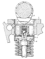
- valve train with a tappet is shown in longitudinal section:
- the tappet 3 which contains a hydraulic valve clearance compensation element in a known manner, is mounted so as to be longitudinally displaceable.
- the control cam 5 runs on the flat bottom 4 of the tappet 3, while the tappet, on the other hand, bears against the shaft 6 of a control valve.
- the bottom 4 of the tappet 3 is provided with a thin chrome layer 7 according to the invention.
Abstract
Bei einem Bauteil im Ventilsteuertrieb einer Brennkraftmaschine, gegen dessen Oberfläche (4) ein Steuernocken (5) anläuft, insbesondere einem Tassenstößel (3), wird zur Verbesserung des Verschleißverhaltens und damit zur Erzielung einer langen Lebensdauer auf die Oberfläche (4), gegen die der Steuernocken (5) anläuft, eine Chromschicht (7) mit einer Schichtdicke von maximal 5 µm, vorzugsweise 2,5 µm aufgebracht.In the case of a component in the valve control drive of an internal combustion engine, against whose surface (4) a control cam (5) starts, in particular a tappet (3), the surface (4) against which the Control cam (5) starts, a chrome layer (7) with a layer thickness of at most 5 microns, preferably 2.5 microns applied.
Description
Die Erfindung betrifft ein Bauteil im Ventilsteuertrieb einer Brennkraftmaschine, gegen dessen Oberfläche ein Steuernocken anläuft, insbesondere einen Tassenstößel.The invention relates to a component in the valve timing drive of an internal combustion engine, against the surface of which a control cam runs, in particular a bucket tappet.
Bei derartigen bekannten Bauteilen, insbesondere auch bei den neuerdings häufig verwendeten Tassenstößeln, stellt man fest, daß an der Fläche, an welcher der Steuernocken anläuft, auch unter günstigen Schmierbedingungen starker Verschleiß auftritt. Man hat versucht, dagegen anzugehen, indem man dieser Oberfläche z. B. durch Phosphatieren oder Cadmieren günstigere Gleiteigenschaften gegeben hat. Dies hatte jedoch nur geringen, insbesondere zeitlich eingeschränkten Erfolg. Man versuchte auch den Verschleiß durch Hartverchromen der Oberfläche, gegen die der Steuernocken anläuft, zu verringern, denn es war bekannt, daß Hartchromschichten sehr günstige Verschleißeigenschaften besitzen. Man hat dazu die für Hartchrom bewährten Schichtdicken von 10 µm und mehr aufgetragen. Die einschlägige Literatur nennt für Hartchromschichten Schichtdicken von 10 µm bis zu mehreren mm ("Galvanisierte Produkte" Gütesicherung RAL-RG 660, Teil 1 und Teil 2, Ausgabe November 1986, Deutsches Institut für Gütesicherung und Kennzeichnung). Diese sonst erfolgreiche Oberflächenbeschichtung brachte in der Praxis keinen Erfolg, weil die Chromschicht nach relativ kurzer Betriebsdauer abplatzte und damit den Verschleiß zusätzlich beschleunigte. Das Abplatzen der Chromschicht ist darauf zurückzuführen, daß die Oberfläche, auf die sie aufgebracht wurde, insbesondere der Boden von Tassenstößeln im Betrieb Durchbiegungen einer Größenordnung erleidet, welche eine bekannte Hartchromschicht nicht un beschädigt mitmachen kann. Es kommt deshalb zu Rissen und Abplatzungen.With known components of this type, in particular also with the cup tappets that have recently been used frequently, it is found that severe wear occurs on the surface on which the control cam runs, even under favorable lubrication conditions. Attempts have been made to tackle this by using this surface e.g. B. has given more favorable sliding properties by phosphating or cadmium coating. However, this had little, especially limited, success. Attempts have also been made to reduce the wear by hard chrome plating of the surface against which the control cam runs, since it was known that hard chrome plating had very favorable wear properties. The layer thicknesses of 10 µm and more, which have been tried and tested for hard chrome, have been applied. The relevant literature lists layer thicknesses of 10 µm up to several mm for hard chrome layers ("Galvanized products" quality assurance RAL-RG 660, part 1 and
Der Erfindung liegt die Aufgabe zugrunde, für derartige Bauteile eine Oberflächenbeschichtung vorzuschlagen, die neben günstigem Verschleißverhalten auch hohe Biegedauerfestigkeit, Druckfestigkeit und damit lange Lebensdauer des Bauteiles gewährleistet.The invention is based on the object of proposing a surface coating for components of this type which, in addition to favorable wear behavior, also ensures high flexural fatigue strength, compressive strength and thus long service life of the component.
Nach der Erfindung wird dieses Ziel dadurch erreicht, daß auf die Oberfläche des Bauteiles, gegen die der Steuernocken anläuft, eine Chromschicht mit einer Schichtdicke von maximal 5 µm, vorzugsweise 2,5 µm aufgebracht ist. Die Praxis hat gezeigt, daß eine derart dünne Schicht in der Lage ist, die an dem Bauteil, insbesondere am Boden eines Tassenstößels, auftretenden Verformungen und Drücke an den Stellen der Krafteinleitung zu ertragen, ohne daß schädliche Einflüsse auf die Lebensdauer der Chromschicht wirksam werden. Es wurden vielmehr im Versuch Standzeiten festgestellt, die weitaus höher lagen, als bei herkömmlichen Tassenstößeln ohne Oberflächenbehandlung.According to the invention, this aim is achieved in that a chrome layer with a layer thickness of at most 5 μm, preferably 2.5 μm, is applied to the surface of the component against which the control cam runs. Practice has shown that such a thin layer is able to withstand the deformations and pressures that occur on the component, in particular on the bottom of a cup tappet, at the points where force is applied, without having any detrimental effects on the life of the chrome layer. Rather, the service life was determined in the test, which was far higher than that of conventional tappets without surface treatment.
Als besonders zweckmäßig hat es sich erwiesen, wenn die Chromschicht aus mehreren nacheinander aufgebrachten Lagen besteht, von denen wenigstens die letzte, die die Gleitfläche für den Steuernocken bildet, Mikrorisse aufweist. Es hat sich gezeigt, daß es für die Gleiteigenschaften an der Oberfläche der Chromschicht von großer Bedeutung ist, daß dort Mikrorisse vorhanden sind, in denen sich Schmierstoff ansammeln kann. Für die Haltbarkeit der Chromschicht ist es andrerseits von wesentlicher Bedeutung, daß die erste, die Verbindung zu dem Werkstoff des Bauteiles herstellende Lage mikrorißfrei ist, um so Mikrokerbwirkung und damit Ansatzpunkte für ein eventuelles Abplatzen der Schicht zu vermeiden.It has proven to be particularly expedient if the chrome layer consists of a plurality of layers applied one after the other, at least the last of which, which forms the sliding surface for the control cam, has microcracks. It has been shown that it is of great importance for the sliding properties on the surface of the chrome layer that there are microcracks in which lubricant can accumulate. On the other hand, for the durability of the chrome layer, it is essential that the first layer, which creates the connection to the material of the component, is free of microcracks, in order to avoid micro-notching and thus starting points for a possible peeling of the layer.
Als besonders zweckmäßig hat es sich gezeigt, wenn die zuletzt aufgebrachte Lage wenigstens 600 Risse/cm aufweist.It has proven particularly expedient if the last layer applied has at least 600 cracks / cm.
Zweckmäßigerweise läßt sich die mikrorißfreie erste Lage durch elektrolytische Metallabscheidung (galvanisch) mit einer Stromdichte von ungefähr 15 A/dm² aufbringen, während die äußere, wenigstens 600 Risse/cm aufweisende Lage galvanisch mit einer Stromdichte von weniger als 15 A/dm² aufgebracht werden kann.The micro-crack-free first layer can expediently be applied by electrolytic metal deposition (electroplating) with a current density of approximately 15 A /
Um die Gefahr einer durch Wasserstoff verursachten Schädigung des Grundwerkstoffs zu vermindern, wird das mit Chrom fertig beschichtete Bauteil nach dem Galvanisieren zweckmäßigerweise erwärmt und vier Stunden lang auf einer Temperatur von ungefähr 120°C gehalten, bevor man es an der Luft abkühlen läßt.In order to reduce the risk of damage to the base material caused by hydrogen, the chromium-coated component is expediently heated after the electroplating and kept at a temperature of approximately 120 ° C. for four hours before being allowed to cool in air.
In der Zeichnung ist ein Ventiltrieb mit einem Tassenstößel im Längsschnitt dargestellt:In the drawing, a valve train with a tappet is shown in longitudinal section:
In einer Bohrung 1 des Zylinderkopfes 2 ist der Tassenstößel 3, der in bekannter Weise ein hydraulisches Ventilspielausgleichselement enthält, längsverschieblich gelagert. Auf dem ebenen Boden 4 des Tassenstößels 3 läuft der Steuernocken 5 an, während der Tassenstößel andererseits gegen den Schaft 6 eines Steuerventiles anliegt. Der Boden 4 des Tassenstößels 3 ist erfindungsgemäß mit einer dünnen Chromschicht 7 versehen.In a bore 1 of the
Claims (4)
Applications Claiming Priority (2)
| Application Number | Priority Date | Filing Date | Title |
|---|---|---|---|
| DE3809702 | 1988-03-23 | ||
| DE3809702A DE3809702A1 (en) | 1988-03-23 | 1988-03-23 | COMPONENT IN THE VALVE CONTROL DRIVE OF AN INTERNAL COMBUSTION ENGINE |
Publications (2)
| Publication Number | Publication Date |
|---|---|
| EP0334064A1 true EP0334064A1 (en) | 1989-09-27 |
| EP0334064B1 EP0334064B1 (en) | 1991-12-27 |
Family
ID=6350429
Family Applications (1)
| Application Number | Title | Priority Date | Filing Date |
|---|---|---|---|
| EP89103613A Expired - Lifetime EP0334064B1 (en) | 1988-03-23 | 1989-03-02 | Element in the valve gear of an internalcombustion engine |
Country Status (3)
| Country | Link |
|---|---|
| US (1) | US4876996A (en) |
| EP (1) | EP0334064B1 (en) |
| DE (2) | DE3809702A1 (en) |
Cited By (4)
| Publication number | Priority date | Publication date | Assignee | Title |
|---|---|---|---|---|
| EP0396288B1 (en) * | 1989-04-20 | 1993-06-16 | Eaton Engine Lifters Spa | Hydraulic tappet |
| US5267538A (en) * | 1991-06-07 | 1993-12-07 | Ina Walzlager Schaeffler Kg | Mechanical valve tappet for an internal combustion engine |
| DE4498820D2 (en) * | 1993-11-12 | 1997-07-24 | Schaeffler Waelzlager Kg | Tappet for a valve train of an internal combustion engine |
| WO2005121383A1 (en) | 2004-06-09 | 2005-12-22 | Schaeffler Kg | Heavy-duty engine component |
Families Citing this family (14)
| Publication number | Priority date | Publication date | Assignee | Title |
|---|---|---|---|---|
| DE4117425C1 (en) * | 1991-05-28 | 1992-07-30 | Fa. Carl Freudenberg, 6940 Weinheim, De | |
| DE4220584C2 (en) * | 1992-06-24 | 2001-02-01 | Schaeffler Waelzlager Ohg | Valve train of an internal combustion engine |
| US5226389A (en) * | 1992-11-04 | 1993-07-13 | Eaton Corporation | Direct acting tappet |
| US5249554A (en) * | 1993-01-08 | 1993-10-05 | Ford Motor Company | Powertrain component with adherent film having a graded composition |
| US5237967A (en) * | 1993-01-08 | 1993-08-24 | Ford Motor Company | Powertrain component with amorphous hydrogenated carbon film |
| DE4302877C2 (en) * | 1993-02-02 | 1996-04-11 | Schaeffler Waelzlager Kg | Pestle |
| EP0618351B1 (en) * | 1993-03-25 | 1997-08-06 | Fuji Oozx Inc. | Tappets for use in internal combustion engines |
| US5743224A (en) * | 1993-09-14 | 1998-04-28 | Unisia Jecs Corporation | Valve lifter surface and processing method thereof |
| US6119644A (en) * | 1997-05-22 | 2000-09-19 | Ina Walzlager Schaeffler Ohg | Hydraulic clearance compensation element |
| IT1302651B1 (en) * | 1998-10-13 | 2000-09-29 | Eaton Automotive Spa | HYDRAULIC TAPPETS WITH CONTROLLED HEIGHT LOSS. |
| KR100444566B1 (en) * | 1999-12-27 | 2004-08-16 | 닛폰 피스톤 린구 가부시키가이샤 | Sliding member |
| JP4059621B2 (en) * | 2000-09-29 | 2008-03-12 | 日本ピストンリング株式会社 | Chromium plating sliding member and manufacturing method thereof |
| US20050084610A1 (en) * | 2002-08-13 | 2005-04-21 | Selitser Simon I. | Atmospheric pressure molecular layer CVD |
| DE10249761A1 (en) * | 2002-10-25 | 2004-05-13 | Ina-Schaeffler Kg | Cam follower of a valve train of an internal combustion engine |
Citations (1)
| Publication number | Priority date | Publication date | Assignee | Title |
|---|---|---|---|---|
| GB1044692A (en) * | 1964-02-18 | 1966-10-05 | Daimler Benz Ag | Improvements relating to cam devices |
Family Cites Families (8)
| Publication number | Priority date | Publication date | Assignee | Title |
|---|---|---|---|---|
| US32167A (en) * | 1861-04-23 | Thomas h | ||
| US3131470A (en) * | 1960-12-09 | 1964-05-05 | Burgess Norton Mfg Co | Method of making valve lifters |
| DE1425653A1 (en) * | 1963-07-08 | 1969-01-23 | Richard Kuechen Sen | Valve drive with hydraulic backlash compensation |
| US3545415A (en) * | 1967-04-08 | 1970-12-08 | Nippon Piston Ring Co Ltd | Valve lifter with thin plastic coating |
| US4230491A (en) * | 1979-01-08 | 1980-10-28 | Stanadyne, Inc. | Internal combustion engine tappet comprising a sintered powdered metal wear resistant composition |
| US4367701A (en) * | 1979-12-05 | 1983-01-11 | Eaton Corporation | Acting valve gear |
| US4688526A (en) * | 1983-12-07 | 1987-08-25 | Eaton Corporation | Self-contained hydraulic bucket lifter |
| JPS62255507A (en) * | 1986-04-30 | 1987-11-07 | Hitachi Ltd | Manufacture of valve lifter |
-
1988
- 1988-03-23 DE DE3809702A patent/DE3809702A1/en not_active Withdrawn
-
1989
- 1989-03-02 EP EP89103613A patent/EP0334064B1/en not_active Expired - Lifetime
- 1989-03-02 DE DE8989103613T patent/DE58900604D1/en not_active Expired - Lifetime
- 1989-03-07 US US07/319,957 patent/US4876996A/en not_active Expired - Fee Related
Patent Citations (1)
| Publication number | Priority date | Publication date | Assignee | Title |
|---|---|---|---|---|
| GB1044692A (en) * | 1964-02-18 | 1966-10-05 | Daimler Benz Ag | Improvements relating to cam devices |
Non-Patent Citations (3)
| Title |
|---|
| AUTOMOTIVE ENGINEERING, Band 94, Mai 1986, Seiten 40-45, Society of automotive Engineers, Inc., Dallas, Texas, US; "Valve gear materials: An overview" * |
| PATENT ABSTRACTS OF JAPAN, Band 11, Nr. 330 (M-636)[2777], 28. Oktober 1987; & JP-A-62 111 106 (HITACHI LTD) 22-05-1987 * |
| PATENT ABSTRACTS OF JAPAN, Band 9, Nr. 103 (M-377)[1826], 8. Mai 1985, Seite 153 M 377; & JP-A-59 229 009 (TOYOTA JIDOSHA K.K.) 22-12-1984 * |
Cited By (4)
| Publication number | Priority date | Publication date | Assignee | Title |
|---|---|---|---|---|
| EP0396288B1 (en) * | 1989-04-20 | 1993-06-16 | Eaton Engine Lifters Spa | Hydraulic tappet |
| US5267538A (en) * | 1991-06-07 | 1993-12-07 | Ina Walzlager Schaeffler Kg | Mechanical valve tappet for an internal combustion engine |
| DE4498820D2 (en) * | 1993-11-12 | 1997-07-24 | Schaeffler Waelzlager Kg | Tappet for a valve train of an internal combustion engine |
| WO2005121383A1 (en) | 2004-06-09 | 2005-12-22 | Schaeffler Kg | Heavy-duty engine component |
Also Published As
| Publication number | Publication date |
|---|---|
| DE3809702A1 (en) | 1989-10-05 |
| DE58900604D1 (en) | 1992-02-06 |
| US4876996A (en) | 1989-10-31 |
| EP0334064B1 (en) | 1991-12-27 |
Similar Documents
| Publication | Publication Date | Title |
|---|---|---|
| EP0334064B1 (en) | Element in the valve gear of an internalcombustion engine | |
| DE19944977B4 (en) | Coatings for use in fuel injector components | |
| EP1781835B1 (en) | Wear-resistant coating and method for producing the same | |
| DE102006029415B4 (en) | Wear-resistant coating and manufacturing process therefor | |
| DE102009028504C5 (en) | Piston ring with a coating | |
| EP1634978A1 (en) | Wear resistant coating and process of its manufacture | |
| DE102004041234A1 (en) | Wear resistant coating and method of making same | |
| WO1997016578A1 (en) | Method of producing a slide surface on a metal workpiece | |
| EP2209927A2 (en) | Corrosion-resistant coating and method for producing same | |
| DE102012203432A1 (en) | Engine without cylinder liner | |
| DE19824310C1 (en) | Bearing surface for metal bearing | |
| DE4019644A1 (en) | VALVE STOOL STRUCTURE | |
| DE2926708A1 (en) | METHOD FOR PRODUCING WORKPIECES WITH ADAPTING LAYER FOR USE WITH EXTREMELY HIGH AREA PRESSURE AND WORKPIECES WITH SUCH ADAPTING LAYER | |
| EP1637623A1 (en) | Spray powder, bearing element of a bearing device coated with the sprayed powder | |
| DE19540572C2 (en) | Process for producing a sliding surface on a metal workpiece that ensures hydrodynamic lubrication during operation, and a reciprocating piston machine with cylinder liners produced thereafter | |
| DE2921952A1 (en) | Light alloy piston for IC engine - has hard wearing surface layer of aluminium oxide deposited electrolytically | |
| EP3414356A1 (en) | Tribological system of an internal combustion engine with a coating | |
| DE3301366A1 (en) | Piston for internal combustion engines | |
| DE10339711A1 (en) | Piston with piston ring | |
| DE19704224A1 (en) | Connection between lifting piston and connecting rod in vehicle engines | |
| DE102005037206A1 (en) | Assembly for an internal combustion engine | |
| DE19852265A1 (en) | Engine cam tappet roller pin | |
| DE3623360A1 (en) | Device with adjacent surfaces, between which high pressures and/or high friction loads occur | |
| EP1045175B1 (en) | Packing ring | |
| DE3917951A1 (en) | Nitrided piston ring |
Legal Events
| Date | Code | Title | Description |
|---|---|---|---|
| PUAI | Public reference made under article 153(3) epc to a published international application that has entered the european phase |
Free format text: ORIGINAL CODE: 0009012 |
|
| 17P | Request for examination filed |
Effective date: 19890302 |
|
| AK | Designated contracting states |
Kind code of ref document: A1 Designated state(s): DE FR GB |
|
| 17Q | First examination report despatched |
Effective date: 19901123 |
|
| GRAA | (expected) grant |
Free format text: ORIGINAL CODE: 0009210 |
|
| AK | Designated contracting states |
Kind code of ref document: B1 Designated state(s): DE FR GB |
|
| PGFP | Annual fee paid to national office [announced via postgrant information from national office to epo] |
Ref country code: FR Payment date: 19920124 Year of fee payment: 4 |
|
| REF | Corresponds to: |
Ref document number: 58900604 Country of ref document: DE Date of ref document: 19920206 |
|
| ET | Fr: translation filed | ||
| GBT | Gb: translation of ep patent filed (gb section 77(6)(a)/1977) | ||
| PLBE | No opposition filed within time limit |
Free format text: ORIGINAL CODE: 0009261 |
|
| STAA | Information on the status of an ep patent application or granted ep patent |
Free format text: STATUS: NO OPPOSITION FILED WITHIN TIME LIMIT |
|
| 26N | No opposition filed | ||
| PG25 | Lapsed in a contracting state [announced via postgrant information from national office to epo] |
Ref country code: GB Effective date: 19930302 |
|
| GBPC | Gb: european patent ceased through non-payment of renewal fee |
Effective date: 19930302 |
|
| PG25 | Lapsed in a contracting state [announced via postgrant information from national office to epo] |
Ref country code: FR Effective date: 19931130 |
|
| REG | Reference to a national code |
Ref country code: FR Ref legal event code: ST |
|
| PGFP | Annual fee paid to national office [announced via postgrant information from national office to epo] |
Ref country code: DE Payment date: 20010316 Year of fee payment: 13 |
|
| PG25 | Lapsed in a contracting state [announced via postgrant information from national office to epo] |
Ref country code: DE Free format text: LAPSE BECAUSE OF NON-PAYMENT OF DUE FEES Effective date: 20021001 |