EP0333629B1 - Verbundkörper mit Metallmatrix und Verfahren zu ihrer Herstellung - Google Patents
Verbundkörper mit Metallmatrix und Verfahren zu ihrer Herstellung Download PDFInfo
- Publication number
- EP0333629B1 EP0333629B1 EP89630051A EP89630051A EP0333629B1 EP 0333629 B1 EP0333629 B1 EP 0333629B1 EP 89630051 A EP89630051 A EP 89630051A EP 89630051 A EP89630051 A EP 89630051A EP 0333629 B1 EP0333629 B1 EP 0333629B1
- Authority
- EP
- European Patent Office
- Prior art keywords
- metal
- matrix
- matrix composite
- molten
- filler material
- Prior art date
- Legal status (The legal status is an assumption and is not a legal conclusion. Google has not performed a legal analysis and makes no representation as to the accuracy of the status listed.)
- Expired - Lifetime
Links
Images
Classifications
-
- C—CHEMISTRY; METALLURGY
- C22—METALLURGY; FERROUS OR NON-FERROUS ALLOYS; TREATMENT OF ALLOYS OR NON-FERROUS METALS
- C22C—ALLOYS
- C22C1/00—Making non-ferrous alloys
- C22C1/10—Alloys containing non-metals
- C22C1/1036—Alloys containing non-metals starting from a melt
Definitions
- the present invention relates to novel ceramic-filled metal matrix composites and methods for making the same.
- a permeable mass of ceramic filler is spontaneously infiltrated (i.e., without the application of any applied pressure or vacuum) by a molten metal alloy, such as an aluminum alloy, in the presence of a nitrogen-containing atmosphere.
- metal matrix composite bodies can be produced by using a reservoir feed method.
- the metal is initially present as a first source and as a reservoir, the first source and reservoir communicating with each other such that a sufficient amount of metal is present to permeate completely the ceramic filler.
- the reservoir can contain an excess amount of metal (i.e., more metal can be present than that amount which is needed for complete infiltration) and such excess metal can be bonded directly to the ceramic-filled metal matrix composite, thus forming a novel complex composite body comprising a metal bonded to a metal matrix composite body.
- a metal matrix composite is produced by infiltrating a permeable mass of ceramic filler or ceramic-coated filler with molten aluminum containing at least about 1% of weight magnesium, and preferably at least about 3% by weight magnesium. Infiltration occurs spontaneously without the application of external pressure or vacuum.
- a supply of the molten metal alloy is contacted with the mass of filler material at a temperature of at least about 675°C in the presence of a gas comprising from about 10 to 100%, and preferably at least about 50%, nitrogen by volume, and a remainder of the gas being a nonoxidizing gas, e.g., argon.
- a gas comprising from about 10 to 100%, and preferably at least about 50%, nitrogen by volume, and a remainder of the gas being a nonoxidizing gas, e.g., argon.
- the molten aluminum alloy infiltrates the ceramic mass under normal atmospheric pressures to form an aluminum matrix composite.
- the temperature is lowered to solidify the alloy, thereby forming a solid metal matrix structure that embeds the reinforcing ceramic material.
- the supply of molten alloy delivered will be sufficient to permit the infiltration to proceed essentially to the boundaries of the ceramic mass.
- the amount of ceramic filler in the aluminum matrix composites produced according to the White et al. invention may be exceedingly high. In this respect, filler to alloy volumetric ratios of greater than 1:1 may be achieved.
- aluminum nitride can form as a discontinuous phase dispersed throughout the aluminum matrix.
- the amount of nitride in the aluminum matrix may vary depending on such factors as temperature, alloy compositions, gas composition, and ceramic filler. Thus, by controlling one or more such factors in the system, it is possible to tailor certain properties of the composite. For some end use applications, however, it is desirable that the composite contain little or substantially no aluminum nitride.
- the White et al. invention achieves a good balance between infiltration kinetics and minimal nitride formation.
- the composite body which is produced comprises a self-supporting ceramic composite structure which includes a ceramic matrix obtained by the oxidation reaction of a parent metal with on oxidant to form a polycrystalline material.
- a body of the parent metal and a permeable filler are oriented relative to each other so that formation of the oxidation reaction product will occur in a direction toward and into the filler.
- the parent metal is described as being present as a first source and as a reservoir, the reservoir of metal communicating with the first source due to, for example, gravity flow.
- the first source of molten parent metal reacts with the oxidant to begin the formation of the oxidation reaction product.
- the first source of molten parent metal As the first source of molten parent metal is consumed, it is replenished, preferably by a continuous means, from the reservoir of parent metal as the oxidation reaction product continues to be produced and infiltrates the filler.
- the reservoir assures that ample parent metal will be available to continue the process until the oxidation reaction product has grown to a desired extent.
- the resulting composite product can be a metal matrix composite surface on a metal substrate.
- the metal matrix embeds a filler at a surface of the first source of metal, and the resulting metal matrix composite may be formed either as an exterior or an interior surface, or both, on the substrate of the metal.
- the metal matrix composite surface can have a selected or predetermined thickness with respect to the metal substrate.
- Composite products comprising a metal matrix and a strengthening or reinforcing phase such as ceramic particulates, whiskers, fibers or the like, show great promise for a variety of applications because they combine some of the stiffness and wear resistance of the reinforcing phase with the ductility and toughness of the metal matrix.
- a metal matrix composite will show an improvement in such properties as strength, stiffness, contact wear resistance, and elevated temperature strength retention relative the matrix metal in monolithic form, but the degree to which any given property may be improved depends largely on the specific constituents, their volume or weight fraction, and how they are processed in forming the composite. In some instances, the composite also may be lighter in weight than the matrix metal per se.
- Aluminum matrix composites reinforced with ceramics such as silicon carbide in particulate, platelet, or whisker form, for example, are of interest because of their higher stiffness, wear resistance and high temperature strength relative to aluminum.
- U.S. Patent No. 3,970,136 granted July 20, 1976, to J. C. Cannell et al., describes a process for forming a metal matrix composite incorporating a fibrous reinforcement, e.g. silicon carbide or alumina whiskers, having a predetermined pattern of fiber orientation.
- the composite is made by placing parallel mats or felts of coplanar fibers in a mold with a reservoir of molten matrix metal, e.g., aluminum, between at least some of the mats, and applying pressure to force molten metal to penetrate the mats and surround the oriented fibers.
- Molten metal may be poured onto the stack of mats while being forced under pressure to flow between the mats. Loadings of up to about 50% by volume of reinforcing fibers in the composite have been reported.
- the above-described infiltration process in view of its dependence on outside pressure to force the molten matrix metal through the stack of fibrous mats, is subject to the vagaries of pressure-induced flow processes, i.e., possible non-uniformity of matrix formation, porosity, etc.
- Non-uniformity of properties is possible even though molten metal may be introduced at a multiplicity of sites within the fibrous array. Consequently, complicated mat/ reservoir arrays and flow pathways need to be provided to achieve adequate and uniform penetration of the stack of fiber mats.
- the aforesaid pressure-infiltration method allows for only a relatively low reinforcement to matrix volume fraction to be achieved because of difficulty of infiltrating a large mat volume.
- aluminum does not readily wet alumina, thereby making it difficult to form a coherent product.
- Various solutions to this problem have been suggested.
- One such approach is to coat the alumina with a metal (e.g., nickel or tungsten), which is then hot-pressed along with the aluminum.
- the aluminum is alloyed with lithium, and the alumina may be coated with silica.
- these composites exhibit variations in properties, or the coatings can degrade the filler, or the matrix contains lithium which can affect the matrix properties.
- U.S. Patent No. 4,232,091 to R. W. Grimshaw et al. overcomes certain difficulties in the art which are encountered in the production of aluminum matrix-alumina composites.
- This patent describes applying pressures of 7,4-36,8 MPa (75-375 kg/cm2)to force molten aluminum (or molten aluminum alloy) into a fibrous or whisker mat of alumina which has been preheated to 700 to 1050°C.
- the maximum volume ratio of alumina to metal in the resulting solid casting was 0.25/1. Because of its dependency on outside force to accomplish infiltration, this process is subject to many of the same deficiencies as that of Cannell et al.
- EP-A-115,742 describes making aluminum-alumina composites, especially useful as electrolytic cell components, by filling the voids of a preformed alumina matrix with molten aluminum.
- the application emphasizes the non-wettability of alumina by aluminum, and therefore various techniques are employed to wet the alumina throughout the preform.
- the alumina is coated with a wetting agent of a diboride of titanium, zirconium, hafnium, or niobium, or with a metal, i.e., lithium, magnesium, calcium, titanium, chromium, iron, cobalt, nickel, zirconium, or hafnium.
- Inert atmospheres, such as argon are employed to facilitate wetting.
- This reference also shows applying pressure to cause molten aluminum to penetrate an uncoated matrix.
- infiltration is accomplished by evacuating the pores and then applying pressure to the molten aluminum in an inert atmosphere, e.g., argon.
- the preform can be infiltrated by vapor-phase aluminum deposition to wet the surface prior to filling the voids by infiltration with molten aluminum.
- heat treatment e.g., at 1400 to 1800°C, in either a vacuum or in argon is required. Otherwise, either exposure of the pressure infiltrated material to gas or removal of the infiltration pressure will cause loss of aluminum from the body.
- wetting agents to effect infiltration of an alumina component in an electrolytic cell with molten metal is also shown in EP-A-94353.
- This publication describes production of aluminum by electrowinning with a cell having a cathodic current feeder as a cell liner or substrate.
- a thin coating of a mixture of a wetting agent and solubility suppressor is applied to the alumina substrate prior to start-up of the cell or while immersed in the molten aluminum produced by the electrolytic process.
- Wetting agents disclosed are titanium, zirconium, hafnium, silicon, magnesium, vanadium, chromium, niobium, or calcium, and titanium is stated as the preferred agent.
- a vacuum of 1.3 to 1.3 x 10 ⁇ 4 Pa (10 ⁇ 2 to 10 ⁇ 6 torr) resulted in poor wetting of the ceramic by the molten metal to the extent that the metal did not flow freely into the ceramic void spaces.
- wetting was said to have improved when the vacuum was reduced to less than 1.3 x 10 ⁇ 4 Pa (10 ⁇ 6 torr).
- U.S. Patent No. 3,364,976, granted January 23, 1968 to John N. Reding et al. discloses the concept of creating a self-generated vacuum in a body to enhance penetration of a molten metal into the body. Specifically, it is disclosed that a body, e.g., a graphite mold, a steel mold, or a porous refractory material, is entirely submerged in a molten metal . In the case of a mold, the mold cavity, which is filled with a gas reactive with the metal, communicates with the externally located molten metal through at least one orifice in the mold.
- a body e.g., a graphite mold, a steel mold, or a porous refractory material
- Molds must first be machined into a particular shape; then finished, machined to produce an acceptable casting surface on the mold; then assembled prior to their use; then disassembled after their use to remove the cast piece therefrom; and thereafter reclaim the mold, which most likely would include refinishing surfaces of mold. Machining of a mold into a complex shape can be very costly and time-consuming. Moreover, removal of a formed piece from a complex-shaped mold can also be difficult (i.e., cast pieces having a complex shape could be broken when removed from the mold).
- a porous refractory material can be immersed directly in a molten metal without the need for a mold
- the refractory material would have to be an integral piece because there is no provision for infiltrating a loose or separated porous material absent the use of a container mold (i.e., the particulate material would typically disassociate or float apart when placed in a molten metal).
- the infiltrating metal would probably displace at least portions of the particulate or preform resulting in a non-homogeneous microstructure.
- the present invention satisfies this need by providing a spontaneous infiltration mechanism for infiltrating a ceramic material with molten aluminum alloys under atmospheric pressure so long as certain processing criteria are satisfied.
- the present invention also provides a simple and economical solution to the persistent problem of bonding a metal to a metal matrix composite body, thus forming a complex composite body.
- the present method can be utilized to produce a metal matrix composite by infiltrating a permeable mass of ceramic filler or ceramic-coated filler with molten aluminum containing at least about 1% by weight magnesium, and preferably at least about 3% by weight magnesium. Infiltration occurs spontaneously (i.e., without the need for the application of an external pressure or a high vacuum).
- a supply of the molten aluminum is contacted with the mass of filler material at a temperature of at least about 700°C in the presence of a gas comprising from about 10 to 100%, by volume, and preferably at least about 50% nitrogen, by volume, the balance being a nonoxidizing gas such as argon.
- the matrix metal alloy is present as a first source of metal and as a reservoir of matrix metal alloy which is communicating with the first source of molten metal due to, for example, gravity flow.
- the first source of molten aluminum alloy begins to infiltrate the ceramic mass under normal atmospheric pressures to begin the formation of an aluminum matrix composite.
- the first source of molten metal alloy is consumed during its infiltration into the ceramic mass and, if desired, can be replenished, preferably by a continuous means, from the reservoir of molten metal as the spontaneous infiltration continues.
- the reservoir of metal can be present in an amount such that it provides for a sufficient amount of metal to infiltrate the permeable ceramic mass to a predetermined extent.
- an optional barrier means can contact the permeable ceramic mass on at least one side thereof to define a surface boundary.
- the barrier means is used to inhibit, prevent or terminate infiltration of the molten alloy thereby providing net, or near net, shapes in the resultant metal matrix composite.
- the supply of molten alloy delivered should be at least sufficient to permit spontaneous infiltration to proceed essentially to the boundaries (i.e., barriers) of the permeable ceramic mass, the amount of alloy present in the reservoir could exceed such sufficient amount so that not only will there be a sufficient amount of alloy for complete infiltration, but excess molten metal alloy could remain.
- the resulting body will be a complex composite body, wherein an infiltrated ceramic body having an aluminum matrix therein will be directly bonded to excess matrix metal remaining in the reservoir.
- the present invention provides not only significant processing advantages in producing self-supporting metal matrix composite structures, but enables the production of novel complex composite bodies, namely, metal matrix composite surfaced metal structures, in which the metal matrix composite surface is formed from the metal infiltrated ceramic mass. That is, the matrix metal infiltrates the ceramic mass and because the infiltrated matrix is integral with the metal, the resulting composite product comprises a metal matrix composite surface on a metal substrate.
- the metal matrix composite surface includes a filler, and the metal matrix surface may be formed either as an exterior or an interior surface, or both, on a substrate of the metal, and the metal matrix composite surface may be of a selected or a predetermined thickness with respect to the metal substrate.
- the techniques of the present invention also enable the production of a series of metal matrix composite structures from a common source of matrix metal, thus considerably enhancing efficiency of operation.
- a metal matrix composite surfaced metal substrate part wherein said substrate is bonded to the metal matrix composite on the surface.
- a metal matrix composite surfaced metal substrate part wherein the metal matrix composite surface is in compression and the metal substrate is in tension at the interface between the two.
- an optional nitride skin can be grown on an outer surface of the infiltrated metal matrix.
- Such skin can be grown due to prolonged exposure of the molten metal alloy to the nitrogen atmosphere. It may be desirable to form such a skin to improve the wear resistance of the composite body.
- a first source of an aluminum-magnesium matrix metal alloy is positioned such that it is in communication with a surface of a permeable mass of ceramic material (e.g., ceramic particles, whiskers, or fibers) so that when the aluminum-magnesium alloy is in the molten stage, it can spontaneously infiltrate the permeable mass of ceramic material.
- a reservoir of matrix metal is in communication with the first source of matrix metal alloy so that the reservoir matrix metal flows to replenish, and in some cases to provide initially and subsequently replenish, that portion, segment or source of matrix metal which has infiltrated into the permeable mass of ceramic material, such infiltration occurring in the presence of a nitrogen-containing gas spontaneously and progressively.
- a barrier means such as titanium diboride or a graphite tape product by Union Carbide, and known by the name Grafoil®, may optionally be provided to define or coincide with at least one surface of the permeable mass of ceramic material, thereby defining an exterior surface of the composite body to be formed.
- the ceramic mass or body is sufficiently permeable to permit a nitrogen-containing gas to penetrate the body and contact the molten metal. Moreover, the permeable ceramic mass or body can accommodate infiltration of the molten metal, thereby causing the nitrogen-permeated ceramic mass to be infiltrated spontaneously with the molten metal alloy to form a metal matrix composite body.
- the extent of spontaneous infiltration and formation of the metal matrix will vary with a given set of process conditions, including magnesium content of the aluminum alloy, the presence of additional alloying elements (e.g., silicon, iron, copper, manganese, chromium, zinc, and the like), size of the filler material particles, surface condition and type of filler material, nitrogen concentration of the gas, time permitted for infiltration and temperature at which infiltration occurs.
- additional alloying elements e.g., silicon, iron, copper, manganese, chromium, zinc, and the like
- size of the filler material particles e.g., silicon, iron, copper, manganese, chromium, zinc, and the like
- size of the filler material particles e.g., silicon, iron, copper, manganese, chromium, zinc, and the like
- size of the filler material particles e.g., silicon, iron, copper, manganese, chromium, zinc, and the like
- size of the filler material particles e.g., silicon
- the auxiliary alloying elements may affect the minimum amount of magnesium that is necessary to result in spontaneous infiltration of the permeable mass.
- Volatilization of magnesium, etc. can be a problem.
- the volume percent of nitrogen in the nitrogen atmosphere also affects formation rates of the metal matrix composite body. Specifically, if less than about 10 volume percent of nitrogen is present in the atmosphere, very slow or little spontaneous infiltration will occur. It has been discovered that it is preferable for at least about 50 volume percent of nitrogen to be present in the atmosphere, thereby resulting in, for example, shorter infiltration times due to a much more rapid rate of infiltration.
- the matrix metal in the reservoir could be of a composition exactly the same as the first source of matrix metal or could be quite different in composition.
- the different metal could be utilized in this process.
- Such a different metal when present as residual metal in a complex composite body, could be used to modify physical and/or chemical properties of the first source of matrix metal to, for example, increase the melting point of the first source, increase the corrosion resistance of the first source, etc.
- the minimum magnesium content of the aluminum alloy useful in producing a ceramic filled metal matrix composite depends on one or more variables such as the processing temperature, time, the presence of auxiliary alloying elements such as silicon or zinc, the nature of the ceramic filler material, and the nitrogen content of the gas stream. Lower temperatures or shorter heating times can be used to obtain complete infiltration as the magnesium content of the alloy is increased. Also, for a given magnesium content, the addition of certain auxiliary alloying elements such as zinc permits the use of lower temperatures.
- a magnesium content at the lower end of the operable range e.g., from about 1 to 3 weight percent, may be used in conjunction with at least one of the following: an above-minimum processing temperature, a high nitrogen concentration, or one or more auxiliary alloying elements.
- Alloys containing from about 3 to 5 weight percent magnesium are preferred on the basis of their general utility over a wide variety of process conditions, with at least about 5% being preferred when lower temperatures and shorter times are employed.
- Magnesium contents in excess of about 10% by weight of the aluminum alloy may be employed to moderate the temperature conditions required for infiltration.
- the magnesium content may be reduced when used in conjunction with an auxiliary alloying element, but these elements serve an auxiliary function only and are used together with the above-specified amount of magnesium. For example, there was substantially no infiltration of nominally pure aluminum alloyed only with 10% silicon at 1000°C into a bedding of 25 ⁇ m (500 mesh), 39 Crystolon (99% pure silicon carbide from Norton Co.).
- the auxiliary alloying element(s) on a surface of the alloy prior to infiltrating the alloy into the permeable mass or into the permeable mass itself.
- the alloying element of magnesium could be externally applied as a dopant of, for example, Mg, Mg3N4, etc., on the surface of the first matrix metal source which is closest to, or preferably in contact with, the permeable mass of ceramic material; or such dopants could be mixed into at least a portion of the permeable mass of ceramic material.
- some combination of external doping and placement of dopants into at least a portion of the permeable mass of ceramic material could be used.
- auxiliary alloying elements and the concentration of nitrogen in the surrounding gas also affects the extent of nitriding of the alloy matrix at a given temperature. For example, increasing the concentration of an auxiliary alloying element such as zinc or iron in the alloy, or placed on a surface of the alloy, may be used to reduce the infiltration temperature and thereby decrease the nitride formation, whereas increasing the concentration of nitrogen in the gas may be used to promote nitride formation.
- the concentration of magnesium in the alloy, or doped onto a surface of the alloy also tends to affect the extent of infiltration at a given temperature. Consequently, it is preferred that at least about three weight percent magnesium be included in the alloy. Alloy contents of less than this amount, such as one weight percent magnesium, tend to require higher process temperatures or an auxiliary alloying element for infiltration.
- the temperature required to effect the spontaneous infiltration process of this invention may be lower: (1) when the magnesium content of the alloy is increased, e.g. to at least about 5 weight percent; (2) when dopants are mixed with the permeable mass of ceramic material; and/or (3) when another element such as zinc or iron is present in the aluminum alloy. The temperature also may vary with different ceramic materials.
- spontaneous and progressive infiltration will occur at a process temperature of at least about 675°C, and preferably a process temperature of at least about 800°C. Temperatures generally in excess of 1200°C do not appear to benefit the process, and a particularly useful temperature range has been found to be about from 675°C to 1200°C.
- molten aluminum alloy is delivered to a mass of permeable ceramic material in the presence of a nitrogen-containing gas maintained for the entire time required to achieve infiltration. This is accomplished by maintaining a continuous flow of gas into contact with the lay-up of ceramic material and molten aluminum alloy.
- a nitrogen-containing gas maintained for the entire time required to achieve infiltration.
- the flow rate of the nitrogen-containing as is not critical, it is preferred that the flow rate be sufficient to compensate for any nitrogen lost from the atmosphere due to nitride formation in the alloy matrix, and also to prevent or inhibit the incursion of air which can have an oxidizing effect on the molten metal.
- the method of this invention is applicable to a wide variety of ceramic materials, and the choice of filler material will depend on such factors as the aluminum alloy, the process conditions, the reactivity of the molten aluminum with the filler material, and the properties sought for the final composite product.
- These materials include (a) oxides, e.g. alumina, magnesia, titania, zirconia and hafnia; (b) carbides, e.g. silicon carbide and titanium carbide; (c) borides, e.g. titanium diboride, aluminum dodecaboride, and (d) nitrides, e.g. aluminum nitride, silicon nitride, and zirconium nitride.
- oxides e.g. alumina, magnesia, titania, zirconia and hafnia
- carbides e.g. silicon carbide and titanium carbide
- borides e.g. titanium diboride, aluminum dodecabor
- the filler material may comprise a substrate, such as carbon or other non-ceramic material, bearing a ceramic coating to protect the substrate from attack or degradation.
- Suitable ceramic coatings include the oxides, carbides, borides and nitrides. Ceramics which are preferred for use in the present method include alumina and silicon carbide in the form of particles, platelets, whiskers and fibers.
- the fibers can be discontinuous (in chopped form) or in the form of continuous filament, such as multifilament tows. Further, the ceramic mass or preform may be homogeneous or heterogeneous.
- Silicon carbide reacts with molten aluminum to form aluminum carbide, and if silicon carbide is used as the filler material, it is desirable to prevent or minimize this reaction.
- Aluminum carbide is susceptible to attack by moisture, which potentially weakens the composite. Consequently, to minimize or prevent this reaction, the silicon carbide is prefired in air to form a reactive silica coating thereon, or the aluminum alloy is further alloyed with silicon, or both. In either case, the effect is to increase the silicon content in the alloy to eliminate the aluminum carbide formation. Similar methods can be used to prevent undesirable reactions with other filler materials.
- the size and shape of the ceramic material can be any that may be required to achieve the properties desired in the composite.
- the material may be in the form of particles, whiskers, platelets or fibers since infiltration is not restricted by the shape of the filler material. Other shapes such as spheres, tubules, pellets, refractory fiber cloth, and the like may be employed.
- the size of the material does not limit infiltration, although a higher temperature or longer time period may be needed for complete infiltration of a mass of smaller particles than for larger particles.
- the mass of ceramic material to be infiltrated is permeable, i.e., permeable to molten aluminum alloys and to nitrogen-containing gases.
- the ceramic material can be either at its pour density or compressed to a greater density.
- the method of the present invention permits the production of substantially uniform aluminum alloy matrix composites having a high volume fraction of ceramic material and low porosity.
- Higher volume fractions of ceramic material may be achieved by using a lower porosity initial mass of ceramic material.
- Higher volume fractions also may be achieved if the ceramic mass is compacted under pressure provided that the mass is not converted into either a compact with closed cell porosity or into a fully dense structure that would prevent infiltration by the molten alloy.
- the specific process temperature at which nitride formation becomes more pronounced also varies with such factors as the aluminum alloy used and its quantity relative to the volume of filler, the ceramic material to be infiltrated, and the nitrogen concentration of the gas used.
- the extent of aluminum nitride formation at a given process temperature is believed to increase as the ability of the alloy to wet the ceramic filler decreases and as the nitrogen concentration of the gas increases.
- the process temperature can be selected to control the nitride formation.
- a composite product containing an aluminum nitride phase wilt exhibit certain properties which can be favorable to, or improve the performance of, the product.
- the temperature range for spontaneous infiltration with aluminum alloy may vary with the ceramic material used. In the case of alumina as the filler material, the temperature for infiltration should preferably not exceed about 1000°C in order to insure that the ductility of the matrix is not reduced by the significant formation of any nitride. However, temperatures exceeding 1000°C may be employed if it is desired to produce a composite with a less ductile and stiffer matrix.
- a matrix metal in the reservoir which differs in composition from the first source of matrix metal.
- a matrix metal in the reservoir which differs in composition from the first source of matrix metal.
- an aluminum alloy is used as the first source of matrix metal
- virtually any other metal or metal alloy which was molten at the processing temperature could be used as the reservoir metal. Molten metals frequently are very miscible with each other which would result in the reservoir metal mixing with the first source of matrix metal so long as an adequate amount of time is given for the mixing to occur.
- a reservoir metal which is different in composition than the first source of matrix metal it is possible to tailor the properties of the metal matrix to meet various operating requirements and thus tailor the properties of the metal matrix composite.
- the composite is provided with an aluminum nitride skin or surface.
- the amount of the alloy is sufficient to infiltrate essentially the entire bed of ceramic material, that is, to the defined boundaries.
- an aluminum nitride layer or zone may form on or along the outer surface of the composite due to nitriding of the surface regions of the infiltrating front of aluminum alloy. That portion of the bed not embedded by the matrix is readily removed, if desired, as by grit blasting.
- a nitride skin can be formed at the surface of the bed or preform infiltrated to its boundary by prolonging the process conditions.
- an open vessel which is nonwettable by the molten aluminum alloy is filled with the permeable ceramic filler, and the top surface of the ceramic bed is exposed to the nitrogen gas.
- the molten aluminum at the exposed surface will nitride.
- the degree of nitridation can be controlled, and may be formed as either a continuous phase or a discontinuous phase in the skin layer. It therefore is possible to tailor the composite for specific applications by controlling of the extent of nitride formation on the surface of the composite. For example, aluminum matrix composites bearing a surface layer of aluminum nitride may be produced exhibiting improved wear resistance relative to the metal matrix.
- molten aluminum-magnesium alloys spontaneously infiltrate a permeable mass of ceramic material due to their tendency to wet a ceramic material permeated with nitrogen gas.
- Auxiliary alloying elements such as silicon and zinc may be included in the aluminum alloys to permit the use of lower temperatures and lower magnesium concentrations.
- Aluminum-magnesium alloys which include 10-20% or more of silicon therein are preferred for infiltrating unfired silicon carbide since silicon tends to minimize reaction of the molten alloy with silicon carbide to form aluminum carbide.
- the aluminum alloys employed in the invention may include various other alloying elements to provide specifically desired mechanical and physical properties in the alloy matrix.
- copper additives may be included in the alloy to provide a matrix which may be heat treated to increase hardness and strength.
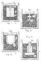
- the numeral 1 represents a refractory container
- the numeral 2 represents an inert bedding or barrier material of Grade HTC titanium diboride
- the numeral 3 represents a first source of matrix metal
- the numeral 4 represents a reservoir of matrix metal
- the numeral 5 represents a permeable mass of ceramic material (e.g., a ceramic preform) into which a molten metal spontaneously infiltrates.
- Figure 1 shows a typical setup wherein a permeable mass of ceramic material 5 (in this case shaped into a preform) is in contact with a first source of matrix metal 3. It is clear from Figure 1, even though not drawn exactly to scale, that the amount of matrix metal contained in the first source of matrix metal is not sufficient to infiltrate completely the preform 5. Thus, a reservoir source of matrix metal 4, is in contact with the first souce of matrix metal 3 thus providing communication therebetween. Particularly, at infiltration temperatures, the first source of matrix metal is plenished by the reservoir of matrix metal 4 to permit complete infiltration of the preform 5. Moreover, it is possible to feed excess matrix metal from the reservoir to result in a complex composite body. Particularly, as discussed above herein, the complex composite body comprises a matrix metal substrate surrounded by a metal matrix composite.
- Figure 2 shows generally a reservoir feed metal matrix composite embodiment wherein an aluminum alloy 3,4 spontaneously infiltrates a ceramic preform 5.
- the composition of the aluminum alloy was about 83% aluminum, 5% silicon, 5% zinc, and 7% magnesium, by weight.
- the ceramic preform was prepared by slipcasting a camshaft.
- the composition of the slip was about 70% A-17 Al2O3 and about 30 weight percent EPK (Edgars Plastic Kaolin).
- the slipcast part was prepared by combining powder components with a predetermined quantity of water containing Veegum CER.
- the Kaolin clay was added to the water first, followed by alumina powder.
- the slurry was mixed at a high sheer rate for about one hour and then rolled in a jar on a pair of rollers overnite (e.g., about 10 hours) to age it. Casting was conducted in Plaster of Paris molds which were shaped appropriately. After the preforms were cast and released, they were dried for about two hours in an oven at about 90°C. It was then necessary to prefire these pieces at a temperature of about 700-1300°C to impart sufficient strength for handling purposes. The resulting porosity in the pieces was about 35% by volume.
- the slipcast and fired part was then placed into a a grade HTC TiB2 bedding material purchased from Union Carbide.
- the TiB2 functioned as a barrier material into which the aluminum alloy would not grow after complete infiltration into the ceramic preform 5 had occurred.
- the combination of bedding material 2, ceramic preform 5, and aluminum alloy 3,4 were held in an alumina crucible 1 having a purity of 99.9%.
- the entire assembly was then placed into a closed atmosphere electric furnace and heated to a temperature at which the aluminum alloy became molten.
- Table 1 shows specific conditions which existed when Samples 1-4, which corresponded to the setup shown in Figure 2, were made.
- the composite body comprised a complex composite body comprising a metal bonded to a metal matrix composite, wherein the metal portion of the metal body was substantially equivalent in composition to the composition of the starting alloy. It is, of course, possible to remove the alloy portion of the resulting composite body by subsequent treatments. However, in some cases, it may be desirable to form a complex composite body, wherein excess metal is integral with a metal matrix composite body.
- Figure 3 shows another example of a reservoir feeding technique according to the present invention.
- the alloy used was slightly different from the alloy used in Samples 1-4.
- the alloy 3,4 was about 92% by weight aluminum, 3% by weight silicon, and about 5% by weight magnesium.
- the specific forming conditions are shown in detail in Table 1 under Sample No. 5.
- the ceramic preform (crucible 5) was sediment cast from a slurry comprising about 70% by weight 65 ⁇ m (220 mesh)38-Alundum; about 30% by weight 25 ⁇ m (500 mesh) 38-Alundum with about 3% by weight 44 ⁇ m (325 mesh) silicon metal added thereto.
- the crucible 5 was sediment-cast by standard techniques and then prefired at about 1300°C for 3 hours.
- the wall of the crucible 5 had a thickness of about 2 mm and an outer diameter of about 4 cm. Additionally, the height of the crucible 5 was about 4 cm. Thus, as shown in Table 1, infiltration of the aluminum alloy into the ceramic crucible 5 was again successful.
- Table 1 also shows the result of Sample No. 6, wherein an alloy similar to the alloy used in Sample No. 5 was utilized.
- the ceramic preform 5 was differently shaped and made of a different composition than any of the previous ceramic preforms.
- the ceramic preform 5 was formed into a gear-like structure and was made of C-75 Alumina with 10 weight percent Elmer's Glue added as a binder, the entire assembly being sediment cast by a standard technique and prefired at a sufficient temperature to impart sufficient strength for handling purposes.
- infiltration of the aluminum alloy 3,4 into the preform 5 occurred successfully.
Landscapes
- Chemical & Material Sciences (AREA)
- Engineering & Computer Science (AREA)
- Materials Engineering (AREA)
- Mechanical Engineering (AREA)
- Metallurgy (AREA)
- Organic Chemistry (AREA)
- Manufacture Of Alloys Or Alloy Compounds (AREA)
- Compositions Of Oxide Ceramics (AREA)
- Superconductors And Manufacturing Methods Therefor (AREA)
Claims (21)
- Verfahren zur Bildung eines Metallmatrix-Verbundkörpers, das umfaßt:(a) Auswählen einer permeablen Masse eines Füllstoffmaterials; Anordnen einer ersten Quelle eines Matrixmetalls angrenzend an die genannte permeable Masse eines Füllstoffmaterials;(b) Erhitzen der genannten ersten Quelle eines Matrixmetalls auf einen Temperaturbereich oberhalb seines Schmelzpunkts sowie in Gegenwart einer stickstoffenthaltenden Atmosphäre, um zu bewirken, daß das genannte Matrixmetall spontan die genannte permeable Masse eines Füllstoffmaterials infiltriert; und(c) Bereitstellen von zusätzlichem schmelzflüssigem Matrixmetall aus einem Reservoir einer Matrixmetallquelle, so daß zusätzliches Matrixmetall wenigstens teilweise die genannte erste Quelle von schmelzflüssigem Matrixmetall ergänzt.
- Verfahren nach Anspruch 1, bei dem die genannte erste Quelle eines Matrixmetalls und das genannte Reservoir der Quelle von Matrixmetall zwei unterschiedliche Metalle aufweisen, die unterschiedliche chemische Zusammensetzungen aufweisen, wobei die beiden unterschiedlichen Metalle miteinander mischbar sind.
- Ein Metallmatrix-Verbundgegenstand, der aufweist:(a) ein von einem Metall eingebettetes Füllstoffmaterial, wobei das genannte Metall um das genannte Füllstoffmaterial herum in drei Dimensionen untereinander verbunden ist; und(b) restliches Metall, das wenigstens einen Teil des genannten untereinander verbundenen Metalls berührt und mit diesem ein Ganzes bildet, wodurch ein komplexer Verbundkörper gebildet wird.
- Verfahren nach Anspruch 1 oder Anspruch 2, bei dem wenigstens ein hilfsweises Legierungselement in Verbindung mit dem genannten Matrixmetall nach wenigstens einem Verfahren bereitgestellt wird, das aus der Gruppe ausgewählt ist, die besteht aus dem Bereitstellen des genannten wenigstens einen hilfsweisen Legierungselements als ein Bestandteil des Matrixmetalls, dem Aufbringen des wenigstens einen hilfsweisen Legierungselements auf wenigstens eine Oberfläche des Matrixmetalls vor dem Infiltrieren des Matrixmetalls in die permeable Masse sowie dem Bereitstellen des genannten wenigstens einen hilfsweisen Legierungselements in wenigstens einem Teil der permeablen Masse.
- Verfahren nach Anspruch 4, bei dem das genannte wenigstens eine hilfsweise Legierungselement eine Quelle wenigstens eines Materials umfaßt, das aus der Gruppe ausgewählt ist, die aus Silicium, Eisen, Kupfer, Mangan, Chrom, Zink und Magnesium besteht.
- Verfahren nach Anspruch 1 oder 2, bei dem auf wenigstens einem Teil einer Außenoberfläche des Verbundkörpers mit einer infiltrierten Metallmatrix eine Nitridhaut gebildet wird.
- Verfahren nach Anspruch 1 oder 2, bei dem wenigstens eine Aluminiumnitridschicht oder -zone in wenigstens einem Teil des genannten Metallmatrix-Verbundkörpers gebildet wird.
- Verfahren nach Anspruch 1 oder Anspruch 2, bei dem das Verhältnis von der genannten permeablen Füllstoffmasse zu Matrixmetall gleich ist oder größer ist als 1 : 1.
- Verfahren zur Herstellung eines Metallmatrix-Verbundkörpers, das umfaßt:
Bereitstellen eines Blocks aus Matrixmetall;
wenigstens teilweise Umgeben des genannten Blocks mit einer permeablen Masse eines im wesentlichen nicht reaktiven Füllstoffs;
Erhitzen wenigstens des genannten Blocks auf einen Temperaturbereich oberhalb seines Schmelzpunkts, um ihn zu verflüssigen und dabei eine Quelle von schmelzflüssigem Matrixmetall zu bilden; und
in Gegenwart einer Infiltrationsatmosphäre spontanes Infiltrieren der genannten permeablen Masse mit dem Matrixmetall. - Verfahren nach Anspruch 5, bei dem der genannte gebildete Metallmatrix-Verbundkörper einer Wärmebehandlung nach seiner Bildung unterzogen wird, um wenigstens eine Eigenschaft des genannten Verbundkörpers zu verbessern.
- Verfahren nach Anspruch 1 oder Anspruch 2, das außerdem das Zuführen von überschüssigem Matrixmetall umfaßt, das mit dem Metallmatrix-Verbundkörper ein Ganzes bildend an diesen angefügt ist, wodurch ein komplexer Verbundkörper erhalten wird.
- Verfahren nach Anspruch 11, bei dem die Oberfläche des Metallmatrix-Verbundkörpers unter Druckspannung steht und das restliche Metallsubstrat an der Grenze zwischen beiden unter Zugspannung steht.
- Metallmatrix-Verbundgegenstand nach Anspruch 3, bei dem das genannte Füllstoffmaterial wenigstens ein Material umfaßt, das aus der Gruppe ausgewählt ist, die aus Oxiden, Carbiden, Boriden und Nitriden besteht.
- Metallmatrix-Verbundgegenstand nach Anspruch 3, bei dem das genannte restliche Metall eine Zusammensetzung aufweist, die sich von der des genannten Metalls, das das genannte Füllstoffmaterial einbettet, unterscheidet.
- Metallmatrix-Verbundgegenstand nach Anspruch 14, bei dem das genannte restliche Metall eine größere Korrosionsbeständigkeit aufweist als das genannte Metall, das das genannte Füllstoffmaterial einbettet.
- Metallmatrix-Verbundgegenstand nach Anspruch 3, bei dem das restliche Metall eine Oberfläche auf dem genannten Metallmatrix-Verbundkörper umfaßt.
- Metallmatrix-Verbundgegenstand nach Anspruch 3, bei dem der genannte Metallmatrix-Verbundkörper das genannte restliche Metall in Sandwich-Anordnung enthält.
- Metallmatrix-Verbundgegenstand nach Anspruch 3, bei dem wenigstens ein Teil einer Oberfläche des genannten Metallmatrix-Verbundkörpers Aluminiumnitrid aufweist.
- Verfahren nach irgendeinem der Ansprüche 1 bis 12, bei dem das genannte Füllstoffmaterial ein gebrochenes oder zerkleinertes Aluminiumoxid ist, das dadurch hergestellt wurde, daß man ein geeignet dotiertes schmelzflüssiges Aluminiummetall in Gegenwart eines Oxidationsmittels in Form einer Sauerstoff enthaltenden Dampfphase oxidiert, um ein Aluminium-Oxidationsreaktionsprodukt wachsen zu lassen.
- Verfahren zur Bildung eines Metallmatrix-Verbundkörpers, das umfaßt:(a) Auswählen einer permeablen Masse eines Füllstoffmaterials; Anordnen einer Quelle eines Matrixmetalls angrenzend an die genannte permeable Masse des Füllstoffmaterials; und(b) Erhitzen der genannten Quelle des Matrixmetalls auf einen Temperaturbereich oberhalb seines Schmelzpunkts sowie in Gegenwart einer Atmosphäre, die von 10 bis 100 Vol.-% Stickstoff enthält, wobei der Rest ein nichtoxidierendes Gas ist, um zu bewirken, daß das genannte schmelzflüssige Matrixmetall die permeable Masse des Füllstoffmaterials spontan infiltriert,dadurch gekennzeichnet, daß das genannte Füllstoffmaterial ein gebrochenes oder zerkleinertes Aluminiumoxid ist, das durch Oxidieren eines geeignet dotierten schmelzflüssigen Aluminiummetalls in Gegenwart eines Oxidationsmittels in Form einer Sauerstoff enthaltenden Dampfphase, so daß ein Aluminiumoxid-Oxidationsreaktionsprodukt wächst, hergestellt wurde.
- Verfahren nach irgendeinem der Ansprüche 1 bis 12, 19 und 20, bei dem das genannte Matrixmetall eine Aluminiumlegierung ist.
Priority Applications (1)
| Application Number | Priority Date | Filing Date | Title |
|---|---|---|---|
| AT89630051T ATE98947T1 (de) | 1988-03-15 | 1989-03-13 | Verbundkoerper mit metallmatrix und verfahren zu ihrer herstellung. |
Applications Claiming Priority (2)
| Application Number | Priority Date | Filing Date | Title |
|---|---|---|---|
| US16828488A | 1988-03-15 | 1988-03-15 | |
| US168284 | 1988-03-15 |
Publications (3)
| Publication Number | Publication Date |
|---|---|
| EP0333629A2 EP0333629A2 (de) | 1989-09-20 |
| EP0333629A3 EP0333629A3 (en) | 1990-12-12 |
| EP0333629B1 true EP0333629B1 (de) | 1993-12-22 |
Family
ID=22610858
Family Applications (1)
| Application Number | Title | Priority Date | Filing Date |
|---|---|---|---|
| EP89630051A Expired - Lifetime EP0333629B1 (de) | 1988-03-15 | 1989-03-13 | Verbundkörper mit Metallmatrix und Verfahren zu ihrer Herstellung |
Country Status (5)
| Country | Link |
|---|---|
| EP (1) | EP0333629B1 (de) |
| JP (1) | JP3247364B2 (de) |
| AT (1) | ATE98947T1 (de) |
| CA (1) | CA1341200C (de) |
| DE (1) | DE68911559T2 (de) |
Families Citing this family (14)
| Publication number | Priority date | Publication date | Assignee | Title |
|---|---|---|---|---|
| US5000248A (en) * | 1988-11-10 | 1991-03-19 | Lanxide Technology Company, Lp | Method of modifying the properties of a metal matrix composite body |
| US5278474A (en) * | 1989-01-12 | 1994-01-11 | Tokyo Densoku Kabushiki Kaisha | Discharge tube |
| US5350004A (en) * | 1990-05-09 | 1994-09-27 | Lanxide Technology Company, Lp | Rigidized filler materials for metal matrix composites and precursors to supportive structural refractory molds |
| JPH05507320A (ja) * | 1990-05-09 | 1993-10-21 | ランキサイド テクノロジー カンパニー,リミティド パートナーシップ | 金属マトリックス複合材のフィラー |
| DE69128651T2 (de) * | 1990-05-09 | 1998-04-23 | Lanxide Technology Co Ltd | Herstellungsverfahren von mmc |
| US6051045A (en) * | 1996-01-16 | 2000-04-18 | Ford Global Technologies, Inc. | Metal-matrix composites |
| US6427835B1 (en) | 2000-12-07 | 2002-08-06 | Shu-Chin Chang | Club divider of golf bag |
| US6916355B2 (en) | 2001-11-22 | 2005-07-12 | Ngk Insulators, Ltd. | Composite material and method for production of the same |
| US6635357B2 (en) * | 2002-02-28 | 2003-10-21 | Vladimir S. Moxson | Bulletproof lightweight metal matrix macrocomposites with controlled structure and manufacture the same |
| JP4837304B2 (ja) * | 2005-04-13 | 2011-12-14 | 太平洋セメント株式会社 | 中性子吸収作用を有する炭化ホウ素含有金属基複合材料及びその製造方法 |
| JP4585379B2 (ja) * | 2005-06-02 | 2010-11-24 | 太平洋セメント株式会社 | 金属−セラミックス複合材料の製造方法 |
| CN111910106A (zh) * | 2020-09-07 | 2020-11-10 | 昆山加轲金属科技有限公司 | 一种增强型铝基材料及其制备方法 |
| CN114589932B (zh) * | 2022-03-28 | 2024-11-22 | 湖州守真新材料科技有限公司 | 复合材料体、浸渍设备、及成型设备和方法、型材 |
| CN117845093B (zh) * | 2024-03-07 | 2024-05-03 | 太原理工大学 | 一种真空气压浸渗SiC/AZ91复合材料的制备方法 |
Family Cites Families (5)
| Publication number | Priority date | Publication date | Assignee | Title |
|---|---|---|---|---|
| NL275996A (de) * | 1961-09-06 | |||
| US4718941A (en) * | 1986-06-17 | 1988-01-12 | The Regents Of The University Of California | Infiltration processing of boron carbide-, boron-, and boride-reactive metal cermets |
| US4900699A (en) | 1986-09-16 | 1990-02-13 | Lanxide Technology Company, Lp | Reservoir feed method of making ceramic composite structures and structures made thereby |
| JPH0764643B2 (ja) * | 1986-09-17 | 1995-07-12 | ランキサイド テクノロジー カンパニー エル ピー | 自己支持性セラミック含有物体の製法 |
| US4828008A (en) | 1987-05-13 | 1989-05-09 | Lanxide Technology Company, Lp | Metal matrix composites |
-
1989
- 1989-03-13 AT AT89630051T patent/ATE98947T1/de not_active IP Right Cessation
- 1989-03-13 DE DE89630051T patent/DE68911559T2/de not_active Expired - Fee Related
- 1989-03-13 EP EP89630051A patent/EP0333629B1/de not_active Expired - Lifetime
- 1989-03-15 CA CA000593856A patent/CA1341200C/en not_active Expired - Fee Related
- 1989-03-15 JP JP06341189A patent/JP3247364B2/ja not_active Expired - Fee Related
Also Published As
| Publication number | Publication date |
|---|---|
| EP0333629A3 (en) | 1990-12-12 |
| ATE98947T1 (de) | 1994-01-15 |
| DE68911559T2 (de) | 1994-05-11 |
| DE68911559D1 (de) | 1994-02-03 |
| EP0333629A2 (de) | 1989-09-20 |
| JP3247364B2 (ja) | 2002-01-15 |
| CA1341200C (en) | 2001-03-06 |
| JPH01273659A (ja) | 1989-11-01 |
Similar Documents
| Publication | Publication Date | Title |
|---|---|---|
| US5856025A (en) | Metal matrix composites | |
| US5267601A (en) | Method for forming a metal matrix composite body by an outside-in spontaneous infiltration process, and products produced thereby | |
| US5020584A (en) | Method for forming metal matrix composites having variable filler loadings and products produced thereby | |
| US5620804A (en) | Metal matrix composite bodies containing three-dimensionally interconnected co-matrices | |
| EP0368791A1 (de) | Verfahren zur Verbindung der Oberflächen von Materialien unter Verwendung einer Metallmatrixzusammensetzung und dadurch hergestellte Produkte | |
| EP0370940B1 (de) | Verfahren zum Modifizieren der Eigenschaften eines Verbundwerkstoff-Körpers mit Metallmatrix | |
| US5000247A (en) | Method for forming metal matrix composite bodies with a dispersion casting technique and products produced thereby | |
| US5004035A (en) | Method of thermo-forming a novel metal matrix composite body and products produced therefrom | |
| EP0368786B1 (de) | Verfahren zur Herstellung von Verbundwerkstoff-Körpern durch Verwendung einer Negativform aus Metallegierung und Produkte daraus | |
| US5456306A (en) | Method of forming a metal matrix composite body by a spontaneous infiltration technique | |
| EP0333629B1 (de) | Verbundkörper mit Metallmatrix und Verfahren zu ihrer Herstellung | |
| EP0369930B1 (de) | Verfahren zur Herstellung von Verbundwerkstoff-Körpern mit Metallmatrix durch freiwillige von aussen nach innen gerichtete Infiltration | |
| US5238045A (en) | Method of surface bonding materials together by use of a metal matrix composite, and products produced thereby | |
| EP0368783B1 (de) | Verfahren zur Reproduktion der inversen Form von Verbundwerkstoff-Körpern mit Metallmatrix | |
| US5298339A (en) | Aluminum metal matrix composites | |
| US5487420A (en) | Method for forming metal matrix composite bodies by using a modified spontaneous infiltration process and products produced thereby | |
| US5329984A (en) | Method of forming a filler material for use in various metal matrix composite body formation processes | |
| WO1991017276A2 (en) | Filler materials for metal matrix composites | |
| WO1991017275A1 (en) | Porous metal matrix composites and production methods | |
| PH26124A (en) | Method of forming metal matrix composite body by an outside-in spontaneous infiltration process and products produced thereby |
Legal Events
| Date | Code | Title | Description |
|---|---|---|---|
| PUAI | Public reference made under article 153(3) epc to a published international application that has entered the european phase |
Free format text: ORIGINAL CODE: 0009012 |
|
| AK | Designated contracting states |
Kind code of ref document: A2 Designated state(s): AT BE CH DE ES FR GB GR IT LI LU NL SE |
|
| PUAL | Search report despatched |
Free format text: ORIGINAL CODE: 0009013 |
|
| AK | Designated contracting states |
Kind code of ref document: A3 Designated state(s): AT BE CH DE ES FR GB GR IT LI LU NL SE |
|
| 17P | Request for examination filed |
Effective date: 19910612 |
|
| 17Q | First examination report despatched |
Effective date: 19920401 |
|
| GRAA | (expected) grant |
Free format text: ORIGINAL CODE: 0009210 |
|
| AK | Designated contracting states |
Kind code of ref document: B1 Designated state(s): AT BE CH DE ES FR GB GR IT LI LU NL SE |
|
| PG25 | Lapsed in a contracting state [announced via postgrant information from national office to epo] |
Ref country code: SE Effective date: 19931222 Ref country code: NL Effective date: 19931222 Ref country code: GR Free format text: LAPSE BECAUSE OF FAILURE TO SUBMIT A TRANSLATION OF THE DESCRIPTION OR TO PAY THE FEE WITHIN THE PRESCRIBED TIME-LIMIT Effective date: 19931222 Ref country code: ES Free format text: THE PATENT HAS BEEN ANNULLED BY A DECISION OF A NATIONAL AUTHORITY Effective date: 19931222 Ref country code: AT Effective date: 19931222 |
|
| REF | Corresponds to: |
Ref document number: 98947 Country of ref document: AT Date of ref document: 19940115 Kind code of ref document: T |
|
| REF | Corresponds to: |
Ref document number: 68911559 Country of ref document: DE Date of ref document: 19940203 |
|
| ET | Fr: translation filed | ||
| ITF | It: translation for a ep patent filed | ||
| EPTA | Lu: last paid annual fee | ||
| NLV1 | Nl: lapsed or annulled due to failure to fulfill the requirements of art. 29p and 29m of the patents act | ||
| PLBE | No opposition filed within time limit |
Free format text: ORIGINAL CODE: 0009261 |
|
| STAA | Information on the status of an ep patent application or granted ep patent |
Free format text: STATUS: NO OPPOSITION FILED WITHIN TIME LIMIT |
|
| 26N | No opposition filed | ||
| PGFP | Annual fee paid to national office [announced via postgrant information from national office to epo] |
Ref country code: LU Payment date: 19990826 Year of fee payment: 11 |
|
| PG25 | Lapsed in a contracting state [announced via postgrant information from national office to epo] |
Ref country code: LU Free format text: LAPSE BECAUSE OF NON-PAYMENT OF DUE FEES Effective date: 20000313 |
|
| PGFP | Annual fee paid to national office [announced via postgrant information from national office to epo] |
Ref country code: CH Payment date: 20010323 Year of fee payment: 13 |
|
| PGFP | Annual fee paid to national office [announced via postgrant information from national office to epo] |
Ref country code: BE Payment date: 20010409 Year of fee payment: 13 |
|
| REG | Reference to a national code |
Ref country code: GB Ref legal event code: IF02 |
|
| PGFP | Annual fee paid to national office [announced via postgrant information from national office to epo] |
Ref country code: GB Payment date: 20020222 Year of fee payment: 14 |
|
| PGFP | Annual fee paid to national office [announced via postgrant information from national office to epo] |
Ref country code: DE Payment date: 20020309 Year of fee payment: 14 |
|
| PGFP | Annual fee paid to national office [announced via postgrant information from national office to epo] |
Ref country code: FR Payment date: 20020315 Year of fee payment: 14 |
|
| PG25 | Lapsed in a contracting state [announced via postgrant information from national office to epo] |
Ref country code: LI Free format text: LAPSE BECAUSE OF NON-PAYMENT OF DUE FEES Effective date: 20020331 Ref country code: CH Free format text: LAPSE BECAUSE OF NON-PAYMENT OF DUE FEES Effective date: 20020331 Ref country code: BE Free format text: LAPSE BECAUSE OF NON-PAYMENT OF DUE FEES Effective date: 20020331 |
|
| BERE | Be: lapsed |
Owner name: *LANXIDE TECHNOLOGY CY LP. Effective date: 20020331 |
|
| REG | Reference to a national code |
Ref country code: CH Ref legal event code: PL |
|
| PG25 | Lapsed in a contracting state [announced via postgrant information from national office to epo] |
Ref country code: GB Free format text: LAPSE BECAUSE OF NON-PAYMENT OF DUE FEES Effective date: 20030313 |
|
| PG25 | Lapsed in a contracting state [announced via postgrant information from national office to epo] |
Ref country code: DE Free format text: LAPSE BECAUSE OF NON-PAYMENT OF DUE FEES Effective date: 20031001 |
|
| GBPC | Gb: european patent ceased through non-payment of renewal fee |
Effective date: 20030313 |
|
| PG25 | Lapsed in a contracting state [announced via postgrant information from national office to epo] |
Ref country code: FR Free format text: LAPSE BECAUSE OF NON-PAYMENT OF DUE FEES Effective date: 20031127 |
|
| REG | Reference to a national code |
Ref country code: FR Ref legal event code: ST |
|
| PG25 | Lapsed in a contracting state [announced via postgrant information from national office to epo] |
Ref country code: IT Free format text: LAPSE BECAUSE OF NON-PAYMENT OF DUE FEES;WARNING: LAPSES OF ITALIAN PATENTS WITH EFFECTIVE DATE BEFORE 2007 MAY HAVE OCCURRED AT ANY TIME BEFORE 2007. THE CORRECT EFFECTIVE DATE MAY BE DIFFERENT FROM THE ONE RECORDED. Effective date: 20050313 |