EP0333463B1 - Kantenstreifen für Platten - Google Patents
Kantenstreifen für Platten Download PDFInfo
- Publication number
- EP0333463B1 EP0333463B1 EP89302565A EP89302565A EP0333463B1 EP 0333463 B1 EP0333463 B1 EP 0333463B1 EP 89302565 A EP89302565 A EP 89302565A EP 89302565 A EP89302565 A EP 89302565A EP 0333463 B1 EP0333463 B1 EP 0333463B1
- Authority
- EP
- European Patent Office
- Prior art keywords
- edge
- strip
- panel
- elongate
- edge strip
- Prior art date
- Legal status (The legal status is an assumption and is not a legal conclusion. Google has not performed a legal analysis and makes no representation as to the accuracy of the status listed.)
- Expired - Lifetime
Links
Images




Classifications
-
- A—HUMAN NECESSITIES
- A47—FURNITURE; DOMESTIC ARTICLES OR APPLIANCES; COFFEE MILLS; SPICE MILLS; SUCTION CLEANERS IN GENERAL
- A47B—TABLES; DESKS; OFFICE FURNITURE; CABINETS; DRAWERS; GENERAL DETAILS OF FURNITURE
- A47B96/00—Details of cabinets, racks or shelf units not covered by a single one of groups A47B43/00 - A47B95/00; General details of furniture
- A47B96/14—Bars, uprights, struts, or like supports, for cabinets, brackets, or the like
- A47B96/1416—Uprights receiving panels and brackets
-
- E—FIXED CONSTRUCTIONS
- E04—BUILDING
- E04B—GENERAL BUILDING CONSTRUCTIONS; WALLS, e.g. PARTITIONS; ROOFS; FLOORS; CEILINGS; INSULATION OR OTHER PROTECTION OF BUILDINGS
- E04B1/00—Constructions in general; Structures which are not restricted either to walls, e.g. partitions, or floors or ceilings or roofs
- E04B1/38—Connections for building structures in general
- E04B1/61—Connections for building structures in general of slab-shaped building elements with each other
- E04B1/6108—Connections for building structures in general of slab-shaped building elements with each other the frontal surfaces of the slabs connected together
- E04B1/612—Connections for building structures in general of slab-shaped building elements with each other the frontal surfaces of the slabs connected together by means between frontal surfaces
- E04B1/6145—Connections for building structures in general of slab-shaped building elements with each other the frontal surfaces of the slabs connected together by means between frontal surfaces with recesses in both frontal surfaces co-operating with an additional connecting element
- E04B1/6158—Connections for building structures in general of slab-shaped building elements with each other the frontal surfaces of the slabs connected together by means between frontal surfaces with recesses in both frontal surfaces co-operating with an additional connecting element the connection made by formlocking
-
- E—FIXED CONSTRUCTIONS
- E04—BUILDING
- E04B—GENERAL BUILDING CONSTRUCTIONS; WALLS, e.g. PARTITIONS; ROOFS; FLOORS; CEILINGS; INSULATION OR OTHER PROTECTION OF BUILDINGS
- E04B2/00—Walls, e.g. partitions, for buildings; Wall construction with regard to insulation; Connections specially adapted to walls
- E04B2/74—Removable non-load-bearing partitions; Partitions with a free upper edge
- E04B2/7407—Removable non-load-bearing partitions; Partitions with a free upper edge assembled using frames with infill panels or coverings only; made-up of panels and a support structure incorporating posts
- E04B2/7416—Removable non-load-bearing partitions; Partitions with a free upper edge assembled using frames with infill panels or coverings only; made-up of panels and a support structure incorporating posts with free upper edge, e.g. for use as office space dividers
- E04B2/7422—Removable non-load-bearing partitions; Partitions with a free upper edge assembled using frames with infill panels or coverings only; made-up of panels and a support structure incorporating posts with free upper edge, e.g. for use as office space dividers with separate framed panels without intermediary support posts
- E04B2/7425—Details of connection of panels
-
- E—FIXED CONSTRUCTIONS
- E04—BUILDING
- E04B—GENERAL BUILDING CONSTRUCTIONS; WALLS, e.g. PARTITIONS; ROOFS; FLOORS; CEILINGS; INSULATION OR OTHER PROTECTION OF BUILDINGS
- E04B2/00—Walls, e.g. partitions, for buildings; Wall construction with regard to insulation; Connections specially adapted to walls
- E04B2/74—Removable non-load-bearing partitions; Partitions with a free upper edge
- E04B2/7407—Removable non-load-bearing partitions; Partitions with a free upper edge assembled using frames with infill panels or coverings only; made-up of panels and a support structure incorporating posts
- E04B2/7416—Removable non-load-bearing partitions; Partitions with a free upper edge assembled using frames with infill panels or coverings only; made-up of panels and a support structure incorporating posts with free upper edge, e.g. for use as office space dividers
- E04B2/7422—Removable non-load-bearing partitions; Partitions with a free upper edge assembled using frames with infill panels or coverings only; made-up of panels and a support structure incorporating posts with free upper edge, e.g. for use as office space dividers with separate framed panels without intermediary support posts
- E04B2/7427—Removable non-load-bearing partitions; Partitions with a free upper edge assembled using frames with infill panels or coverings only; made-up of panels and a support structure incorporating posts with free upper edge, e.g. for use as office space dividers with separate framed panels without intermediary support posts with adjustable angular connection of panels
- E04B2/7429—Removable non-load-bearing partitions; Partitions with a free upper edge assembled using frames with infill panels or coverings only; made-up of panels and a support structure incorporating posts with free upper edge, e.g. for use as office space dividers with separate framed panels without intermediary support posts with adjustable angular connection of panels using flexible hinges
Definitions
- This invention relates to panel edge strips to facilitate the edge-to-edge joining of panels and/or the attachment of accessories to panels.
- the invention has particular but by no means exclusive application to panels, for example desk top panels, in modular furniture systems.
- Known panels used in modular wall and partition systems have elongate edge pieces attached to planar end surfaces of each panel. These edge pieces have a single slot for interengaging consecutive panels. In other systems, the slot may integrally be formed in the panel end surface.
- US-A-4,192,106 discloses modular elements for constructing disassemblable pieces of furniture, such as walls, cabinets and writing tables, the modular elements constituting a kit including the following components: panels; box-like metal sections designed to be applied to at least a pair of the opposite edges of said panels and provided on each of three surfaces thereof with a single longitudinal groove having a longitudinal slot access of a width smaller than that of each of the grooves, while from the remaining fourth surface anchoring means extend outwardly from the section for connecting the section to a panel; column devices for forming a joining and pivoting connection for the panels, each having at its ends, pieces adapted to be received inside the central longitudinal grooves of the said sections, entering through the open end orifices thereof and cooperating means locking said pieces in their engaged position, the column devices housing in the inside a hollow tubular member into which passes a threaded rod having an upper control edge and which at its lower end rests on an adjustable ground-engaging foot; cylindrical rods for the connection of wall panels end to end in coplanar relationship and provided
- a box-like metal section has a generally planar surface which buts against a planar edge surface of a respective panel 1.
- the planar surface of the section is provided with toothed pins which are accommodated within recesses in the edge surface of the panel.
- the invention accordingly provides an elongate edge strip for a panel, comprising an elongate front portion and side portions wherein the said front portion and at least one of said side portions each have an undercut groove extending longitudinally of the edge strip and dimensioned to snugly receive longitudinal inserts to engage and secure together registered grooves on adjacent edge strips, characterised in that the said side portions are formed by respective flange portions disposed at the sides of the elongate front portion such that the edge strip is of generally U-shaped configuration.
- the front portion of the edge strip preferably has two undercut grooves. These grooves are advantageously of rectangular cross-section, and one or more of the grooves, for example the groove in the flange portion, may conveniently have a channel in its floor to seat fasteners for attaching the edge strip to a panel.
- the flange portions are integrally connected to the elongate front portion by respective curved webs.
- the edge strip preferably comprises a metal extrusion.
- the invention also extends to a panel having at least one edge or edge face fitted with an edge strip as aforedescribed.
- the panel may include at least one further edge or edge face fitted with an elongate strip having respective longitudinal side edges, which strip has a plurality of spaced transversely extending slots or holes opening at one or other of said edges for receiving complementary studs. There may be a margin about each such slot which is inclined with respect to the adjacent face of the elongate strip, whereby the slot is correspondingly inclined. Furthermore, each panel may have, behind the slotted elongate strip, shaped sockets behind and in register with the said slots in order to seat the said studs.
- the panel edge strip 10 illustrated in Figures 1 and 2 comprises an integral metal extrusion formed with an elongate front portion 12 and respective flange portions 14, 16 (hereinafter referred to as flanges) disposed at the sides of the front portion 12 whereby the edge strip is of generally U-shaped configuration.
- Front portion 12 and flanges 14, 16 each have an undercut groove 18, 20, 22 which extends longitudinally of the edge strip.
- the grooves are of substantially similar rectangular cross-section with openings 19 defined by opposed inwardly overhanging lips 21, 23.
- the whole edge strip is symmetrical about a plane containing the web segment 25 of rib 24, and grooves 20, 22 extend to adjacent the free edge face 15 of flanges 14, 16.
- Flanges 14, 16 are integrally connected to front portion 12 by respective curved corner webs 26, 27.
- Each of the grooves 20, 22 in flanges 14, 16 has a rectangular section channel 28 in its floor to seat fasteners for attaching the edge strip to a panel.
- Channels 28 are slightly wider than but in register with the opening 19.
- a C-section rib 32 is provided internally behind rib 24 for a purpose to be described.
- Flanges 14, 16 may be 5 to 80mm wide (most conveniently about 25mm), while openings 19 may be 1-60mm wide (most conveniently about 7mm). Lips 21, 23 may overhang by 1-15mm, say about 4mm. Front portion 12 may be 5 to 150mm wide, for example about 55mm wide.
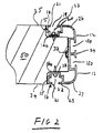
- Figure 2 depicts the manner in which the edge strip 10 may be secured to an edge face of a panel 50.
- the panel is rebated at both faces 34, 35 to accommodate flanges 14, 16 and position the external faces of the flanges 14a, 16a substantially flush with the panel faces.
- Fasteners such as the screws illustrated, are driven through from channels 28 so that their heads are seated in the channels.
- FIGs 3A-3C and 4 The manner in which edge strips of the forms shown in Figures 1 and 2 may be coupled together is illustrated in Figures 3A-3C and 4.
- undercut grooves 18, 20, 22 are similarly dimensioned to snugly and firmly receive longitudinal inserts 40 of similar uniform cross-section adapted to engage and secure together respective registering grooves on adjacent edge strips.
- two panels 50, 50' are fitted with strips edge 10, 10' and are butt joined to a pair of H- section inserts 40a, 40b passed along grooves 18a, 18b in the front portions 12, 12' of the panel edge strips 10, 10'.
- Figure 3B depicts a 90° join
- Figure 3C illustrates a mutual angular fixing using a V-shaped coupling insert 41.
- Inserts 40, 41 are typically extruded in a suitable plastics material e.g. Polyvinyl chloride (PVC).
- PVC Polyvinyl chloride
- Figure 4 shows two partition panels in position to be butt-joined, with the inserts 40a, 40b ready to be slid down the opposed grooves.
- the panels include cable ducts 51 at their lower ends.
- edge strip 10 The versatility of edge strip 10 is highlighted in Figure 5.
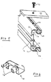
- An accessory base 60 is fastened to the strip by engagement of a screw 62 through the base 60 into a metal insert 62 slidably carried by groove 20.
- the position of the accessory can be varied along the groove by loosening the screw and moving the insert along the groove.
- Edge strips 12 may be closed at their ends by end caps 70 of the configuration depicted in Figure 6.
- the end cap 70 engages the edge strip by way of a pair of projecting hollow spigots 72 which are a close matching fit in the cavities 74 ( Figure 5) under corner webs 26, 27 ( Figure 1) between the adjacent side walls of grooves 20, 22.
- the external surfaces of the cap are designed to be flush with the corresponding surfaces of the edge strip.
- the end cap 70 may be secured into the end of the edge strip 12 by a fastener, for example a screw, which engages with C-section rib 32.
- Figure 7 depicts an especially versatile panel 50'' fitted at two edge faces 50a with edge strips 10'' and at the other two edge faces 50b with slotted strips 80. Opening at the lower longitudinal side edge 81 of strip 80 are a plurality of, in this case four, equi-spaced transversely extending slots 82. These slots are dimensioned to receive respective studs of another furniture component and extend about half way across the strip. In this manner panel 50'' may be supported by the furniture component bearing the studs. It will be noted that edge faces 50b are formed with sockets or notches 50c behind and in register with slots 82'' to seat the heads of the studs.
- Each slot 82 has a margin which is inclined with respect to the adjacent face of the strip so that the slot is correspondingly inclined.
- a suitable matching stud has an enlarged slotted head, a threaded shank, and an intermediate unthreaded portion which abuts the surface in which the stud is threaded and is complementary to the slots. This intermediate stud portion is of slightly less width than each slot and the inner end of each slot is curved to match the circumference of the intermediate stud portion.
Landscapes
- Engineering & Computer Science (AREA)
- Architecture (AREA)
- Physics & Mathematics (AREA)
- Electromagnetism (AREA)
- Civil Engineering (AREA)
- Structural Engineering (AREA)
- Furniture Connections (AREA)
Claims (13)
- Länglicher Kantenstreifen (10) für eine Platte (50), mit einem länglichen Vorderabschnitt (12) und Seitenabschnitten, wobei der Vorderabschnitt und zumindest einer der Seitenabschnitte jeweils eine hinterschnittene Vertiefung (18, 20, 22) hat, die sich längs zu dem Kantenstreifen erstreckt und dimensioniert ist, um satt Längseinsätze (40) aufzunehmen, um an ausgerichteten Vertiefungen von benachbarten Kantenstreifen anzugreifen und diese zusammen festzulegen, dadurch gekennzeichnet, daß die Seitenabschnitte durch jeweilige Flanschabschnitte (14, 16) ausgebildet sind, die an den Seiten des länglichen Vorderabschnittes derart angeordnet sind, daß der Kantenstreifen generell U-förmiger Konfiguration ist.
- Kantenstreifen nach Anspruch 1, wobei der Vorderabschnitt zwei der hinterschnittenen Vertiefungen (18a, 18b) hat.
- Kantenstreifen nach Anspruch 1 oder 2, wobei die hinterschnittenen Vertiefungen (18, 20, 22) von rechteckigem Querschnitt sind.
- Kantenstreifen nach Anspruch 1, 2 oder 3, wobei eine oder mehr der Vertiefungen einen Kanal (28) in ihrem Boden hat, um Befestigungselemente zum Anbringen des Kantenstreifens an einer Platte aufzunehmen.
- Kantenstreifen nach irgendeinem vorhergehenden Anspruch, wobei die Flanschabschnitte (14, 16) einstückig mit dem länglichen Vorderabschnitt durch jeweilige gekrümmte Stege (26, 27) verbunden sind.
- Kantenstreifen nach irgendeinem vorhergehenden Ansprüche mit einer Metallextrosion.
- Platte (50) mit zumindest einer Kante oder Kantenstirnfläche (50a), die mit einem Kantenstreifen (10) gemäß irgendeinem der vorhergehenden Ansprüche versehen ist.
- Platte nach Anspruch 7, wobei eine weitere Kante oder Kantenstirnseite (50b) mit einem länglichen Streifen (80) versehen ist, der jeweilige Längsseitenkanten (81) hat, wobei der Streifen eine Vielzahl von beabstandeten, sich quer erstreckenden Schlitzen oder Löchern (82) hat, die sich bei einer oder einer anderen der Seitenkanten öffnen, und zwar zum Aufnehmen von komplementären Bolzen.
- Platte nach Anspruch 8, die weiterhin einen Rand um jeden Schlitz (82) aufweist, der bezüglich der benachbarten Stirnseite des länglichen Streifens geneigt ist, wodurch der Schlitz entsprechend geneigt ist.
- Platte nach Anspruch 8 oder 9, wobei die Platte hinter dem mit Schlitzen versehenen länglichen Streifen geformte Buchsen (50c) hinter und in Ausrichtung mit den Schlitzen (82) hat, um die Bolzen aufzunehmen.
- Platte nach irgendeinem der Ansprüche 7 bis 10, versehen an zumindest einer weiteren Kante oder Kantenstirnfläche (50b) mit einem länglichen Streifen (80) mit jeweiligen Längsseitenkanten (81), wobei der längliche Streifen eine Vielzahl von beabstandeten, sich quer erstreckenden Schlitzen oder Löchern (82) hat, die sich an einer oder einer anderen der Seitenkanten öffnen, und zwar zum Aufnehmen von komplementären Bolzen.
- Platte nach Anspruch 11, die weiterhin einen Rand um jenen Schlitz (82) aufweist, der bezüglich der benachbarten Stirnseite des länglichen Streifens geneigt ist, wodurch der Schlitz entsprechend geneigt ist.
- Platte nach Anspruch 11 und 12, wobei die Platte geformte Buchsen (50c) hinter und in Ausrichtung mit den Schlitzen (82) hat, um die Bolzen aufzunehmen.
Applications Claiming Priority (2)
| Application Number | Priority Date | Filing Date | Title |
|---|---|---|---|
| AUPI726088 | 1988-03-15 | ||
| AU7260/88 | 1988-03-15 |
Publications (2)
| Publication Number | Publication Date |
|---|---|
| EP0333463A1 EP0333463A1 (de) | 1989-09-20 |
| EP0333463B1 true EP0333463B1 (de) | 1993-06-23 |
Family
ID=3772920
Family Applications (1)
| Application Number | Title | Priority Date | Filing Date |
|---|---|---|---|
| EP89302565A Expired - Lifetime EP0333463B1 (de) | 1988-03-15 | 1989-03-15 | Kantenstreifen für Platten |
Country Status (4)
| Country | Link |
|---|---|
| EP (1) | EP0333463B1 (de) |
| AU (1) | AU622641B2 (de) |
| DE (1) | DE68907242T2 (de) |
| MY (1) | MY108560A (de) |
Families Citing this family (8)
| Publication number | Priority date | Publication date | Assignee | Title |
|---|---|---|---|---|
| IT247890Y1 (it) * | 1999-01-25 | 2002-09-16 | Giuseppe Librizzi | Sistema di realizzazione dell'accoppiametno di tronconi di condotto diimpianti di condizionamento dell'aria nonche' elemento angolare |
| GB2349396B (en) * | 1999-04-28 | 2003-08-13 | Screen Solutions Ltd | Screen panel connectors |
| US6557955B2 (en) | 2001-01-13 | 2003-05-06 | Darren Saravis | Snap together modular storage |
| US7472969B2 (en) | 2001-01-13 | 2009-01-06 | Cube Concepts, Llc | Panel cover attachments to snap together connectors |
| RU2241806C2 (ru) * | 2002-10-10 | 2004-12-10 | Закрытое акционерное общество "НАЯДА" | Мобильная стеновая конструкция |
| RU2271421C2 (ru) * | 2004-05-06 | 2006-03-10 | Зао "Наяда" | Мобильная составная стеновая конструкция |
| RU2256753C1 (ru) * | 2004-11-23 | 2005-07-20 | Общество с ограниченной ответственностью "Строймода" | Стыковое соединение панелей ограждения с силовым упругим замыканием и замковый узел стыкового соединения панелей |
| CN102524097B (zh) * | 2011-12-31 | 2014-02-05 | 厦门吉信德宠物用品有限公司 | 用于组装宠物屋/家具/活动房的标准化组件 |
Family Cites Families (4)
| Publication number | Priority date | Publication date | Assignee | Title |
|---|---|---|---|---|
| DE2055800A1 (de) * | 1970-01-16 | 1971-07-22 | Gioia A | Verbindungsvorrichtung für Flachkorper |
| IT1079251B (it) * | 1977-06-24 | 1985-05-08 | Castelli Sas Anonima | Elementi modulari per la composizione di pareti armadi scrivante o altri articoli di arredamento di tipo scomponibile |
| GB2156206A (en) * | 1984-03-26 | 1985-10-09 | Standard Telephones Cables Ltd | Workstation |
| DE3614490A1 (de) * | 1986-04-29 | 1987-11-05 | Kueffner Reinhold Innenausbau | Grundrahmen und verbindungselemente fuer displaysysteme |
-
1988
- 1988-04-05 MY MYPI88000345A patent/MY108560A/en unknown
-
1989
- 1989-03-14 AU AU31317/89A patent/AU622641B2/en not_active Ceased
- 1989-03-15 DE DE89302565T patent/DE68907242T2/de not_active Expired - Fee Related
- 1989-03-15 EP EP89302565A patent/EP0333463B1/de not_active Expired - Lifetime
Also Published As
| Publication number | Publication date |
|---|---|
| MY108560A (en) | 1996-10-31 |
| AU3131789A (en) | 1989-09-21 |
| DE68907242T2 (de) | 1993-12-09 |
| AU622641B2 (en) | 1992-04-16 |
| EP0333463A1 (de) | 1989-09-20 |
| DE68907242D1 (de) | 1993-07-29 |
Similar Documents
| Publication | Publication Date | Title |
|---|---|---|
| EP0177639B1 (de) | Wandsystem | |
| US5694729A (en) | Wall partition connector | |
| US4120124A (en) | Movable wall assembly | |
| USRE32890E (en) | Frame connector system | |
| US4833848A (en) | Double panel assembly | |
| US4601137A (en) | Locking mechanism for an office panel system | |
| CA2272718C (en) | Knock-down portable partition system | |
| US4460147A (en) | Mounting brackets for shelves and panels | |
| US4126364A (en) | Connector for frame members | |
| US5803146A (en) | Modular partition system | |
| US3037593A (en) | Partition construction | |
| US3425171A (en) | Space divider system | |
| US5996299A (en) | Partition wall material | |
| US3925948A (en) | Modular wall construction | |
| GB2300867A (en) | Partition wall | |
| US3848364A (en) | Support structure for shelving | |
| US6047509A (en) | Corner support for panel frames | |
| JPH0574722B2 (de) | ||
| US4570402A (en) | Connector apparatus for modular panel structure | |
| US6230459B1 (en) | Wall start for panel systems | |
| EP0009991A1 (de) | Trennwandsystem mit vertikal verstellbarem Kopf- oder Fussteil | |
| EP0333463B1 (de) | Kantenstreifen für Platten | |
| US3925939A (en) | Support structure for shelving | |
| GB2083342A (en) | Frames for fitted furniture | |
| CA2106781C (en) | Partition frame structure |
Legal Events
| Date | Code | Title | Description |
|---|---|---|---|
| PUAI | Public reference made under article 153(3) epc to a published international application that has entered the european phase |
Free format text: ORIGINAL CODE: 0009012 |
|
| AK | Designated contracting states |
Kind code of ref document: A1 Designated state(s): DE FR GB |
|
| 17P | Request for examination filed |
Effective date: 19900302 |
|
| 17Q | First examination report despatched |
Effective date: 19910219 |
|
| GRAA | (expected) grant |
Free format text: ORIGINAL CODE: 0009210 |
|
| AK | Designated contracting states |
Kind code of ref document: B1 Designated state(s): DE FR GB |
|
| PG25 | Lapsed in a contracting state [announced via postgrant information from national office to epo] |
Ref country code: FR Effective date: 19930623 |
|
| REF | Corresponds to: |
Ref document number: 68907242 Country of ref document: DE Date of ref document: 19930729 |
|
| EN | Fr: translation not filed | ||
| PGFP | Annual fee paid to national office [announced via postgrant information from national office to epo] |
Ref country code: GB Payment date: 19940314 Year of fee payment: 6 |
|
| PLBE | No opposition filed within time limit |
Free format text: ORIGINAL CODE: 0009261 |
|
| STAA | Information on the status of an ep patent application or granted ep patent |
Free format text: STATUS: NO OPPOSITION FILED WITHIN TIME LIMIT |
|
| 26N | No opposition filed | ||
| PG25 | Lapsed in a contracting state [announced via postgrant information from national office to epo] |
Ref country code: GB Effective date: 19950315 |
|
| GBPC | Gb: european patent ceased through non-payment of renewal fee |
Effective date: 19950315 |
|
| PGFP | Annual fee paid to national office [announced via postgrant information from national office to epo] |
Ref country code: DE Payment date: 19960701 Year of fee payment: 8 |
|
| REG | Reference to a national code |
Ref country code: GB Ref legal event code: 728V |
|
| REG | Reference to a national code |
Ref country code: GB Ref legal event code: 7281 |
|
| PG25 | Lapsed in a contracting state [announced via postgrant information from national office to epo] |
Ref country code: DE Effective date: 19971202 |