EP0333391A2 - Flügelzellenpumpe - Google Patents
Flügelzellenpumpe Download PDFInfo
- Publication number
- EP0333391A2 EP0333391A2 EP89302398A EP89302398A EP0333391A2 EP 0333391 A2 EP0333391 A2 EP 0333391A2 EP 89302398 A EP89302398 A EP 89302398A EP 89302398 A EP89302398 A EP 89302398A EP 0333391 A2 EP0333391 A2 EP 0333391A2
- Authority
- EP
- European Patent Office
- Prior art keywords
- pump
- vane
- wheel
- vanes
- rotation axis
- Prior art date
- Legal status (The legal status is an assumption and is not a legal conclusion. Google has not performed a legal analysis and makes no representation as to the accuracy of the status listed.)
- Granted
Links
Images

Classifications
-
- F—MECHANICAL ENGINEERING; LIGHTING; HEATING; WEAPONS; BLASTING
- F04—POSITIVE - DISPLACEMENT MACHINES FOR LIQUIDS; PUMPS FOR LIQUIDS OR ELASTIC FLUIDS
- F04C—ROTARY-PISTON, OR OSCILLATING-PISTON, POSITIVE-DISPLACEMENT MACHINES FOR LIQUIDS; ROTARY-PISTON, OR OSCILLATING-PISTON, POSITIVE-DISPLACEMENT PUMPS
- F04C2/00—Rotary-piston machines or pumps
- F04C2/30—Rotary-piston machines or pumps having the characteristics covered by two or more groups F04C2/02, F04C2/08, F04C2/22, F04C2/24 or having the characteristics covered by one of these groups together with some other type of movement between co-operating members
- F04C2/34—Rotary-piston machines or pumps having the characteristics covered by two or more groups F04C2/02, F04C2/08, F04C2/22, F04C2/24 or having the characteristics covered by one of these groups together with some other type of movement between co-operating members having the movement defined in groups F04C2/08 or F04C2/22 and relative reciprocation between the co-operating members
- F04C2/344—Rotary-piston machines or pumps having the characteristics covered by two or more groups F04C2/02, F04C2/08, F04C2/22, F04C2/24 or having the characteristics covered by one of these groups together with some other type of movement between co-operating members having the movement defined in groups F04C2/08 or F04C2/22 and relative reciprocation between the co-operating members with vanes reciprocating with respect to the inner member
- F04C2/3441—Rotary-piston machines or pumps having the characteristics covered by two or more groups F04C2/02, F04C2/08, F04C2/22, F04C2/24 or having the characteristics covered by one of these groups together with some other type of movement between co-operating members having the movement defined in groups F04C2/08 or F04C2/22 and relative reciprocation between the co-operating members with vanes reciprocating with respect to the inner member the inner and outer member being in contact along one line or continuous surface substantially parallel to the axis of rotation
Definitions
- the present invention relates to a vane pump for working with relatively low rotary speed, which pump consists of a pump housing (with an inlet port and an outlet port), where in said pump housing is fitted a rotatable seated pump wheel with its rotation axis placed eccentric in relation to the interior of the pump housing.
- the pump wheel is equipped with two radially slidable vanes, which vanes may be movable in relation to the pump wheel between two extreme positions dependent on the shape and siting internally in the pump housing of the parts designed to support the edges of the vanes.
- low rotary speed is meant that the pump wheel during normal operation makes less than 100 revolutions per minute.
- This type of pump is disclosed in DK patent publication no. 139.880 and is designed for the transport of whole fish in water.
- the known pump is thus designed to transport solid parts suspended in liquid in a gentle manner.
- the known pump has a large capacity in relation til its external measurements. It is, however, not particularly robust as a movable valve flap which lies up against the pump wheel, thus forming packing between the casing and the wheel, has a tendency to jam due to impurities in the liquid.
- the vanes slide in relation to the pump wheel. This causes extensive wear on the vanes and hereby considerable maintenance.
- the aim of this present invention is to produce a rotating positive-displacement type pump of the above-mentioned kind, which compared to the known pumps has a more robust and maintenance-free construction for pumping tasks demanding large torque, and especially for pumping sluggish or highly viscous mediums or pumping at high pumping pressures.
- vanes each stretch diametrically through the pump wheel and are essentially at right-angles to one another, that the parts guiding the vane edges are shaped as to define circular arc-sections of travel for the vane edges with centre in the rotation axis of the wheel in at least one section between the inlet port and the outlet port, the section covering an angle of at least 90° as seen parallel to the rotation axis.
- the vanes reach out to the pump housing sides on each side of the wheel and are guided by parts, i.e. surfaces or rails, which stretch round the wheel.
- the actual pump pressure can thereby be built up in this section and as the surfaces in this section are concentric with the wheel's rotation axis, the vanes will not move in relation to the wheel during passage through these sections. In this way, one entirely avoids the wear caused by movement between wheel and vane in precisely this area, where the load exercised on the pump medium by the vanes, and, therefore, also by the wheel on the vanes, is greatest.
- highly viscous mediums can be pumped and the possibility of high pump pressure is treated at the same time as the gentle treatment of the pump medium in such a slowly rotating positive-displacement pump with great internal volume is retained.
- Typical areas of use for the pump according to this invention are pump mediums such as slaughter-house waste, which up to now has been transported in open screw pumps with the subsequent nuisance of unpleasant smells, and floculated waste water which requires careful treatment so as not to break up the floculated lumps of solid material in the water, and for which piston pumps have been used up to now.
- pump mediums such as slaughter-house waste, which up to now has been transported in open screw pumps with the subsequent nuisance of unpleasant smells, and floculated waste water which requires careful treatment so as not to break up the floculated lumps of solid material in the water, and for which piston pumps have been used up to now.
- the vane edges can, as dealt with in claim 4, consist of detachable fixed pieces.
- the removable vane edges can be made shock-absorbent by means of a shock-absorbing liner, the purpose being to counteract hard particles in the pumping medium.
- the liner can thus act as a compression spring so the vane edges are always held pressed against the bars or surfaces along which the vane edges slide.
- the pump according to this invention When the pump according to this invention is needed for pumping mediums with low viscosity it can be made as dealt with in claim 6, where the circular arc-shaped section and, at least the adjoining and toward the rotation axis extended surfaces inside the pump housing, are mainly coated with a relatively flexible material, for example plastic or rubber material.
- a relatively flexible material for example plastic or rubber material.
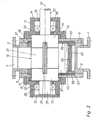
- a preferred embodiment of the pump according to this invention has a mounting flange or foot 1, whereon a cast pump housing 3 is fixed.
- the pump housing 3 has a rectangularly shaped, radially directed inlet 5, a tangential directed outlet 7 and an internal form like a cylinder.
- covers 9 are mounted by screws, on which covers 9 bearing housings 11 are eccentrically mounted, the housings 11 being closed with end covers 13 and 14.
- the pump has a pump wheel 15 which in this embodiment consists of two end pieces 17 and 19 and a middle piece 21. As shown on fig. 1 this middle piece 21 is divided into four quarter parts. All three pieces 17, 19, 21 are made of a solid material and are mutually connected with screws, the fitting screw holes 23 being shown on fig. 1.
- the end pieces 17 and 19 are made in one piece with an axle journal 25 and a drive axle 27, respectively, both of which rest in bearings 29 in the bearing housings 11.
- a hole in the cover 14 allows passage of the drive axle 27 which is driven by a not shown hydraulic motor.
- packings 31 are fitted to prevent the pump medium leaving the pump housing 3, and packings 33 and 35 are fitted to protect the bearings 29.
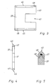
- Each vane 37 is thus cut oute of a solid sheet in a U-shape with a cut-out 41 which stretches from the one side edge 43 of the vane to a depth a little over half the width of the vane.
- the radially facing edges 45 of the vanes are fitted with detachable pieces 47 fixed with counter-sunk screws 48 to the web of the vane 37.
- a flexible liner 49 which for example may be of solid rubber and shaped as shown on fig. 5.
- Replaceable wear irons 39 control the vanes in the wheel 15, the rotation axis 51 of which is in a first plane of symmetry 53 to the pump housing's interior and at a distance from a second plane of symmetry 55.
- the vane's 37 position in relation to the wheel 15 is controlled by rails 57, the surfaces of which have three different radiuses of curvature. The smallest radius is determined by the radiuses of end pieces 17 and 19, as these lie close up against bars 57 in area 59. The remaining radiuses and sitings of the rail surfaces in areas 61 and 63 are determined by area 59, as the height and rotation axis siting of the vanes determines these.
- area 63 a semi-cylindrical curve is formed, with its centre in rotation axis 51 and in area 61 the curve is fixed as a transition between areas 59 and 61.
- this deflector 66 keeps impurities from wedging themselves between the rotor 15 and the surface 59 and supports packing 65, all at the same time.
- elements 65 stretch over a circular arc a little larger than 90°, at the same time the middle section 21 of the rotor, which has a little larger diameter than the end pieces 17 and 19, always lies up against the corresponding element 65 in area 59.
- the pump can pump water with greater difference pressure over the pump, even at rotary speeds less than 70 rpm.
- the low rotary speed of the pump and resulting gentle treatment of the pump medium particularly prove their worth when one wants to transport floculated waste water without spoiling the floculated lumps of solid material in the water.
- the pump may as shown by the stippled line on fig. 1 be equipped with a knife 71 which stretches across inlet 5.
- the knife 71 is provided with an edge 73 of hardened steel; this edge is placed between bars 57 close to the track created by vane edges 45 during the movement of the wheel 15. If, for example, a piece of rib gets stuck between vane edge 45 and the knife edge 73 this will simply be cut over.
- packings 65 and 68 can be dispensed with, as a gap of a few hundredths of a millimeter between surfaces 59, 63, 69 and vane edges 45 is adequate to maintain the pump outlet pressure.
- the robust and simple construction obtained with the pump according to this invention is also useful in other areas, for example, for transporting highly viscous liquids and liquids which are difficult to handle.
- the pump construction can thus withstand heating, a property which can be utilized when pumping raw oil in refineries.
Landscapes
- Engineering & Computer Science (AREA)
- Mechanical Engineering (AREA)
- General Engineering & Computer Science (AREA)
- Rotary Pumps (AREA)
- Structures Of Non-Positive Displacement Pumps (AREA)
Priority Applications (1)
| Application Number | Priority Date | Filing Date | Title |
|---|---|---|---|
| AT89302398T ATE89893T1 (de) | 1988-03-16 | 1989-03-10 | Fluegelzellenpumpe. |
Applications Claiming Priority (4)
| Application Number | Priority Date | Filing Date | Title |
|---|---|---|---|
| DK144188A DK169769B1 (da) | 1988-03-16 | 1988-03-16 | Fortrængningspumpe samt anvendelse af denne |
| DK1441/88 | 1988-03-16 | ||
| DK657488A DK657488D0 (da) | 1988-11-25 | 1988-11-25 | Lamelpumpe |
| DK6574/88 | 1988-11-25 |
Publications (3)
| Publication Number | Publication Date |
|---|---|
| EP0333391A2 true EP0333391A2 (de) | 1989-09-20 |
| EP0333391A3 EP0333391A3 (en) | 1990-01-17 |
| EP0333391B1 EP0333391B1 (de) | 1993-05-26 |
Family
ID=26065754
Family Applications (1)
| Application Number | Title | Priority Date | Filing Date |
|---|---|---|---|
| EP19890302398 Expired - Lifetime EP0333391B1 (de) | 1988-03-16 | 1989-03-10 | Flügelzellenpumpe |
Country Status (2)
| Country | Link |
|---|---|
| EP (1) | EP0333391B1 (de) |
| DE (1) | DE68906693D1 (de) |
Cited By (7)
| Publication number | Priority date | Publication date | Assignee | Title |
|---|---|---|---|---|
| WO1993008403A1 (en) * | 1991-10-25 | 1993-04-29 | Southern Group Limited | Vane pump |
| WO1995009973A1 (en) * | 1993-10-01 | 1995-04-13 | COOTE, Paul, Gregory | Positive displacement pump apparatus |
| FR2757575A1 (fr) * | 1996-12-24 | 1998-06-26 | Atochem Elf Sa | Pompe a palettes pour le transfert d'un fluide inflammable et en particulier un gaz liquefie |
| WO1998042984A1 (en) * | 1997-03-24 | 1998-10-01 | Baker Medical Research Institute | Positive displacement pump |
| GB2389875A (en) * | 2002-06-21 | 2003-12-24 | Boc Group Plc | Vane pump with a non-circular bore |
| US7258535B2 (en) * | 2004-03-23 | 2007-08-21 | Brother Kogyo Kabushiki Kaisha | Sealing features for a pump and ink jet printer mounting the pump |
| WO2025056632A1 (en) * | 2023-09-13 | 2025-03-20 | Haarslev Industries A/S | Improved vane for a rotary vane pump |
Families Citing this family (1)
| Publication number | Priority date | Publication date | Assignee | Title |
|---|---|---|---|---|
| SE9804317D0 (sv) * | 1998-12-15 | 1998-12-15 | Gunnar Bjoerk | Pulspump |
Citations (2)
| Publication number | Priority date | Publication date | Assignee | Title |
|---|---|---|---|---|
| US1943561A (en) | 1932-07-06 | 1934-01-16 | Nat Transit Pump & Machine Com | Blade for rotary pumps |
| DE1043230B (de) | 1956-03-31 | 1958-11-06 | Egyesuelt Izzolampa | Hydraulische Maschine |
Family Cites Families (4)
| Publication number | Priority date | Publication date | Assignee | Title |
|---|---|---|---|---|
| FR386967A (fr) * | 1907-04-25 | 1908-06-27 | Jean Nepomucene Hochgesand | Dispositif pouvant etre utilisé comme pompe ou moteur rotatif |
| US2495771A (en) * | 1945-10-15 | 1950-01-31 | Richer Ella | Diametrically cooperating vane pump |
| FR2504609B1 (fr) * | 1981-04-27 | 1986-11-21 | Sulzer Ag | Palette destinee a equiper un dispositif hydraulique rotatif |
| US4561834A (en) * | 1983-07-13 | 1985-12-31 | Poss Design Limited | Rotary vaned pumps with fixed length and shearing knife-edged vanes |
-
1989
- 1989-03-10 DE DE8989302398T patent/DE68906693D1/de not_active Expired - Lifetime
- 1989-03-10 EP EP19890302398 patent/EP0333391B1/de not_active Expired - Lifetime
Patent Citations (2)
| Publication number | Priority date | Publication date | Assignee | Title |
|---|---|---|---|---|
| US1943561A (en) | 1932-07-06 | 1934-01-16 | Nat Transit Pump & Machine Com | Blade for rotary pumps |
| DE1043230B (de) | 1956-03-31 | 1958-11-06 | Egyesuelt Izzolampa | Hydraulische Maschine |
Cited By (9)
| Publication number | Priority date | Publication date | Assignee | Title |
|---|---|---|---|---|
| WO1993008403A1 (en) * | 1991-10-25 | 1993-04-29 | Southern Group Limited | Vane pump |
| WO1995009973A1 (en) * | 1993-10-01 | 1995-04-13 | COOTE, Paul, Gregory | Positive displacement pump apparatus |
| US5795143A (en) * | 1993-10-01 | 1998-08-18 | Qvp Pty Ltd. | Positive displacement pump apparatus |
| US5911567A (en) * | 1993-10-01 | 1999-06-15 | Qvp Pty Ltd | Positive displacement pump apparatus |
| FR2757575A1 (fr) * | 1996-12-24 | 1998-06-26 | Atochem Elf Sa | Pompe a palettes pour le transfert d'un fluide inflammable et en particulier un gaz liquefie |
| WO1998042984A1 (en) * | 1997-03-24 | 1998-10-01 | Baker Medical Research Institute | Positive displacement pump |
| GB2389875A (en) * | 2002-06-21 | 2003-12-24 | Boc Group Plc | Vane pump with a non-circular bore |
| US7258535B2 (en) * | 2004-03-23 | 2007-08-21 | Brother Kogyo Kabushiki Kaisha | Sealing features for a pump and ink jet printer mounting the pump |
| WO2025056632A1 (en) * | 2023-09-13 | 2025-03-20 | Haarslev Industries A/S | Improved vane for a rotary vane pump |
Also Published As
| Publication number | Publication date |
|---|---|
| DE68906693D1 (en) | 1993-07-01 |
| EP0333391A3 (en) | 1990-01-17 |
| EP0333391B1 (de) | 1993-05-26 |
Similar Documents
| Publication | Publication Date | Title |
|---|---|---|
| US6053717A (en) | Rotary pump with wiper insert | |
| EP0333391B1 (de) | Flügelzellenpumpe | |
| EA001252B1 (ru) | Насос центробежного или полуосевого типа | |
| US5302082A (en) | Improved efficiency grinding pump for slurry | |
| EP0134636B1 (de) | Drehschieberpumpen | |
| RU2060827C1 (ru) | Устройство для транспортировки, размельчения и перемешивания материала с содержанием и без содержания твердых веществ | |
| WO1994001218A9 (en) | Grinding pump | |
| US4123205A (en) | Rotary vane pump with sealing means | |
| US4984975A (en) | Rotary pump with cutting means | |
| US5567140A (en) | Keyed insert plate for curved rotary lobe pump chamber walls | |
| US5318415A (en) | Grooved pump chamber walls for flushing fiber deposits | |
| EP3271585B1 (de) | Wartungsfreundlich konstruierte taumelscheibenpumpe | |
| US4298161A (en) | Centrifuge | |
| US4407509A (en) | Zero-leakage non-contacting mechanical face seal for rotary machines | |
| US2626571A (en) | Rotary positive displacement pump | |
| US805552A (en) | Rotary pump. | |
| AU700197B2 (en) | Swash plate machine | |
| RU2056537C1 (ru) | Жидкостно-кольцевая машина | |
| US3240155A (en) | Helical rotary pumps | |
| RU2082020C1 (ru) | Роторная объемная гидропневмомашина | |
| EP3287593B1 (de) | Flügelzellenpumpe | |
| US1652609A (en) | Positive pressure blower and vacuum pump | |
| JPH0663508B2 (ja) | 破砕ポンプ | |
| DE2403011A1 (de) | Fluegelzellenmaschine | |
| US2995093A (en) | Rotary pump |
Legal Events
| Date | Code | Title | Description |
|---|---|---|---|
| PUAI | Public reference made under article 153(3) epc to a published international application that has entered the european phase |
Free format text: ORIGINAL CODE: 0009012 |
|
| AK | Designated contracting states |
Kind code of ref document: A2 Designated state(s): AT BE CH DE ES FR GB GR IT LI LU NL SE |
|
| PUAL | Search report despatched |
Free format text: ORIGINAL CODE: 0009013 |
|
| AK | Designated contracting states |
Kind code of ref document: A3 Designated state(s): AT BE CH DE ES FR GB GR IT LI LU NL SE |
|
| 17P | Request for examination filed |
Effective date: 19900613 |
|
| 17Q | First examination report despatched |
Effective date: 19910731 |
|
| GRAA | (expected) grant |
Free format text: ORIGINAL CODE: 0009210 |
|
| AK | Designated contracting states |
Kind code of ref document: B1 Designated state(s): AT BE CH DE ES FR GB GR IT LI LU NL SE |
|
| PG25 | Lapsed in a contracting state [announced via postgrant information from national office to epo] |
Ref country code: IT Free format text: LAPSE BECAUSE OF FAILURE TO SUBMIT A TRANSLATION OF THE DESCRIPTION OR TO PAY THE FEE WITHIN THE PRE;WARNING: LAPSES OF ITALIAN PATENTS WITH EFFECTIVE DATE BEFORE 2007 MAY HAVE OCCURRED AT ANY TIME BEFORE 2007. THE CORRECT EFFECTIVE DATE MAY BE DIFFERENT FROM THE ONE RECORDED.SCRIBED TIME-LIMIT Effective date: 19930526 Ref country code: DE Effective date: 19930526 Ref country code: NL Effective date: 19930526 Ref country code: LI Effective date: 19930526 Ref country code: FR Effective date: 19930526 Ref country code: AT Effective date: 19930526 Ref country code: CH Effective date: 19930526 Ref country code: ES Free format text: THE PATENT HAS BEEN ANNULLED BY A DECISION OF A NATIONAL AUTHORITY Effective date: 19930526 Ref country code: BE Effective date: 19930526 Ref country code: GR Free format text: LAPSE BECAUSE OF FAILURE TO SUBMIT A TRANSLATION OF THE DESCRIPTION OR TO PAY THE FEE WITHIN THE PRESCRIBED TIME-LIMIT Effective date: 19930526 Ref country code: SE Effective date: 19930526 |
|
| REF | Corresponds to: |
Ref document number: 89893 Country of ref document: AT Date of ref document: 19930615 Kind code of ref document: T |
|
| REF | Corresponds to: |
Ref document number: 68906693 Country of ref document: DE Date of ref document: 19930701 |
|
| REG | Reference to a national code |
Ref country code: CH Ref legal event code: PL |
|
| EN | Fr: translation not filed | ||
| NLV1 | Nl: lapsed or annulled due to failure to fulfill the requirements of art. 29p and 29m of the patents act | ||
| PG25 | Lapsed in a contracting state [announced via postgrant information from national office to epo] |
Ref country code: GB Effective date: 19940310 |
|
| PG25 | Lapsed in a contracting state [announced via postgrant information from national office to epo] |
Ref country code: LU Free format text: LAPSE BECAUSE OF NON-PAYMENT OF DUE FEES Effective date: 19940331 |
|
| PLBE | No opposition filed within time limit |
Free format text: ORIGINAL CODE: 0009261 |
|
| STAA | Information on the status of an ep patent application or granted ep patent |
Free format text: STATUS: NO OPPOSITION FILED WITHIN TIME LIMIT |
|
| 26N | No opposition filed | ||
| GBPC | Gb: european patent ceased through non-payment of renewal fee |
Effective date: 19940310 |