EP0332974B1 - Protection contre les court-circuits pour un convertisseur d'impulsions alimentant une macine électriqe utilisée aussi bien en génératrice qu'en réceptrice - Google Patents
Protection contre les court-circuits pour un convertisseur d'impulsions alimentant une macine électriqe utilisée aussi bien en génératrice qu'en réceptrice Download PDFInfo
- Publication number
- EP0332974B1 EP0332974B1 EP89103920A EP89103920A EP0332974B1 EP 0332974 B1 EP0332974 B1 EP 0332974B1 EP 89103920 A EP89103920 A EP 89103920A EP 89103920 A EP89103920 A EP 89103920A EP 0332974 B1 EP0332974 B1 EP 0332974B1
- Authority
- EP
- European Patent Office
- Prior art keywords
- circuit
- short
- circuit protection
- current
- pulse converter
- Prior art date
- Legal status (The legal status is an assumption and is not a legal conclusion. Google has not performed a legal analysis and makes no representation as to the accuracy of the status listed.)
- Expired - Lifetime
Links
- 239000004065 semiconductor Substances 0.000 claims description 10
- 239000003990 capacitor Substances 0.000 claims description 8
- 238000012806 monitoring device Methods 0.000 claims description 6
- 239000008186 active pharmaceutical agent Substances 0.000 claims description 3
- 230000001681 protective effect Effects 0.000 claims description 2
- 238000012544 monitoring process Methods 0.000 description 2
- 230000000903 blocking effect Effects 0.000 description 1
- 230000003247 decreasing effect Effects 0.000 description 1
- 230000001419 dependent effect Effects 0.000 description 1
- 238000011144 upstream manufacturing Methods 0.000 description 1
Images
Classifications
-
- H—ELECTRICITY
- H02—GENERATION; CONVERSION OR DISTRIBUTION OF ELECTRIC POWER
- H02H—EMERGENCY PROTECTIVE CIRCUIT ARRANGEMENTS
- H02H7/00—Emergency protective circuit arrangements specially adapted for specific types of electric machines or apparatus or for sectionalised protection of cable or line systems, and effecting automatic switching in the event of an undesired change from normal working conditions
- H02H7/08—Emergency protective circuit arrangements specially adapted for specific types of electric machines or apparatus or for sectionalised protection of cable or line systems, and effecting automatic switching in the event of an undesired change from normal working conditions for dynamo-electric motors
- H02H7/0833—Emergency protective circuit arrangements specially adapted for specific types of electric machines or apparatus or for sectionalised protection of cable or line systems, and effecting automatic switching in the event of an undesired change from normal working conditions for dynamo-electric motors for electric motors with control arrangements
- H02H7/0838—Emergency protective circuit arrangements specially adapted for specific types of electric machines or apparatus or for sectionalised protection of cable or line systems, and effecting automatic switching in the event of an undesired change from normal working conditions for dynamo-electric motors for electric motors with control arrangements with H-bridge circuit
Definitions
- the invention relates to short-circuit protection for a motor-driven and generator-operated pulse converter-fed electrical machine, i.e. a machine which is operational in all four quadrants of the speed-torque level and which is switched off from the external power supply in the event of a short circuit on the direct current feed.
- a motor-driven and generator-operated pulse converter-fed electrical machine i.e. a machine which is operational in all four quadrants of the speed-torque level and which is switched off from the external power supply in the event of a short circuit on the direct current feed.
- the object of the invention is therefore to provide a safe short-circuit protection for an above-mentioned pulse converter-fed electrical machine with fast-acting, not subject to exchange means, provided that the pulse converter usually contains an intermediate circuit capacitor and freewheeling diodes to the individual controllable semiconductors of the pulse converter.
- An additional measure according to claim 2 is provided to prevent switching overvoltages due to rapid current changes in the inductances of the direct current feed lines.
- Transistors, GTOs or similarly acting electronic switching means can be used as switchable antiparallel power semiconductors which are switched dependent on an electronic monitoring device which, for example, performs U CE monitoring of a transistor.
- the monitoring device is electrically connected to at least one of the direct current feed lines, so that it can detect a short circuit on the supply side.
- an additional diode is connected before the anti-parallel connection between the two direct current leads, through which no current can normally flow.
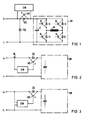
- An electrical machine M which can be operated in all quadrants of the speed-torque level is arranged in the bridge branch of a pulse converter UR with four controllable semiconductors H, freewheeling diodes D associated therewith and an upstream common intermediate circuit capacitor C. This arrangement is connected to a DC supply, not shown, via DC supply lines L + and L-.
- a protective diode DS which is polarized permeable during motor operation of the machine M is arranged in front of the pulse converter UR together with the intermediate circuit capacitor C, which is bridged by a controllable power semiconductor HS with the opposite direction of current flow (anti-parallel connection), so that Both a motor current and a generator current of the machine M can flow if the DC supply is faultless.
- the intermediate circuit capacitor C would discharge without the short-circuit protection via the short-circuit point between L + and L- and a machine short-circuit current could develop due to the then decreasing capacitor voltage via the freewheeling diodes D.
- the short-circuit protection has a quick-release monitoring device EW for the power semiconductor HS of the anti-parallel connection, which is connected in the area of the anti-parallel connection to the relevant DC supply line L + and detects a short circuit in the DC supply by monitoring the U CE voltage of the power semiconductor (transistor) HS and gives a blocking command to the power semiconductor HS in the event of a short-circuit in the direct current supply within microseconds before the short-circuit current can rise to a dangerous value. This prevents a noticeable discharge of the intermediate circuit capacitor C and thus a machine short-circuit current.
- the monitoring device EW can also be connected to a DC supply line via a current transformer W and connected to the power semiconductor HS, or the monitoring device EW can be galvanically connected to both DC supply lines according to FIG. 3.
- a diode Dp is provided between the direct current leads L + and L- in connection with the anti-parallel circuit HS, DS.
Landscapes
- Inverter Devices (AREA)
- Protection Of Static Devices (AREA)
- Emergency Protection Circuit Devices (AREA)
- Protection Of Generators And Motors (AREA)
- Control Of Ac Motors In General (AREA)
Claims (2)
- Dispositif de protection contre les court-circuits pour une machine électrique (M) alimentée par un convertisseur d'impulsions et pouvant fonctionner dans l'ensemble des quadrants du champ de caractéristiques vitesse de rotation-couple,
caractérisé par le fait
que dans une ligne (L+/-)-d'alimentation en courant continu est disposé un circuit antiparallèle formé d'une diode de protection (DS) polarisée de manière à laisser passer uniquement le courant de la machine fonctionnant en moteur, et un semiconducteur de puissance commandable (HS), qui laisse passer uniquement le courant de la machine fonctionnant en génératrice et qui est lié, selon une liaison de dépendance dans le sens de la coupure, à un dispositif de contrôle (EW) à déclenchement rapide, qui détecte un court-circuit dans le système d'alimentation en courant continu, de sorte qu'un condensateur intercalaire (C) du convertisseur d'impulsions (UR) est séparé du point de court-circuit dans le système d'alimentation en courant continu et que la tension du condensateur intermédiaire (C) bloque un courant de court-circuit de la machine au moyen des diodes à effet unidirectionnel (D) du convertisseur (UR). - Dispositif de protection contre des court-circuits suivant la revendication 1, caractérisé par le fait qu'une diode (Dp) est montée dans la zone de raccordement du circuit antiparallèle entre les deux lignes d'alimentation en courant continu (L+, L-).
Applications Claiming Priority (2)
| Application Number | Priority Date | Filing Date | Title |
|---|---|---|---|
| DE3809203 | 1988-03-18 | ||
| DE3809203 | 1988-03-18 |
Publications (2)
| Publication Number | Publication Date |
|---|---|
| EP0332974A1 EP0332974A1 (fr) | 1989-09-20 |
| EP0332974B1 true EP0332974B1 (fr) | 1992-10-14 |
Family
ID=6350135
Family Applications (1)
| Application Number | Title | Priority Date | Filing Date |
|---|---|---|---|
| EP89103920A Expired - Lifetime EP0332974B1 (fr) | 1988-03-18 | 1989-03-06 | Protection contre les court-circuits pour un convertisseur d'impulsions alimentant une macine électriqe utilisée aussi bien en génératrice qu'en réceptrice |
Country Status (7)
| Country | Link |
|---|---|
| US (1) | US4890181A (fr) |
| EP (1) | EP0332974B1 (fr) |
| JP (1) | JP3040782B2 (fr) |
| AU (1) | AU607847B2 (fr) |
| BR (1) | BR8901230A (fr) |
| CA (1) | CA1302482C (fr) |
| DE (1) | DE58902444D1 (fr) |
Cited By (1)
| Publication number | Priority date | Publication date | Assignee | Title |
|---|---|---|---|---|
| CN102045022A (zh) * | 2009-11-16 | 2011-05-04 | 孙宏斌 | 单相交流电动机无级调速电路 |
Families Citing this family (5)
| Publication number | Priority date | Publication date | Assignee | Title |
|---|---|---|---|---|
| DE19736903A1 (de) * | 1997-08-25 | 1999-03-04 | Asea Brown Boveri | Umrichter mit Gleichspannungszwischenkreis sowie Verfahren zum Betrieb eines solchen Umrichters |
| US7516325B2 (en) * | 2001-04-06 | 2009-04-07 | Certicom Corp. | Device authentication in a PKI |
| JP2002330593A (ja) * | 2001-05-07 | 2002-11-15 | Toshiba Corp | 電力変換装置 |
| US7031132B1 (en) | 2002-06-14 | 2006-04-18 | Mitchell Dennis A | Short circuit diagnostic tool |
| GB0221154D0 (en) * | 2002-09-12 | 2002-10-23 | Switched Reluctance Drives Ltd | A circuit for use with switched reluctance machines |
Family Cites Families (5)
| Publication number | Priority date | Publication date | Assignee | Title |
|---|---|---|---|---|
| DE3037305C2 (de) * | 1980-10-02 | 1986-04-03 | Flowtec AG, Reinach, Basel | Anordnung zur Erzeugung magnetischer Gleichfelder wechselnder Polarität für die magnetisch-induktive Durchflußmessung |
| US4410935A (en) * | 1981-03-23 | 1983-10-18 | General Signal Corporation | Current overload protection for inverter of uninterruptible power supply system |
| JPS57208894A (en) * | 1981-06-16 | 1982-12-22 | Fanuc Ltd | Controlling system for induction motor |
| JPS58207882A (ja) * | 1982-05-26 | 1983-12-03 | Fanuc Ltd | 交流モ−タの回生エネルギ−処理装置 |
| FR2577079B1 (fr) * | 1985-01-31 | 1987-02-27 | Option | Source de courant auxiliaire pour circuit d'alimentation a decoupage |
-
1989
- 1989-03-06 EP EP89103920A patent/EP0332974B1/fr not_active Expired - Lifetime
- 1989-03-06 DE DE8989103920T patent/DE58902444D1/de not_active Expired - Lifetime
- 1989-03-08 US US07/320,394 patent/US4890181A/en not_active Expired - Lifetime
- 1989-03-15 JP JP1063409A patent/JP3040782B2/ja not_active Expired - Lifetime
- 1989-03-16 CA CA000593971A patent/CA1302482C/fr not_active Expired - Fee Related
- 1989-03-17 AU AU31453/89A patent/AU607847B2/en not_active Ceased
- 1989-03-17 BR BR898901230A patent/BR8901230A/pt not_active IP Right Cessation
Cited By (2)
| Publication number | Priority date | Publication date | Assignee | Title |
|---|---|---|---|---|
| CN102045022A (zh) * | 2009-11-16 | 2011-05-04 | 孙宏斌 | 单相交流电动机无级调速电路 |
| CN102045022B (zh) * | 2009-11-16 | 2013-06-05 | 孙宏斌 | 单相交流电动机无级调速电路 |
Also Published As
| Publication number | Publication date |
|---|---|
| US4890181A (en) | 1989-12-26 |
| AU607847B2 (en) | 1991-03-14 |
| AU3145389A (en) | 1989-09-21 |
| DE58902444D1 (de) | 1992-11-19 |
| BR8901230A (pt) | 1989-11-07 |
| EP0332974A1 (fr) | 1989-09-20 |
| CA1302482C (fr) | 1992-06-02 |
| JP3040782B2 (ja) | 2000-05-15 |
| JPH01274622A (ja) | 1989-11-02 |
Similar Documents
| Publication | Publication Date | Title |
|---|---|---|
| DE3036619C2 (de) | Schaltungsanordnung für den Kurzschlußschutz von Transistoren | |
| DE69508644T2 (de) | Halbleiter-Leistungsmodul und -Leistungswandlervorrichtung | |
| DE69025045T2 (de) | Leistungswandler vom Brückentyp mit verbessertem Wirkungsgrad | |
| DE112017007140T5 (de) | Halbleitervorrichtung und Leistungsumwandlungssystem | |
| DE19702134A1 (de) | Schutzschaltung für Hochleistungs-Schalterbauteile | |
| EP0332974B1 (fr) | Protection contre les court-circuits pour un convertisseur d'impulsions alimentant une macine électriqe utilisée aussi bien en génératrice qu'en réceptrice | |
| WO2009043186A2 (fr) | Système de protection contre les courts-circuits de redresseurs à circuit intermédiaire de tension | |
| DE19736904A1 (de) | Stromrichterschaltungsanordnung | |
| DE69103358T2 (de) | Leistungswandler mit Querstrom-Schutz. | |
| DE69113575T2 (de) | Leistungsumwandlungsvorrichtung. | |
| EP0203571B1 (fr) | Onduleur statique avec surélévation de courant en cas de court-circuit | |
| DE3032328A1 (de) | Ueberstromschutzschaltung | |
| DE69534981T2 (de) | Fehlerdetektor für selbstgeführten spannungsquelle-leistungswandler | |
| AT409318B (de) | Schutzschaltung für eine netzgeführte thyristorbrücke | |
| DE10149581B4 (de) | Halbleitervorrichtung | |
| DE4037348C1 (en) | Protective circuitry for power semiconductor switches - uses bridging voltage clamping circuit consisting of diode and Zener diode belonging to rectifier pair | |
| EP0751611B1 (fr) | Convertisseur de puissance | |
| DE69322980T2 (de) | Halbleiter-Umwandlungsvorrichtung | |
| DE2801844C2 (fr) | ||
| DE2632381B2 (de) | Wechselrichterschaltung | |
| DE3801327C2 (fr) | ||
| DE19833551A1 (de) | Stromversorgungseinrichtung für eine Last | |
| EP0667986B1 (fr) | Dispositif permettant de proteger un onduleur | |
| DE4218749C2 (de) | Verfahren zur Steuerung eines Dreipunktwechselrichters | |
| EP0592696A1 (fr) | Circuit de protection pour une branche d'onduleur |
Legal Events
| Date | Code | Title | Description |
|---|---|---|---|
| PUAI | Public reference made under article 153(3) epc to a published international application that has entered the european phase |
Free format text: ORIGINAL CODE: 0009012 |
|
| AK | Designated contracting states |
Kind code of ref document: A1 Designated state(s): CH DE FR GB IT LI NL SE |
|
| 17P | Request for examination filed |
Effective date: 19891010 |
|
| 17Q | First examination report despatched |
Effective date: 19920325 |
|
| GRAA | (expected) grant |
Free format text: ORIGINAL CODE: 0009210 |
|
| AK | Designated contracting states |
Kind code of ref document: B1 Designated state(s): CH DE FR GB IT LI NL SE |
|
| REF | Corresponds to: |
Ref document number: 58902444 Country of ref document: DE Date of ref document: 19921119 |
|
| ET | Fr: translation filed | ||
| ITF | It: translation for a ep patent filed | ||
| GBT | Gb: translation of ep patent filed (gb section 77(6)(a)/1977) |
Effective date: 19930107 |
|
| PLBE | No opposition filed within time limit |
Free format text: ORIGINAL CODE: 0009261 |
|
| STAA | Information on the status of an ep patent application or granted ep patent |
Free format text: STATUS: NO OPPOSITION FILED WITHIN TIME LIMIT |
|
| 26N | No opposition filed | ||
| EAL | Se: european patent in force in sweden |
Ref document number: 89103920.8 |
|
| PGFP | Annual fee paid to national office [announced via postgrant information from national office to epo] |
Ref country code: NL Payment date: 19950331 Year of fee payment: 7 |
|
| PG25 | Lapsed in a contracting state [announced via postgrant information from national office to epo] |
Ref country code: NL Effective date: 19961001 |
|
| NLV4 | Nl: lapsed or anulled due to non-payment of the annual fee |
Effective date: 19961001 |
|
| PGFP | Annual fee paid to national office [announced via postgrant information from national office to epo] |
Ref country code: CH Payment date: 19990709 Year of fee payment: 11 |
|
| PGFP | Annual fee paid to national office [announced via postgrant information from national office to epo] |
Ref country code: SE Payment date: 20000323 Year of fee payment: 12 |
|
| PG25 | Lapsed in a contracting state [announced via postgrant information from national office to epo] |
Ref country code: CH Free format text: LAPSE BECAUSE OF NON-PAYMENT OF DUE FEES Effective date: 20000331 Ref country code: LI Free format text: LAPSE BECAUSE OF NON-PAYMENT OF DUE FEES Effective date: 20000331 |
|
| REG | Reference to a national code |
Ref country code: CH Ref legal event code: PL |
|
| PG25 | Lapsed in a contracting state [announced via postgrant information from national office to epo] |
Ref country code: SE Free format text: LAPSE BECAUSE OF NON-PAYMENT OF DUE FEES Effective date: 20010307 |
|
| EUG | Se: european patent has lapsed |
Ref document number: 89103920.8 |
|
| REG | Reference to a national code |
Ref country code: GB Ref legal event code: IF02 |
|
| PGFP | Annual fee paid to national office [announced via postgrant information from national office to epo] |
Ref country code: IT Payment date: 20080326 Year of fee payment: 20 Ref country code: GB Payment date: 20080313 Year of fee payment: 20 |
|
| PGFP | Annual fee paid to national office [announced via postgrant information from national office to epo] |
Ref country code: FR Payment date: 20080317 Year of fee payment: 20 Ref country code: DE Payment date: 20080519 Year of fee payment: 20 |
|
| REG | Reference to a national code |
Ref country code: GB Ref legal event code: PE20 Expiry date: 20090305 |
|
| PG25 | Lapsed in a contracting state [announced via postgrant information from national office to epo] |
Ref country code: GB Free format text: LAPSE BECAUSE OF EXPIRATION OF PROTECTION Effective date: 20090305 |