EP0332974A1 - Short circuit protection for a pulse converter powered electric machine operated both motorically and generatingly - Google Patents
Short circuit protection for a pulse converter powered electric machine operated both motorically and generatingly Download PDFInfo
- Publication number
- EP0332974A1 EP0332974A1 EP89103920A EP89103920A EP0332974A1 EP 0332974 A1 EP0332974 A1 EP 0332974A1 EP 89103920 A EP89103920 A EP 89103920A EP 89103920 A EP89103920 A EP 89103920A EP 0332974 A1 EP0332974 A1 EP 0332974A1
- Authority
- EP
- European Patent Office
- Prior art keywords
- circuit
- short
- direct current
- pulse converter
- machine
- Prior art date
- Legal status (The legal status is an assumption and is not a legal conclusion. Google has not performed a legal analysis and makes no representation as to the accuracy of the status listed.)
- Granted
Links
Images
Classifications
-
- H—ELECTRICITY
- H02—GENERATION; CONVERSION OR DISTRIBUTION OF ELECTRIC POWER
- H02H—EMERGENCY PROTECTIVE CIRCUIT ARRANGEMENTS
- H02H7/00—Emergency protective circuit arrangements specially adapted for specific types of electric machines or apparatus or for sectionalised protection of cable or line systems, and effecting automatic switching in the event of an undesired change from normal working conditions
- H02H7/08—Emergency protective circuit arrangements specially adapted for specific types of electric machines or apparatus or for sectionalised protection of cable or line systems, and effecting automatic switching in the event of an undesired change from normal working conditions for dynamo-electric motors
- H02H7/0833—Emergency protective circuit arrangements specially adapted for specific types of electric machines or apparatus or for sectionalised protection of cable or line systems, and effecting automatic switching in the event of an undesired change from normal working conditions for dynamo-electric motors for electric motors with control arrangements
- H02H7/0838—Emergency protective circuit arrangements specially adapted for specific types of electric machines or apparatus or for sectionalised protection of cable or line systems, and effecting automatic switching in the event of an undesired change from normal working conditions for dynamo-electric motors for electric motors with control arrangements with H-bridge circuit
Definitions
- the invention relates to short-circuit protection for a motor-driven and generator-operated pulse converter-fed electrical machine, i.e. a machine which is operational in all four quadrants of the speed-torque level and which is switched off from the external power supply in the event of a short circuit on the direct current feed.
- a motor-driven and generator-operated pulse converter-fed electrical machine i.e. a machine which is operational in all four quadrants of the speed-torque level and which is switched off from the external power supply in the event of a short circuit on the direct current feed.
- the object of the invention is therefore to provide a safe short-circuit protection for an above-mentioned pulse converter-fed electrical machine with fast-acting, not subject to exchange means, provided that the pulse converter usually contains an intermediate circuit capacitor and freewheeling diodes to the individual controllable semiconductors of the pulse converter.
- An additional measure according to claim 2 is provided to prevent switching overvoltages due to rapid current changes in the inductances of the direct current feed lines.
- Transistors, GTOs or similarly acting electronic switching means can be used as switchable antiparallel power semiconductors which are brought into switching dependence by an electronic monitoring device which, for example, performs U CE monitoring of a transistor.
- the monitoring device is electrically connected to at least one of the direct current feed lines, so that it can detect a short circuit on the supply side.
- an additional diode is connected before the anti-parallel connection between the two direct current leads, through which no current can normally flow.
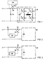
- An electrical machine M which can be operated in all quadrants of the speed-torque level is arranged in the bridge branch of a pulse converter UR with four controllable semiconductors H, freewheeling diodes D associated therewith and an upstream common intermediate circuit capacitor C. This arrangement is connected to a DC supply, not shown, via DC supply lines L + and L-.
- a protective diode DS which is polarized permeable during motor operation of the machine M is arranged in front of the pulse converter UR together with the intermediate circuit capacitor C, which is bridged by a controllable power semiconductor HS with the opposite direction of current flow (anti-parallel connection), so that Both a motor current and a generator current of the machine M can flow if the DC supply is faultless.
- the intermediate circuit capacitor C would discharge without the short-circuit protection via the short-circuit point between L + and L- and a machine short-circuit current could develop due to the then decreasing capacitor voltage via the freewheeling diodes D.
- the short-circuit protection has a quick-release monitoring device EW for the power semiconductor HS of the anti-parallel connection, which is connected in the area of the anti-parallel connection to the relevant DC supply line L + and detects a short circuit in the DC supply by monitoring the U CE voltage of the power semiconductor (transistor) HS and gives a blocking command to the power semiconductor HS in the event of a short-circuit in the direct current feed within microseconds before the short-circuit current can rise to a dangerous value. This prevents an appreciable discharge of the intermediate circuit capacitor C and thus a machine short-circuit current.
- the monitoring device EW can also be connected to a DC supply line via a current transformer W and connected to the power semiconductor HS, or the monitoring device EW can be galvanically connected to both DC supply lines according to FIG. 3.
- a diode Dp is provided between the direct current leads L + and L- in connection with the anti-parallel circuit HS, DS.
Abstract
In einer Gleichstromzuleitung (L+, L-) ist eine Antiparallelschaltung (DS, HS) vorgesehen, die in Schaltabhängigkeit von einer kurzschlußerfassenden Überwachungseinrichtung (EW) gebracht ist, so daß ein Zwischenkreiskondensator (C) des die Maschine (M) speisenden Pulsumrichters (UR) von der Kurzschlußstelle getrennt wird und der Zwischenkreiskondensator gegen die Kurzschlußstelle abgesperrt ist.An anti-parallel circuit (DS, HS) is provided in a direct current supply line (L +, L-), which is switched dependent on a short-circuit monitoring device (EW) so that an intermediate circuit capacitor (C) of the pulse converter (UR) feeding the machine (M) is disconnected from the short-circuit point and the intermediate circuit capacitor is blocked against the short-circuit point.
Description
Die Erfindung betrifft einen Kurzschlußschutz für eine motorisch sowie generatorisch betreibbare pulsumrichtergespeiste elektrische Maschine, d.h. eine Maschine, die in allen vier Quadranten der Drehzahl-Drehmoment-Ebene betriebsfähig ist und die bei einem Kurzschluß auf der Gleichstromeinspeisung von der äußeren Energieversorgung abgeschaltet wird. Bei Verwendung von auf Kurzschuß ansprechende Sicherungen ist ein zeitaufwendiger Austausch der Sicherungen notwendig, bei Verwendung von mechanischen Schaltmitteln mit nicht vernachlässigbaren Ansprechverzögerung kann der Kurzschlußstrom bis zum Unterbrechen der Energiezufuhr unzulässig hohe Werte erreichen.The invention relates to short-circuit protection for a motor-driven and generator-operated pulse converter-fed electrical machine, i.e. a machine which is operational in all four quadrants of the speed-torque level and which is switched off from the external power supply in the event of a short circuit on the direct current feed. When using fuses responding to short-circuit, a time-consuming replacement of the fuses is necessary; when using mechanical switching devices with a non-negligible response delay, the short-circuit current can reach inadmissibly high values until the power supply is interrupted.
Aufgabe der Erfindung ist es daher, mit schnell wirkenden, nicht einer Auswechselung unterliegenden Mitteln einen sicheren Kurzschlußschutz für eine obengenannte pulsumrichtergespeiste elektrische Maschine zu schaffen, wobei vorausgesetzt ist, daß der Pulsumrichter üblicherweise einen Zwischenkreiskondensator und Freilaufdioden zu den einzelnen steuerbaren Halbleitern des Pulsumrichters enthält.The object of the invention is therefore to provide a safe short-circuit protection for an above-mentioned pulse converter-fed electrical machine with fast-acting, not subject to exchange means, provided that the pulse converter usually contains an intermediate circuit capacitor and freewheeling diodes to the individual controllable semiconductors of the pulse converter.
Die Lösung der gestellten Aufgabe gelingt durch die kennzeichnenden Merkmale des Anspruchs 1. Zur Unterbindung von Schaltüberspannungen infolge schneller Stromänderungen in den Induktivitäten der Gleichstromzuleitungen ist eine zusätzliche Maßnahme nach Anspruch 2 vorgesehen.The problem is solved by the characterizing features of claim 1. An additional measure according to claim 2 is provided to prevent switching overvoltages due to rapid current changes in the inductances of the direct current feed lines.
Als schaltbare antiparallele Leistungshalbleiter können Transistoren, GTO oder ähnlich wirkende elektronische Schaltmittel dienen, die in Schaltabhängigkeit von einer elektronischen Überwachungseinrichtung gebracht sind, die z.B. eine UCE-Überwachung eines Transistors vornimmt. Die Überwachungseinrichtung ist mit mindestens einer der Gleichstromzuleitungen elektrisch verbunden, so daß sie einen einspeiseseitigen Kurzschluß erfassen kann.Transistors, GTOs or similarly acting electronic switching means can be used as switchable antiparallel power semiconductors which are brought into switching dependence by an electronic monitoring device which, for example, performs U CE monitoring of a transistor. The monitoring device is electrically connected to at least one of the direct current feed lines, so that it can detect a short circuit on the supply side.
Zur Unterbindung von Schaltüberspannungen ist vor der Antiparallelschaltung zwischen den beiden Gleichstromzuleitungen eine Zusatzdiode angeschlossen, über die im Normalfall kein Strom fließen kann.To prevent switching overvoltages, an additional diode is connected before the anti-parallel connection between the two direct current leads, through which no current can normally flow.
Einige vereinfachte Ausführungsbeispiele sind schematisch in der Zeichnung dargestellt und nachfolgend erläutert.Some simplified exemplary embodiments are shown schematically in the drawing and explained below.
Eine in allen Quadranten der Drehzahl-Drehmoment-Ebene betreibbare elektrische Maschine M ist im Brückenzweig eines Pulsumrichters UR mit vier steuerbaren Halbleitern H, diesen zugeordneten Freilaufdioden D sowie einem vorgeordneten gemeinsamen Zwischenkreiskondensator C angeordnet. Diese Anordnung ist über Gleichstromzuleitungen L+ und L- an eine nicht dargestellte Gleichstromeinspeisung angeschlossen.An electrical machine M which can be operated in all quadrants of the speed-torque level is arranged in the bridge branch of a pulse converter UR with four controllable semiconductors H, freewheeling diodes D associated therewith and an upstream common intermediate circuit capacitor C. This arrangement is connected to a DC supply, not shown, via DC supply lines L + and L-.
Im Zuge einer der Gleichstromzuleitungen (L+) ist gemäß Fig. 1 eine bei motorischem Betrieb der Maschine M stromdurchlässig gepolte Schutzdiode DS vor dem Pulsumrichter UR samt Zwischenkreiskondensator C angeordnet, die von einem steuerbaren Leistungshalbleiter HS mit entgegengesetzter Stromdurchlaßrichtung überbrückt ist (Antiparallelschaltung), so daß sowohl ein Motorstrom als auch ein Generatorstrom der Maschine M bei einwandfreier Gleichstromeinspeisung fließen kann.In the course of one of the direct current leads (L +), a protective diode DS which is polarized permeable during motor operation of the machine M is arranged in front of the pulse converter UR together with the intermediate circuit capacitor C, which is bridged by a controllable power semiconductor HS with the opposite direction of current flow (anti-parallel connection), so that Both a motor current and a generator current of the machine M can flow if the DC supply is faultless.
Bei Kurzschluß auf der Gleichstromeinspeisung vor der besagten Antiparallelschaltung würde sich ohne den Kurzschlußschutz der Zwischenkreiskondensator C über die Kurzschlußstelle zwischen L+ und L- entladen und wegen der sich dann abbauenden Kondensatorspannung über die Freilaufdioden D ein Maschinenkurzschlußstrom ausbilden können.In the event of a short circuit on the direct current feed before said anti-parallel connection, the intermediate circuit capacitor C would discharge without the short-circuit protection via the short-circuit point between L + and L- and a machine short-circuit current could develop due to the then decreasing capacitor voltage via the freewheeling diodes D.
Der Kurzschlußschutz weist hierzu eine schnellauslösende Überwachungseinrichtung EW für den Leistungshalbleiter HS der Antiparallelschaltung auf, der im Bereich der Antiparallelschaltung an die betreffende Gleichstromzuleitung L+ angeschlossen ist und einen Kurzschluß in der Gleichstromeinspeisung erkennt, indem sie die UCE-Spannung des Leistungshalbleiters (Transistors) HS überwacht und bei Kurzschluß in der Gleichstrom-Einspeisung innerhalb von Mikrosekunden einen Sperrbefehl an den Leistungshalbleiter HS gibt, bevor der Kurzschlußstrom auf einen gefährlichen Wert ansteigen kann. Dadurch wird eine nennenswerte Entladung des Zwischenkreiskondensators C und damit ein Maschinenkurzschlußstrom verhindert.For this purpose, the short-circuit protection has a quick-release monitoring device EW for the power semiconductor HS of the anti-parallel connection, which is connected in the area of the anti-parallel connection to the relevant DC supply line L + and detects a short circuit in the DC supply by monitoring the U CE voltage of the power semiconductor (transistor) HS and gives a blocking command to the power semiconductor HS in the event of a short-circuit in the direct current feed within microseconds before the short-circuit current can rise to a dangerous value. This prevents an appreciable discharge of the intermediate circuit capacitor C and thus a machine short-circuit current.
Die Überwachungseinrichtung EW kann gemäß Fig. 2 auch über einen Stromwandler W an eine Gleichstromzuleitung angeschlossen und mit dem Leistungshalbleiter HS verbunden sein oder es kann nach Fig. 3 die Überwachungseinrichtung EW an beide Gleichstromzuleitungen galvanisch angeschlossen sein.2, the monitoring device EW can also be connected to a DC supply line via a current transformer W and connected to the power semiconductor HS, or the monitoring device EW can be galvanically connected to both DC supply lines according to FIG. 3.
Zur Vermeidung von Schaltüberspannungen am Leistungshalbleiter HS infolge schneller Stromänderungen aufgrund der Leitungsinduktivitäten der Gleichstromeinspeisung ist zwischen den Gleichstromzuleitungen L+ und L- in Verbindung mit der Antiparallelschaltung HS,DS eine Diode Dp vorgesehen.In order to avoid switching overvoltages on the power semiconductor HS due to rapid current changes due to the line inductances of the direct current feed, a diode Dp is provided between the direct current leads L + and L- in connection with the anti-parallel circuit HS, DS.
Claims (2)
dadurch gekennzeichnet,
daß in einer Gleichstromzuleitung (L+/L-) eine Antiparallelschaltung aus einer nur den motorischen Maschinenstrom durchlassend gepolten Schutzdiode (DS) und einem nur den generatorischen Maschinenstrom durchlassenden steuerbaren Leistungshalbleiter (HS) angeordnet ist, der in Ausschalt-Abhängigkeit von einer einen Kurzschluß in der Gleichstromeinspeisung erfassenden schnellauslösenden Überwachungseinrichtung (EW) steht, so daß ein Zwischenkreiskondensator (C) des Pulsumrichters (UR) von der Kurzschlußstelle in der Gleichstromeinspeisung getrennt ist und die Spannung des Zwischenkreiskondensators (C) einen Maschinenkurzschlußstrom über die Freilaufdioden (D) des Umrichters (UR) unterbindet.1. Short-circuit protection for a pulse converter-fed electrical machine that can be operated in all quadrants of the speed-torque characteristic diagram,
characterized,
that in a direct current supply line (L + / L-) an anti-parallel circuit is arranged consisting of a protective diode (DS) which only allows the motor machine current to pass through and a controllable power semiconductor (HS) which only allows the generator's machine current to pass, which, depending on the switch-off, has a short circuit in the Fast-triggering monitoring device (EW) detecting direct current feed, so that an intermediate circuit capacitor (C) of the pulse converter (UR) is separated from the short circuit point in the direct current feed and the voltage of the intermediate circuit capacitor (C) a machine short-circuit current via the freewheeling diodes (D) of the converter (UR) prevents.
dadurch gekennzeichnet,
daß im Anschlußbereich der Antiparallelschaltung zwischen den beiden Gleichstromzuleitungen (L+,L-) eine Diode (Dp) angebracht ist.2. short-circuit protection according to claim 1,
characterized by
that a diode (Dp) is attached in the connection area of the anti-parallel connection between the two direct current leads (L +, L-).
Applications Claiming Priority (2)
| Application Number | Priority Date | Filing Date | Title |
|---|---|---|---|
| DE3809203 | 1988-03-18 | ||
| DE3809203 | 1988-03-18 |
Publications (2)
| Publication Number | Publication Date |
|---|---|
| EP0332974A1 true EP0332974A1 (en) | 1989-09-20 |
| EP0332974B1 EP0332974B1 (en) | 1992-10-14 |
Family
ID=6350135
Family Applications (1)
| Application Number | Title | Priority Date | Filing Date |
|---|---|---|---|
| EP89103920A Expired - Lifetime EP0332974B1 (en) | 1988-03-18 | 1989-03-06 | Short circuit protection for a pulse converter powered electric machine operated both motorically and generatingly |
Country Status (7)
| Country | Link |
|---|---|
| US (1) | US4890181A (en) |
| EP (1) | EP0332974B1 (en) |
| JP (1) | JP3040782B2 (en) |
| AU (1) | AU607847B2 (en) |
| BR (1) | BR8901230A (en) |
| CA (1) | CA1302482C (en) |
| DE (1) | DE58902444D1 (en) |
Cited By (1)
| Publication number | Priority date | Publication date | Assignee | Title |
|---|---|---|---|---|
| DE19736903A1 (en) * | 1997-08-25 | 1999-03-04 | Asea Brown Boveri | Converter with rectifier, inverter and intermediate circuits |
Families Citing this family (5)
| Publication number | Priority date | Publication date | Assignee | Title |
|---|---|---|---|---|
| US7516325B2 (en) * | 2001-04-06 | 2009-04-07 | Certicom Corp. | Device authentication in a PKI |
| JP2002330593A (en) * | 2001-05-07 | 2002-11-15 | Toshiba Corp | Electric power converter |
| US7031132B1 (en) | 2002-06-14 | 2006-04-18 | Mitchell Dennis A | Short circuit diagnostic tool |
| GB0221154D0 (en) * | 2002-09-12 | 2002-10-23 | Switched Reluctance Drives Ltd | A circuit for use with switched reluctance machines |
| CN101707471A (en) * | 2009-11-16 | 2010-05-12 | 孙宏斌 | Stepless speed regulation circuit of single-phase alternating-current motor |
Citations (1)
| Publication number | Priority date | Publication date | Assignee | Title |
|---|---|---|---|---|
| FR2577079A1 (en) * | 1985-01-31 | 1986-08-08 | Option | Auxiliary current source for chopped supply circuit |
Family Cites Families (4)
| Publication number | Priority date | Publication date | Assignee | Title |
|---|---|---|---|---|
| DE3037305C2 (en) * | 1980-10-02 | 1986-04-03 | Flowtec AG, Reinach, Basel | Arrangement for generating constant magnetic fields of alternating polarity for magnetic-inductive flow measurement |
| US4410935A (en) * | 1981-03-23 | 1983-10-18 | General Signal Corporation | Current overload protection for inverter of uninterruptible power supply system |
| JPS57208894A (en) * | 1981-06-16 | 1982-12-22 | Fanuc Ltd | Controlling system for induction motor |
| JPS58207882A (en) * | 1982-05-26 | 1983-12-03 | Fanuc Ltd | Regenerative energy processor for ac motor |
-
1989
- 1989-03-06 EP EP89103920A patent/EP0332974B1/en not_active Expired - Lifetime
- 1989-03-06 DE DE8989103920T patent/DE58902444D1/en not_active Expired - Lifetime
- 1989-03-08 US US07/320,394 patent/US4890181A/en not_active Expired - Lifetime
- 1989-03-15 JP JP1063409A patent/JP3040782B2/en not_active Expired - Lifetime
- 1989-03-16 CA CA000593971A patent/CA1302482C/en not_active Expired - Fee Related
- 1989-03-17 BR BR898901230A patent/BR8901230A/en not_active IP Right Cessation
- 1989-03-17 AU AU31453/89A patent/AU607847B2/en not_active Ceased
Patent Citations (1)
| Publication number | Priority date | Publication date | Assignee | Title |
|---|---|---|---|---|
| FR2577079A1 (en) * | 1985-01-31 | 1986-08-08 | Option | Auxiliary current source for chopped supply circuit |
Non-Patent Citations (1)
| Title |
|---|
| PATENT ABSTRACTS OF JAPAN vol. 6, no. 222 (E-140) 1100 06 November 1982, & JP-A-57 126284 (SANKEN DENKI K.K.) 05 August 1982, * |
Cited By (2)
| Publication number | Priority date | Publication date | Assignee | Title |
|---|---|---|---|---|
| DE19736903A1 (en) * | 1997-08-25 | 1999-03-04 | Asea Brown Boveri | Converter with rectifier, inverter and intermediate circuits |
| US6040988A (en) * | 1997-08-25 | 2000-03-21 | Asea Brown Boveri Ag | Converter with DC voltage intermediate circuit and method for operating such a converter |
Also Published As
| Publication number | Publication date |
|---|---|
| US4890181A (en) | 1989-12-26 |
| BR8901230A (en) | 1989-11-07 |
| AU607847B2 (en) | 1991-03-14 |
| EP0332974B1 (en) | 1992-10-14 |
| JPH01274622A (en) | 1989-11-02 |
| AU3145389A (en) | 1989-09-21 |
| JP3040782B2 (en) | 2000-05-15 |
| CA1302482C (en) | 1992-06-02 |
| DE58902444D1 (en) | 1992-11-19 |
Similar Documents
| Publication | Publication Date | Title |
|---|---|---|
| DE3036619C2 (en) | Circuit arrangement for short-circuit protection of transistors | |
| DE19702134A1 (en) | Protection circuit for high-performance switch components | |
| EP2100368A1 (en) | Semiconductor protective elements for controlling short-circuits at the dc end of voltage source converters | |
| WO2009043186A2 (en) | Arrangement for protecting inverters comprising an intermediate voltage circuit from a bridge short-circuit | |
| EP0332974B1 (en) | Short circuit protection for a pulse converter powered electric machine operated both motorically and generatingly | |
| DE19736904A1 (en) | Power converter circuitry | |
| DE2343912B2 (en) | Power supply device, in particular for a motor vehicle | |
| DE3032328A1 (en) | OVERCURRENT PROTECTION CIRCUIT | |
| DE69534981T2 (en) | ERROR DETECTOR FOR SELF-SUPPLIED VOLTAGE SOURCE POWER CONVERTER | |
| DE10149581B4 (en) | Semiconductor device | |
| AT409318B (en) | PROTECTIVE CIRCUIT FOR A NETWORKED THYRISTOR BRIDGE | |
| DE2801844C2 (en) | ||
| DE2632381B2 (en) | Inverter circuit | |
| EP1516420B1 (en) | Circuit arrangement with a voltage link converter | |
| DE3622787C2 (en) | ||
| EP0667986B1 (en) | Device for protecting an inverter | |
| DE2906556C2 (en) | Overcurrent protection arrangement in the event of incorrect summing of a thyristor inverter of a crossover converter | |
| DE4114617C1 (en) | Overcurrent protective circuitry for switchable semiconductors in bridge circuit - operates threshold value switch if measured actual valve of current exceeds max. valve to control separate control modules assigned to each semiconductor | |
| DE3311426A1 (en) | Overvoltage protection device for an electrical valve, having feedback of a protective triggering in the event of overvoltage | |
| DE1538376B2 (en) | CIRCUIT ARRANGEMENT FOR THE PROTECTION OF A CONSUMER | |
| DE3129910C2 (en) | Arrangement for reducing the overvoltage stress on the thyristors and switches of a direct converter | |
| DE3815471C2 (en) | Low-loss wiring on at least one valve that can be switched off | |
| DE3712572C1 (en) | Circuit arrangement for overvoltage protection and call current feed on a connection line for telecommunications, in particular telephone switching systems | |
| DE19503375C2 (en) | Control circuit for two transistors connected in series | |
| DE3707310A1 (en) | THYRISTOR COMMUTATION CIRCUIT |
Legal Events
| Date | Code | Title | Description |
|---|---|---|---|
| PUAI | Public reference made under article 153(3) epc to a published international application that has entered the european phase |
Free format text: ORIGINAL CODE: 0009012 |
|
| AK | Designated contracting states |
Kind code of ref document: A1 Designated state(s): CH DE FR GB IT LI NL SE |
|
| 17P | Request for examination filed |
Effective date: 19891010 |
|
| 17Q | First examination report despatched |
Effective date: 19920325 |
|
| GRAA | (expected) grant |
Free format text: ORIGINAL CODE: 0009210 |
|
| AK | Designated contracting states |
Kind code of ref document: B1 Designated state(s): CH DE FR GB IT LI NL SE |
|
| REF | Corresponds to: |
Ref document number: 58902444 Country of ref document: DE Date of ref document: 19921119 |
|
| ET | Fr: translation filed | ||
| ITF | It: translation for a ep patent filed |
Owner name: STUDIO JAUMANN |
|
| GBT | Gb: translation of ep patent filed (gb section 77(6)(a)/1977) |
Effective date: 19930107 |
|
| PLBE | No opposition filed within time limit |
Free format text: ORIGINAL CODE: 0009261 |
|
| STAA | Information on the status of an ep patent application or granted ep patent |
Free format text: STATUS: NO OPPOSITION FILED WITHIN TIME LIMIT |
|
| 26N | No opposition filed | ||
| EAL | Se: european patent in force in sweden |
Ref document number: 89103920.8 |
|
| PGFP | Annual fee paid to national office [announced via postgrant information from national office to epo] |
Ref country code: NL Payment date: 19950331 Year of fee payment: 7 |
|
| PG25 | Lapsed in a contracting state [announced via postgrant information from national office to epo] |
Ref country code: NL Effective date: 19961001 |
|
| NLV4 | Nl: lapsed or anulled due to non-payment of the annual fee |
Effective date: 19961001 |
|
| PGFP | Annual fee paid to national office [announced via postgrant information from national office to epo] |
Ref country code: CH Payment date: 19990709 Year of fee payment: 11 |
|
| PGFP | Annual fee paid to national office [announced via postgrant information from national office to epo] |
Ref country code: SE Payment date: 20000323 Year of fee payment: 12 |
|
| PG25 | Lapsed in a contracting state [announced via postgrant information from national office to epo] |
Ref country code: CH Free format text: LAPSE BECAUSE OF NON-PAYMENT OF DUE FEES Effective date: 20000331 Ref country code: LI Free format text: LAPSE BECAUSE OF NON-PAYMENT OF DUE FEES Effective date: 20000331 |
|
| REG | Reference to a national code |
Ref country code: CH Ref legal event code: PL |
|
| PG25 | Lapsed in a contracting state [announced via postgrant information from national office to epo] |
Ref country code: SE Free format text: LAPSE BECAUSE OF NON-PAYMENT OF DUE FEES Effective date: 20010307 |
|
| EUG | Se: european patent has lapsed |
Ref document number: 89103920.8 |
|
| REG | Reference to a national code |
Ref country code: GB Ref legal event code: IF02 |
|
| PGFP | Annual fee paid to national office [announced via postgrant information from national office to epo] |
Ref country code: IT Payment date: 20080326 Year of fee payment: 20 Ref country code: GB Payment date: 20080313 Year of fee payment: 20 |
|
| PGFP | Annual fee paid to national office [announced via postgrant information from national office to epo] |
Ref country code: FR Payment date: 20080317 Year of fee payment: 20 Ref country code: DE Payment date: 20080519 Year of fee payment: 20 |
|
| REG | Reference to a national code |
Ref country code: GB Ref legal event code: PE20 Expiry date: 20090305 |
|
| PG25 | Lapsed in a contracting state [announced via postgrant information from national office to epo] |
Ref country code: GB Free format text: LAPSE BECAUSE OF EXPIRATION OF PROTECTION Effective date: 20090305 |