EP0332959A2 - Stereoscopic display system - Google Patents
Stereoscopic display system Download PDFInfo
- Publication number
- EP0332959A2 EP0332959A2 EP19890103846 EP89103846A EP0332959A2 EP 0332959 A2 EP0332959 A2 EP 0332959A2 EP 19890103846 EP19890103846 EP 19890103846 EP 89103846 A EP89103846 A EP 89103846A EP 0332959 A2 EP0332959 A2 EP 0332959A2
- Authority
- EP
- European Patent Office
- Prior art keywords
- image
- viewer
- image areas
- images
- virtual
- Prior art date
- Legal status (The legal status is an assumption and is not a legal conclusion. Google has not performed a legal analysis and makes no representation as to the accuracy of the status listed.)
- Granted
Links
- 230000000694 effects Effects 0.000 abstract description 3
- 239000011159 matrix material Substances 0.000 description 2
- 230000003287 optical effect Effects 0.000 description 2
- 210000004556 brain Anatomy 0.000 description 1
- 239000002131 composite material Substances 0.000 description 1
- 230000006735 deficit Effects 0.000 description 1
- 239000006185 dispersion Substances 0.000 description 1
- 230000008030 elimination Effects 0.000 description 1
- 238000003379 elimination reaction Methods 0.000 description 1
- 230000006870 function Effects 0.000 description 1
- 238000003384 imaging method Methods 0.000 description 1
- 238000009434 installation Methods 0.000 description 1
- 230000003993 interaction Effects 0.000 description 1
- 238000012634 optical imaging Methods 0.000 description 1
- 230000008447 perception Effects 0.000 description 1
Images

Classifications
-
- G—PHYSICS
- G02—OPTICS
- G02B—OPTICAL ELEMENTS, SYSTEMS OR APPARATUS
- G02B30/00—Optical systems or apparatus for producing three-dimensional [3D] effects, e.g. stereoscopic images
- G02B30/20—Optical systems or apparatus for producing three-dimensional [3D] effects, e.g. stereoscopic images by providing first and second parallax images to an observer's left and right eyes
- G02B30/34—Stereoscopes providing a stereoscopic pair of separated images corresponding to parallactically displaced views of the same object, e.g. 3D slide viewers
Definitions
- the exit optics can contain a single converging lens. However, it can also consist of two converging lenses individually assigned to the image areas. Collective lenses are not only to be understood as simple, but also composite lenses with a collective lens character.
- the image areas can also be formed by a combined or two mutually independent light valve bodies, to which a light area located in front of the focal plane of the exit optics on the other side is assigned.
- the light valve body can preferably be an LCD matrix which is permeable to the positive image surface points. With the help of such a light valve body, a perception phenomenon occurs.
- the arrangement of the light valve body in or within the vicinity of the focal length of the exit optics (collimator optics) leads to the fact that the image formed or modeled with the aid of the light valve body or the two image contents of the Image areas seem to be a long distance away. The result of this is that the eyes of the viewer are accommadated from a great distance or infinitely, which means a relaxed state for the eye.
- the viewer receives the image of the luminous surface, which in turn is located at a relatively short distance.
- This real image is additionally superimposed by the real images of the two aperture elements with the above-described effect of deleting one virtual image by superimposing this image with the real image of one aperture element.
- the viewer perceives the stereoscopic information composed of the two image areas lying at a great or infinite distance.
- the image width can apparently be adjusted by changing the transverse dispersion in addition or alternatively to shifting the light valve body within the focal length of the exit optics.
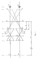
- FIGS. 1 and 2 serve to convey a stereoscopic image impression to the viewer. With both eyes A r and A l, the viewer is at the end of different beam paths.
- the beam paths start from different optical elements. These are two image areas 1r and 1l, which contain two images and whose superimposition in the brain of the viewer conveys the stereoscopic image impression.
- the aim is to ensure that the image information contained in the image area 1r only reaches the eye A r and the image information contained in the image area 1l only reaches the eye A l .
- This image information should in turn appear to lie in front of the viewer at a great distance in order to enable the viewer to look as accommodation-free as possible. This makes it possible to convey image information to the viewer when the viewer is in a motor vehicle and is looking at the traffic situation. In order to record the image information, it is then no longer necessary to look away from the traffic situation. Rather, the vehicle user receives the image information superimposed on the traffic situation.
- the real intermediate images 4r and 4l are created using a collimator lens 5 as virtual, i.e. image at an apparently greater distance for the viewer. This is achieved by the position of the intermediate images 4r and 4l being approximately at the focal length of the collimator lens 5.
- the position of the focal plane of the collimator lens 5 is indicated by the focal length f.
- the virtual image of the intermediate images 4r and 4l are located in a plane 8 and have an image width b that is significantly larger than the focal length f or the object width g.
- an aperture diaphragm consisting of two diaphragm elements 3r and 3l, which are also imaged with the aid of the collimator lens 5, is additionally arranged outside the focal length of the collimator lens 5 on the other side, based on the viewer.
- This image takes the form of a real image and is intended to take place in the plane determined by the viewer's eyes A r and A l .
- This position and image of the lens elements 3r and 3l should be chosen so that the diaphragm element 3r in the eye A l , the diaphragm element 3l in the eye A r is real.
- the eyes A r and A l two virtual images of the image areas 1r and 1l as well as a real image of an aperture element are superimposed.
- the real image of the screen member 3r indicated that the virtual image of the image surface 1r superimposed in the eye A l and is thus eliminated.
- the eye A r in which the real image of the diaphragm element 3l and the virtual image of the image area 1l overlap.
- the two eyes A r and A l each receive only the effective - virtual - image of the image areas 1r and 1l.
- the image information is generated with the aid of two image areas 1r 'and 1l' as a modulated image of a luminous area 9.
- the image areas 1r 'and 1l' are generated as a light valve with the aid of an LCD film or LCD matrix, which are suitable for the desired positive, i.e. brightly appearing pixels permeable to the negative, i.e. dark appearing pixels is switched opaque.
- the luminous surface 9 is designed as a pure diffuser. It is usually a fluorescent screen that is irradiated by a light source 10, or even as a luminous surface, e.g. is designed as an electroluminescent film.
- the arrangement of the image areas 1r 'and 1l' is approximately in the focal plane of the collimator lens 5. It follows that the distance setting of the eyes A r and A l is characterized by the - apparent - distance of the plane 4 ', in which the image areas 1r 'and 1l' are. Since the plane 4 'coincides approximately with the focal plane of the collimator lens 5, this plane 4' is apparently in the infinite or, given the appropriate position of the plane 4 ', somewhat outside the focal plane of the collimator lens 5 at a great finite distance.
- the desired elimination of through the image areas 1r 'and 1l' with certain image information in the eyes A l and A r of the viewer - due to the virtual image of the image areas 1r 'and 1l' - is carried out as in the embodiment of FIG. 1 by achieved a real image of aperture elements 3r and 3l in the desired eyes A l for the real image of the aperture element 3r and A r for the real image of the aperture element 3l.
- these real images of the aperture elements 3r and 3l are indicated as images in a plane 6 directly in front of the eyes A r and A l .
- this prevents the image information of the images contained in the two image areas from being crosstalked by the unwanted eye and thus gives the viewer an unobstructed, pure stereoscopic impression.
- the embodiment of Fig. 2 is characterized by a significantly reduced depth.
Landscapes
- Physics & Mathematics (AREA)
- General Physics & Mathematics (AREA)
- Optics & Photonics (AREA)
- Testing, Inspecting, Measuring Of Stereoscopic Televisions And Televisions (AREA)
Abstract
Description
Die Erfindung bezieht sich auf ein stereoskopisches Display-System zum Erzeugen einer dreidimensionalen Darstellung für einen Betrachter.The invention relates to a stereoscopic display system for generating a three-dimensional representation for an observer.
Unter dreidimensionalen Darstellungen sind solche zu verstehen, die der Betrachter als scheinbar dreidimensional wahrnimmt. Anwendungen derartiger Systeme finden sich bei Luft, Land oder Seefahrzeugen sowie deren Simulatoren, ferner bei computergestützen Anzeigesystemen sowie in Spielen und in Werbung. Ein besonders wichtiger Anwendungsfall liegt bei Kraftfahrzeugen vor. Dabei dienen derartige Systeme dazu Informationen in variablem Abstand vor dem Kraftfahrzeug darzustellen.Three-dimensional representations are those that the viewer perceives as seemingly three-dimensional. Such systems are used in air, land or sea vehicles and their simulators, furthermore in computer-aided display systems as well as in games and in advertising. A particularly important application is in motor vehicles. Such systems are used to present information at variable distances in front of the motor vehicle.
Bei derartigen Darstellungen besteht ein grundlegendes Problem. Da es häufig gewünscht ist, die Darstellung (scheinbar), d.h. als virtuelles Bild, in möglichst großer Entfernung dazustellen, ergibt sich am Ort des Betrachters in der Regel eine Überlagerung der beiden virtuellen Bilder der Displays. Diese Überlagerung findet in jedem Auge statt und führt dazu, daß der stereoskopische Eindruck verringert oder aufgehoben wird. Diese Aussage gilt zumindest dann, wenn keine besonderen Maßnahmen ergriffen werden, die beiden virtuellen Bilder der Bildflächen auseinander zu halten. Derartige Vorkehrungen sind jedoch in der Regel besonders aufwendig und gerade für den Anwendungsfall bei Kraftfahrzeugen aufgrund der räumlich beengten Einbauverhältnisse nur schwer oder überhaupt nicht mit vertretbarem Aufwand realisierbar. Die Aussage, das virtuelle Bild in großer Entfernung zu erzeugen, bedeutet für Kraftfahrzeuge beispielsweise eine Entfernung von einigen Metern vor dem Kraftfahrzeug und reicht bis zu einer Entfernung, die beispielsweise durch den jeweiligen Sicherheitsabstand definiert ist. Dieser ist wiederum abhängig vom Quadrat der Fahrzeuggeschwindigkeit.There is a fundamental problem with such representations. Since it is often desired to present the display (apparently), ie as a virtual image, as far away as possible, there is usually an overlay of the two virtual images of the displays at the location of the viewer. This superposition takes place in each eye and leads to the stereoscopic impression being reduced or eliminated. This statement applies at least if no special measures are taken to keep the two virtual images of the image areas apart. Such precautions are usually particularly complex and especially for the application in the case of motor vehicles, because of the space-constrained installation conditions, it is difficult or impossible to implement at all with reasonable effort. For motor vehicles, the statement that the virtual image is generated at a great distance means, for example, a distance of a few meters in front of the motor vehicle and extends to a distance that is defined, for example, by the respective safety distance. This in turn depends on the square of the vehicle speed.
Es ist daher Aufgabe der Erfindung, ein stereoskopisches Display-System zu schaffen, das mit geringem konstruktiven Aufwand den stereoskopischen Eindruck möglichst uneingeschränkt zur Wirkung kommen läßt.It is therefore an object of the invention to provide a stereoscopic display system which allows the stereoscopic impression to come into effect as freely as possible with little design effort.
Die Erfindung löst diese Aufgabe durch die Kombination der Merkmale, die im kennzeichnenden Teil des Patentanspruchs 1 angegeben ist.The invention solves this problem by combining the features specified in the characterizing part of
Grundlegend für die Erfindung ist die Überlagerung des reellen Bildes eines der beiden Blendenelemente mit gerade dem virtuellen Bild der Bildfläche, das nicht in das Auge des Betrachters gelangen soll. Das reelle Bild des Blendenelements löscht sozusagen dieses "störende" virtuelle Bild aus. In das Auge des Betrachters gelangt somit lediglich das virtuelle Bild der gewünschten Bildfläche. Da für die beiden Augen des Betrachters jeweils verschiedene virtuelle Bilder der Bildflächen aufgehoben werden, sind die beiden wirksamen virtuellen Bilder ebenfalls voneinander verschieden. Damit aber erscheint dem Betrachter die Darstellung uneingeschränkt dreidimensional, da er in beiden Augen verschiedene (virtuelle) Bilder von verschiedenen Bildflächen empfängt. Wie an sich bekannt, kann der plastische Eindruck durch Querdisparation der beiden Bildflächen verändert werden. Dabei kann die tatsächliche Bildweite konstant bleiben. Die Bildweite sollte jedoch mindestens 3 m betragen, da ab dieser Entfernung das Auge auf Unendlich akkommodiert ist.Fundamental to the invention is the superimposition of the real image of one of the two diaphragm elements with just the virtual image of the image area, which should not get into the eye of the beholder. The real image of the aperture element erases this "disturbing" virtual image, so to speak. Only the virtual image of the desired image area thus gets into the eye of the beholder. Since different virtual images of the image areas are each canceled for the two eyes of the viewer, the two effective virtual images are also different from one another. However, this means that the viewer appears three-dimensional without restriction, since he receives different (virtual) images from different image areas in both eyes. As is known per se, the three-dimensional impression can be achieved by cross-disparity between the two picture areas to be changed. The actual image width can remain constant. However, the image width should be at least 3 m, since from this distance the eye is accommodated for infinity.
Die Realisierung der Erfindung ist auf verschiedene Weise möglich. So kann die Austrittsoptik eine einzige Sammellinse enthalten. Sie kann aber auch aus zwei den Bildflächen individuell zugeordneten Sammellinsen bestehen. Unter Sammellinsen sind nicht nur einfache, sondern auch zusammengesetzte Linsen mit Sammellinsencharakter zu verstehen.The implementation of the invention is possible in various ways. So the exit optics can contain a single converging lens. However, it can also consist of two converging lenses individually assigned to the image areas. Collective lenses are not only to be understood as simple, but also composite lenses with a collective lens character.
Die Bildflächen ihrerseits können auf verschiedene Weise dargestellt sein. Es kann sich einerseits um reelle Zwischenbilder von Bildern (Gegenständen) handeln, die vor der - bezogen auf den Betrachter - jenseitigen Brennebene der Austrittsoptik liegen und mittels einer Vorschaltoptik abgebildet sind. Die Vorschaltoptik ihrerseits kann wiederum aus einer oder zwei individuell den beiden Bildern zugeordneten Linsen bzw. Linsensystemen bestehen.The image areas themselves can be displayed in different ways. On the one hand, they can be real intermediate images of images (objects) that lie in front of the focal plane of the exit optics - based on the viewer - and are imaged by means of a ballast optics. The ballast optics in turn can consist of one or two lenses or lens systems individually assigned to the two images.
Andererseits können die Bildflächen auch durch einen kombinierten oder zwei voneinander unabhängige Lichtventilkörper gebildet sein, dem bzw. denen eine vor der jenseitigen Brennebene der Austrittsoptik gelegene Leuchtfläche zugeordnet ist. Der Lichtventilkörper kann vorzugsweise eine LCD-Matrix sein, die für die positiven Bildflächenpunkte durchlässig ist. Mit Hilfe eines derartigen Lichtventilkörpers tritt ein Wahrnehmungsphänomen auf. Die Anordnung des Lichtventilkörpers in oder innerhalb in der Nähe der Brennweite der Austrittsoptik (Kollimatoroptik) führt dazu, daß das mit Hilfe des Lichtventilkörpers gebildete bzw. modellierte Bild bzw. die beiden Bildinhalte der Bildflächen scheinbar in großer Entfernung liegen. Die Folge davon ist, daß die Augen des Betrachters auf große Entfernung bzw. Unendlich akkommudiert sind, was für das Auge einen entspannten Zustand bedeutet.On the other hand, the image areas can also be formed by a combined or two mutually independent light valve bodies, to which a light area located in front of the focal plane of the exit optics on the other side is assigned. The light valve body can preferably be an LCD matrix which is permeable to the positive image surface points. With the help of such a light valve body, a perception phenomenon occurs. The arrangement of the light valve body in or within the vicinity of the focal length of the exit optics (collimator optics) leads to the fact that the image formed or modeled with the aid of the light valve body or the two image contents of the Image areas seem to be a long distance away. The result of this is that the eyes of the viewer are accommadated from a great distance or infinitely, which means a relaxed state for the eye.
Andererseits empfängt der Betrachter aber das Bild der Leuchtfläche, das wiederum in relativ geringer Entfernung liegt. Dieses reelle Bild wird zusätzlich überlagert von den reellen Bildern der beiden Blendenelemente mit dem obenbeschriebenen Effekt der Auslöschung je eines virtuellen Bildes durch die Überlagerung dieses Bildes mit dem reellen Bild je eines Blendenelements. Im Ergebnis führt dies dazu, daß der Betrachter die stereoskopische, aus den beiden Bildflächen zusammengesetzte Information in großer bzw. unendlicher Entfernung liegend wahrnimmt. Die Bildweite kann scheinbar durch verändern der Querdisparation ergänzend oder alternativ zum Verschieben des Lichtventilkörpers innerhalb der Brennweite der Austrittsoptik eingestellt werden.On the other hand, the viewer receives the image of the luminous surface, which in turn is located at a relatively short distance. This real image is additionally superimposed by the real images of the two aperture elements with the above-described effect of deleting one virtual image by superimposing this image with the real image of one aperture element. As a result, the viewer perceives the stereoscopic information composed of the two image areas lying at a great or infinite distance. The image width can apparently be adjusted by changing the transverse dispersion in addition or alternatively to shifting the light valve body within the focal length of the exit optics.
Eine konstruktive Vereinfachung ergibt sich für das zuletzt beschriebene System bei einstückiger Gestaltung der Leuchtfläche und der Blendenelemente.A constructional simplification results for the system described last with one-piece design of the luminous surface and the panel elements.
Der Vorteil der zuletzt beschriebenen zweiten Ausführungsform des Systems (mit Lichtventilkörpern) gegenüber dem ersten Ausführungsbeispiel liegt in der deutlich verringerten Bautiefe, die im wesentlichen lediglich durch die jenseitige Brennweite der Austrittsoptik und den Abstand des Leuchtkörpers von dieser Brennweite bestimmt ist. Dieser Abstand kann relativ gering gehalten werden und ermöglicht es, die aufgeführten optischen Elemente (Blendenelemente, Leuchtkörper und Austrittsoptik) innerhalb des Armaturenbretts eines Kraftfahrzeugs unterzubringen.The advantage of the last described second embodiment of the system (with light valve bodies) compared to the first embodiment lies in the significantly reduced overall depth, which is essentially only determined by the focal length of the exit optics on the other side and the distance of the luminous element from this focal length. This distance can be kept relatively short and makes it possible to accommodate the listed optical elements (diaphragm elements, luminous elements and exit optics) within the dashboard of a motor vehicle.
In der Zeichnung sind Ausführungsbeispiele der Erfindung dargestellt. Es zeigt
- Fig. 1 schematisch den Aufbau eines ersten Ausführungsbeispiels und
- Fig. 2 schematisch den Aufbau eines zweiten Ausführungsbeispiels der Erfindung.
- Fig. 1 shows schematically the structure of a first embodiment and
- Fig. 2 shows schematically the structure of a second embodiment of the invention.
Die Ausführungsbeispiele von Fig. 1 und 2 dienen dazu, dem Betrachter einen stereoskopischen Bildeindruck zu vermitteln. Der Betrachter befindet sich mit seinen beiden Augen Ar und Al am Ende von verschiedenen Strahlengängen.The exemplary embodiments of FIGS. 1 and 2 serve to convey a stereoscopic image impression to the viewer. With both eyes A r and A l, the viewer is at the end of different beam paths.
Bei Fig. 1 gehen die Strahlengänge von verschiedenen optischen Elementen aus. Dabei handelt es sich um zwei Bildflächen 1r und 1l, die zwei Bilder enthalten und deren Überlagerung im Gehirn des Betrachters den stereoskopischen Bildeindruck vermittelt. Dabei soll erreicht werden, daß die in der Bildfläche 1r enthaltene Bildinformation nur in das Auge Ar und die Bildinformation der Bildfläche 1l nur in das Auge Al gelangt. Diese Bildinformation soll ihrerseits in großer Entfernung vor dem Betrachter liegend erscheinen, um diesem eine möglichst akkommodationsfreie Betrachtung zu ermöglichen. Dadurch wird es möglich, eine Bildinformation dem Betrachter zu vermitteln, wenn dieser sich in einem Kraftfahrzeug befindet und seinen Blick auf das Verkehrsgeschehen richtet. Zum Aufnehmen der Bildinformation ist es dann nicht mehr erforderlich, den Blick vom Verkehrsgeschehen abzuwenden. Vielmehr erhält der Fahrzeugbenutzer die Bildinformation in Überlagerung mit dem Verkehrgeschehen.In Fig. 1, the beam paths start from different optical elements. These are two
Die Darstellung der Bildinformation in relativ großer Entfernung vor dem Fahrzeugbenutzer wird erreicht durch eine virtuelle Abbildung der in den Bildflächen 1r und 1l enthaltenen Bildinformation mit Hilfe einer Austrittsoptik, die aus zwei Sammellinsen 2r und 2l besteht. Diese erzeugen ein reelles Zwischenbild 4r und 4l, das lediglich seitenverkehrt ist. Voraussetzung hierfür ist, daß sich die Bildflächen 1r und 1l außerhalb der - bezüglich des Betrachters - jenseitigen Brennweite der Sammellinsen 2r und 2l befindet.The display of the image information at a relatively large distance in front of the vehicle user is achieved by virtual imaging of the image information contained in the
Die reellen Zwischenbilder 4r und 4l werden mit Hilfe einer Kollimatorlinse 5 als virtuelles, d.h. in einer scheinbaren größeren Entfernung liegendes Bild für den Betrachter abgebildet. Dies wird erreicht, in dem die Lage der Zwischenbilder 4r und 4l etwa in der Brennweite der Kollimatorlinse 5 gelegt sind. Die Lage der Brennebene der Kollimatorlinse 5 ist durch die Brennweite f angedeutet. Das virtuelle Bild der Zwischenbilder 4r und 4l befinden sich in einer Ebene 8 und besitzt eine Bildweite b, die deutlich größer als die Brennweite f bzw. die Gegenstandsweite g ist.The real intermediate images 4r and 4l are created using a
Das Problem einer derartigen stereoskopischen virtuellen Abbildung besteht darin, daß die Zwischenbilder 4r und 4l und damit die Bildflächen 1r und 1l nicht nur in den Augen Ar und Al der "richtigen" Seite - d.h., das Bild 4r nur im Auge Ar bzw. das Bild 4l im Auge Al - abgebildet werden, sondern aufgrund der Eigenschaften der virtuellen Abbildung auch in den jeweils anderen Augen (Übersprechen). Damit aber käme es in beiden Augen zu einer Überlagerung der beiden virtuellen Bilder der Bildflächen 1r und 1l und damit zu einer Beeinträchtigung bzw. Aufhebung des gewünschten stereoskopischen Bildeindrucks.The problem with such a stereoscopic virtual image is that the intermediate images 4r and 4l and thus the
Um dies zu vermeiden, ist zusätzlich außerhalb der - bezogen auf den Betrachter - jenseitigen Brennweite der Kollimatorlinse 5 eine aus zwei Blendenelementen 3r und 3l bestehende Aperturblende in einer Ebene 3 angeordnet, die ebenfalls mit Hilfe der Kollimatorlinse 5 abgebildet werden. Diese Abbildung erfolgt in Form eines reellen Bildes und soll in der durch die Augen Ar und Al des Betrachters bestimmten Ebene erfolgen. Dies wird durch eine entsprechende Wahl der Lage der Ebene 3 inbezug auf die optischen Abbildungseigenschaften der Kollimatorlinsen 5 erreicht. Diese Lage und Abbildung der Linsenelemente 3r und 3l soll dabei so gewählt sein, daß das Blendenelement 3r im Auge Al, das Blendenelement 3l im Auge Ar reell abgebildet wird.In order to avoid this, an aperture diaphragm consisting of two
In den Augen Ar und Al kommt es nun jeweils zur Überlagerung zweier virtueller Bilder der Bildflächen 1r und 1l sowie eines reellen Bildes eines Blendenelements. Dabei sorgt, wie durch den von den Blendenelementen 3r und 3l ausgehenden Strahlengang angedeutet das reelle Bild des Blendenelements 3r dafür, daß das virtuelle Bild der Bildfläche 1r im Auge Al überlagert und damit eliminiert wird. Dasselbe gilt für das Auge Ar in dem es zu einer Überlagerung des reellen Bildes des Blendenelements 3l und des virtuellen Bildes der Bildfläche 1l kommt. Somit empfangen die beiden Augen Ar und Al jeweils nur das wirksame - virtuelle - Bild der Bildflächen 1r bzw. 1l. Das Übersprechen der unerwünschten Bildinformation der Bildfläche 1r für das Auge Al und der Bildfläche 1l für das Auge Ar wird damit ausgeschlossen. Damit aber ist der stereoskopische Eindruck, der durch die beiden Bildflächen 1r und 1l hervorgerufen wird und durch Überlagerung der mit den Augen Ar und Al aufgenommenen - virtuellen - Bilder der Bildflächen 1r und 1l hervorgerufen wird, vollständig gegeben. Er läßt sich durch entsprechende seitliche Disparation der Bildflächen 1r und 1l im gewünschten Maße einstellen.In the eyes A r and A l , two virtual images of the
Beim Ausführungsbeispiel von Fig. 2 sind Teile gleicher Funktion mit gleichen Bezugszeichen wie in Fig. 1 bezeichnet. Im Unterschied zu Fig. 1 wird die Bildinformation mit Hilfe von zwei Bildflächen 1r′ und 1l′ als moduliertes Bild einer Leuchtfläche 9 erzeugt. Dabei sind die Bildflächen 1r′ und 1l′ als Lichtventil mit Hilfe einer LCD-Folie bzw. LCD-Matrix erzeugt, die für die gewünschten positiven, d.h. hell erscheinenden Bildpunkte durchlässig für die negativen, d.h. dunkel erscheinenden Bildpunkte lichtundurchlässig geschaltet ist. Die Leuchtfläche 9 ist als reiner Diffusor ausgebildet. Dabei handelt es sich in der Regel um einen Leuchtschirm, der durch eine Lichtquelle 10 bestrahlt ist, oder selbst als Leuchtfläche, z.B. als Elektrolumineszenzfolie ausgebildet ist.In the exemplary embodiment in FIG. 2, parts of the same function are designated with the same reference symbols as in FIG. 1. In contrast to Fig. 1, the image information is generated with the aid of two
Die Anordnung der Bildflächen 1r′ und 1l′ ist etwa in der Brennebene der Kollimatorlinse 5. Daraus ergibt sich, daß die Entfernungseinstellung der Augen Ar und Al durch die - scheinbare - Entfernung der Ebene 4′ geprägt ist, in der sich die Bildflächen 1r′ und 1l′ befinden. Da die Ebene 4′ in etwa mit der Brennebene der Kollimatorlinse 5 zusammenfällt, liegt diese Ebene 4′ scheinbar im unendlichen bzw. bei entsprechender Lage der Ebene 4′ etwas außerhalb der Brennebene der Kollimatorlinse 5 in großer endlicher Entfernung.The arrangement of the
Mit dieser durch die scheinbare sehr große Entfernung der Bildflächen 1r′ und 1l′ geprägten Einstellung der Augen Ar und Al, d.h. praktisch akkommodationsfreien Einstellung dieser Augen, wird eine Bildinformation wahrgenommen, die durch das Zusammenspiel der Bildflächen 1r′ und 1l′ und des Leuchtschirms 9 hervorgerufen wird. Der Leuchtschirm 9 befindet sich wiederum zwar außerhalb der jenseitigen Brennebene der Kollimatorlinse 5, jedoch in relativ kurzem Abstand hinter dieser Brennebene.With this setting of the eyes A r and A l , which is characterized by the seemingly very large distance of the
Das gewünschte Eliminieren der durch die Bildflächen 1r′ bzw. 1l′ mit bestimmten Bildinformationen in den Augen Al bzw. Ar des Betrachters - bedingt durch die virtuelle Abbildung der Bildflächen 1r′ und 1l′ - wird wie beim Ausführungsbeispiel von Fig. 1 durch eine reelle Abbildung von Blendenelementen 3r und 3l in den gewünschten Augen Al für das reelle Bild des Blendenelements 3r und Ar für das reelle Bild des Blendenelements 3l erreicht. Diese reellen Abbilder der Blendenelemente 3r und 3l sind wie in Fig. 1 als Bilder in einer Ebene 6 unmittelbar vor den Augen Ar und Al angedeutet.The desired elimination of through the
Damit wird auch beim Ausführungsbeispiel von Fig. 2 ein Übersprechen der Bildinformation der in den beiden Bildflächen enthaltenen Bilder für das nicht gewünschte Auge verhindert und damit ein unbehindeter, reiner stereoskopischer Eindruck dem Betrachter vermittelt. Gegenüber Fig. 1 zeichnet sich das Ausführungsbeispiel von Fig. 2 durch eine deutlich verringerte Bautiefe aus.In the exemplary embodiment of FIG. 2, this prevents the image information of the images contained in the two image areas from being crosstalked by the unwanted eye and thus gives the viewer an unobstructed, pure stereoscopic impression. Compared to Fig. 1, the embodiment of Fig. 2 is characterized by a significantly reduced depth.
Bei beiden Ausführungsbeispielen kann es sich bei den Kollimatorlinsen 5 um eine einzige oder um zwei Linsen handeln. Im letzteren Fall ergibt sich insofern ein Vorteil, als kürzere Brennweiten derartiger Linsen und damit eine geringere Baugröße möglich ist. Dadurch werden auch Korrekturen von Abbildungs- oder Linsenfehler leichter möglich.In both exemplary embodiments, the
Wie in Fig. 2 dargestellt, können zur Vereinheitlichung der konstruktiven Ausführung die Blendenelemente 3r und 3l einstückig mit dem Leuchtschirm 9 sein.As shown in Fig. 2, the
Claims (6)
- eine Austrittsoptik
- zwei Bildflächen, die in oder innerhalb in der Nähe der jenseitigen Brennweite der Austrittsoptik liegen und
- jeder Bildfläche zugeordnete Blendenelemente, die außerhalb der jenseitigen Brennebene der Austrittsoptik liegen und durch diese als reelle Bilder am Ort des Betrachters abgebildet sind,
- wobei für jedes Auge des Betrachters eines der beiden virtuellen Bilder der Bildflächen mit dem reellen Bild des diesen jeweils nicht zugeordneten Blendenelements überlagert ist.1. Stereoscopic display system for generating a three-dimensional representation for a viewer, characterized by the combination of the following features
- an exit optic
- Two image areas, which are in or within near the focal length of the exit optics and
- aperture elements assigned to each image area, which lie outside the focal plane of the exit optics on the other side and are represented by these as real images at the location of the viewer,
- wherein for each eye of the viewer one of the two virtual images of the image areas is overlaid with the real image of the aperture element not assigned to them.
Applications Claiming Priority (2)
| Application Number | Priority Date | Filing Date | Title |
|---|---|---|---|
| DE3808988A DE3808988A1 (en) | 1988-03-17 | 1988-03-17 | STEREOSCOPIC DISPLAY SYSTEM |
| DE3808988 | 1988-03-17 |
Publications (3)
| Publication Number | Publication Date |
|---|---|
| EP0332959A2 true EP0332959A2 (en) | 1989-09-20 |
| EP0332959A3 EP0332959A3 (en) | 1990-12-27 |
| EP0332959B1 EP0332959B1 (en) | 1994-06-08 |
Family
ID=6350008
Family Applications (1)
| Application Number | Title | Priority Date | Filing Date |
|---|---|---|---|
| EP89103846A Expired - Lifetime EP0332959B1 (en) | 1988-03-17 | 1989-03-04 | Stereoscopic display system |
Country Status (2)
| Country | Link |
|---|---|
| EP (1) | EP0332959B1 (en) |
| DE (2) | DE3808988A1 (en) |
Cited By (2)
| Publication number | Priority date | Publication date | Assignee | Title |
|---|---|---|---|---|
| WO1995014952A1 (en) * | 1993-11-23 | 1995-06-01 | Liquid Vision Limited | Stereoscopic imaging arrangement and viewing arrangement |
| EP0729054A1 (en) * | 1995-02-25 | 1996-08-28 | Lüder, Ernst, Prof. Dr.-Ing. habil. | Device and method for autostereoscopically displaying three-dimensional structures |
Families Citing this family (1)
| Publication number | Priority date | Publication date | Assignee | Title |
|---|---|---|---|---|
| DE102005046756B4 (en) * | 2005-09-29 | 2017-10-26 | Volkswagen Ag | Method and device for displaying information of an automatic distance control |
Citations (3)
| Publication number | Priority date | Publication date | Assignee | Title |
|---|---|---|---|---|
| FR1407269A (en) * | 1964-06-20 | 1965-07-30 | Optical device for relief vision | |
| EP0185419A2 (en) * | 1984-12-17 | 1986-06-25 | Philips Patentverwaltung GmbH | Imaging device |
| WO1988008146A1 (en) * | 1987-04-10 | 1988-10-20 | Holtronic Gesellschaft Für Holographie Und Elektro | Stereoscopic display system |
Family Cites Families (2)
| Publication number | Priority date | Publication date | Assignee | Title |
|---|---|---|---|---|
| US2492270A (en) * | 1946-04-15 | 1949-12-27 | Cornalba Tulio Humbert Antonio | Stereo-optical system |
| US3737567A (en) * | 1971-10-25 | 1973-06-05 | S Kratomi | Stereoscopic apparatus having liquid crystal filter viewer |
-
1988
- 1988-03-17 DE DE3808988A patent/DE3808988A1/en not_active Withdrawn
-
1989
- 1989-03-04 DE DE58907807T patent/DE58907807D1/en not_active Expired - Fee Related
- 1989-03-04 EP EP89103846A patent/EP0332959B1/en not_active Expired - Lifetime
Patent Citations (3)
| Publication number | Priority date | Publication date | Assignee | Title |
|---|---|---|---|---|
| FR1407269A (en) * | 1964-06-20 | 1965-07-30 | Optical device for relief vision | |
| EP0185419A2 (en) * | 1984-12-17 | 1986-06-25 | Philips Patentverwaltung GmbH | Imaging device |
| WO1988008146A1 (en) * | 1987-04-10 | 1988-10-20 | Holtronic Gesellschaft Für Holographie Und Elektro | Stereoscopic display system |
Cited By (6)
| Publication number | Priority date | Publication date | Assignee | Title |
|---|---|---|---|---|
| WO1995014952A1 (en) * | 1993-11-23 | 1995-06-01 | Liquid Vision Limited | Stereoscopic imaging arrangement and viewing arrangement |
| GB2298989A (en) * | 1993-11-23 | 1996-09-18 | Liquid Vision Limited | Stereoscopic imaging arrangement and viewing arrangement |
| GB2298989B (en) * | 1993-11-23 | 1997-07-23 | Liquid Vision Limited | Stereoscopic imaging arrangement and viewing arrangement |
| US5914810A (en) * | 1993-11-23 | 1999-06-22 | Watts; Jonathan Robert | Stereoscopic imaging arrangement and viewing arrangement |
| EP0729054A1 (en) * | 1995-02-25 | 1996-08-28 | Lüder, Ernst, Prof. Dr.-Ing. habil. | Device and method for autostereoscopically displaying three-dimensional structures |
| US5777787A (en) * | 1995-02-25 | 1998-07-07 | Ernst Lueder | Apparatus and process for autostereoscopic viewing of a three-dimensional structure |
Also Published As
| Publication number | Publication date |
|---|---|
| EP0332959B1 (en) | 1994-06-08 |
| EP0332959A3 (en) | 1990-12-27 |
| DE58907807D1 (en) | 1994-07-14 |
| DE3808988A1 (en) | 1989-10-05 |
Similar Documents
| Publication | Publication Date | Title |
|---|---|---|
| DE68922864T2 (en) | THREE-DIMENSIONAL DISPLAY DEVICE. | |
| EP0909517B1 (en) | Method and facility for light-beam projection of images on a screen | |
| DE19930710C2 (en) | Image display system and method for vehicles | |
| DE60318871T2 (en) | DISPLAY SYSTEM FOR DISPLAYING IMAGES IN A VEHICLE | |
| DE69421186T2 (en) | STEREO-OPTICAL IMAGE DISPLAY SYSTEM WITH IMPROVED RESOLUTION | |
| EP1600007B1 (en) | Stereoscopic display arrangement | |
| DE19540108C2 (en) | Device for displaying a first image in a second image visible through a transparent pane | |
| EP0871913B1 (en) | Microscope | |
| EP2357831B1 (en) | Method and system for light-beam projection of images on a screen | |
| WO1999066356A1 (en) | Three-dimensional representation system | |
| DE102014008153A1 (en) | Display device and method for augmented representation of a picture object | |
| DE102014001710A1 (en) | Device for augmented representation of virtual image object in real environment of vehicle, e.g. head-up-display, reflects partial images by disc, so that virtual image object is output as virtual depth image in real environment | |
| WO2003102666A1 (en) | Autostereoscopic display for motor vehicles | |
| DE102015206001A1 (en) | Autostereoscopic head-up display for a vehicle and method for generating an autostereoscopic image by means of a head-up display for a vehicle | |
| DE102009054231A1 (en) | Head-up-display for information indication in motor vehicle, comprises indicating unit, which has display unit, in which lighting points are produced | |
| EP0937274B1 (en) | Stereo hologram display (holdisp) | |
| DE69610206T2 (en) | STEREOSCOPIC DISPLAY DEVICE | |
| DE102016113518A1 (en) | Devices for data input | |
| DE10302387A1 (en) | Head up display for motor vehicle divides display image into strips to provide reduction of parallax | |
| DE102016111119A1 (en) | Laser projection device and method for generating virtual images | |
| EP2122415B1 (en) | Autostereoscopic image display appliance for producing a floating real stereo image | |
| EP0332959B1 (en) | Stereoscopic display system | |
| WO2019015895A1 (en) | Projection display device with representation in multiple display planes | |
| DE102019218627A1 (en) | Augmented reality head-up display | |
| EP1544662B1 (en) | Observation system and observation process |
Legal Events
| Date | Code | Title | Description |
|---|---|---|---|
| PUAI | Public reference made under article 153(3) epc to a published international application that has entered the european phase |
Free format text: ORIGINAL CODE: 0009012 |
|
| AK | Designated contracting states |
Kind code of ref document: A2 Designated state(s): DE ES FR GB IT SE |
|
| PUAL | Search report despatched |
Free format text: ORIGINAL CODE: 0009013 |
|
| AK | Designated contracting states |
Kind code of ref document: A3 Designated state(s): DE ES FR GB IT SE |
|
| 17P | Request for examination filed |
Effective date: 19901122 |
|
| 17Q | First examination report despatched |
Effective date: 19921209 |
|
| RAP3 | Party data changed (applicant data changed or rights of an application transferred) |
Owner name: BAYERISCHE MOTOREN WERKE AKTIENGESELLSCHAFT |
|
| RAP1 | Party data changed (applicant data changed or rights of an application transferred) |
Owner name: BAYERISCHE MOTOREN WERKE AKTIENGESELLSCHAFT |
|
| GRAA | (expected) grant |
Free format text: ORIGINAL CODE: 0009210 |
|
| AK | Designated contracting states |
Kind code of ref document: B1 Designated state(s): DE ES FR GB IT SE |
|
| PG25 | Lapsed in a contracting state [announced via postgrant information from national office to epo] |
Ref country code: ES Free format text: THE PATENT HAS BEEN ANNULLED BY A DECISION OF A NATIONAL AUTHORITY Effective date: 19940608 |
|
| ET | Fr: translation filed | ||
| REF | Corresponds to: |
Ref document number: 58907807 Country of ref document: DE Date of ref document: 19940714 |
|
| GBT | Gb: translation of ep patent filed (gb section 77(6)(a)/1977) |
Effective date: 19940712 |
|
| ITF | It: translation for a ep patent filed | ||
| PG25 | Lapsed in a contracting state [announced via postgrant information from national office to epo] |
Ref country code: SE Effective date: 19940908 |
|
| PLBE | No opposition filed within time limit |
Free format text: ORIGINAL CODE: 0009261 |
|
| STAA | Information on the status of an ep patent application or granted ep patent |
Free format text: STATUS: NO OPPOSITION FILED WITHIN TIME LIMIT |
|
| 26N | No opposition filed | ||
| PGFP | Annual fee paid to national office [announced via postgrant information from national office to epo] |
Ref country code: GB Payment date: 19960304 Year of fee payment: 8 |
|
| PGFP | Annual fee paid to national office [announced via postgrant information from national office to epo] |
Ref country code: FR Payment date: 19960329 Year of fee payment: 8 |
|
| PG25 | Lapsed in a contracting state [announced via postgrant information from national office to epo] |
Ref country code: GB Effective date: 19970304 |
|
| PGFP | Annual fee paid to national office [announced via postgrant information from national office to epo] |
Ref country code: DE Payment date: 19970416 Year of fee payment: 9 |
|
| GBPC | Gb: european patent ceased through non-payment of renewal fee |
Effective date: 19970304 |
|
| PG25 | Lapsed in a contracting state [announced via postgrant information from national office to epo] |
Ref country code: FR Free format text: LAPSE BECAUSE OF NON-PAYMENT OF DUE FEES Effective date: 19971128 |
|
| REG | Reference to a national code |
Ref country code: FR Ref legal event code: ST |
|
| PG25 | Lapsed in a contracting state [announced via postgrant information from national office to epo] |
Ref country code: DE Free format text: LAPSE BECAUSE OF NON-PAYMENT OF DUE FEES Effective date: 19981201 |
|
| PG25 | Lapsed in a contracting state [announced via postgrant information from national office to epo] |
Ref country code: IT Free format text: LAPSE BECAUSE OF NON-PAYMENT OF DUE FEES;WARNING: LAPSES OF ITALIAN PATENTS WITH EFFECTIVE DATE BEFORE 2007 MAY HAVE OCCURRED AT ANY TIME BEFORE 2007. THE CORRECT EFFECTIVE DATE MAY BE DIFFERENT FROM THE ONE RECORDED. Effective date: 20050304 |