EP0332832A2 - Disposable single-use camera and accessory re-usable electronic flash unit - Google Patents
Disposable single-use camera and accessory re-usable electronic flash unit Download PDFInfo
- Publication number
- EP0332832A2 EP0332832A2 EP89101895A EP89101895A EP0332832A2 EP 0332832 A2 EP0332832 A2 EP 0332832A2 EP 89101895 A EP89101895 A EP 89101895A EP 89101895 A EP89101895 A EP 89101895A EP 0332832 A2 EP0332832 A2 EP 0332832A2
- Authority
- EP
- European Patent Office
- Prior art keywords
- flash
- flash unit
- shutter
- sealed pack
- access ports
- Prior art date
- Legal status (The legal status is an assumption and is not a legal conclusion. Google has not performed a legal analysis and makes no representation as to the accuracy of the status listed.)
- Granted
Links
Images

Classifications
-
- G—PHYSICS
- G03—PHOTOGRAPHY; CINEMATOGRAPHY; ANALOGOUS TECHNIQUES USING WAVES OTHER THAN OPTICAL WAVES; ELECTROGRAPHY; HOLOGRAPHY
- G03B—APPARATUS OR ARRANGEMENTS FOR TAKING PHOTOGRAPHS OR FOR PROJECTING OR VIEWING THEM; APPARATUS OR ARRANGEMENTS EMPLOYING ANALOGOUS TECHNIQUES USING WAVES OTHER THAN OPTICAL WAVES; ACCESSORIES THEREFOR
- G03B19/00—Cameras
- G03B19/02—Still-picture cameras
- G03B19/04—Roll-film cameras
-
- G—PHYSICS
- G03—PHOTOGRAPHY; CINEMATOGRAPHY; ANALOGOUS TECHNIQUES USING WAVES OTHER THAN OPTICAL WAVES; ELECTROGRAPHY; HOLOGRAPHY
- G03B—APPARATUS OR ARRANGEMENTS FOR TAKING PHOTOGRAPHS OR FOR PROJECTING OR VIEWING THEM; APPARATUS OR ARRANGEMENTS EMPLOYING ANALOGOUS TECHNIQUES USING WAVES OTHER THAN OPTICAL WAVES; ACCESSORIES THEREFOR
- G03B15/00—Special procedures for taking photographs; Apparatus therefor
- G03B15/02—Illuminating scene
- G03B15/03—Combinations of cameras with lighting apparatus; Flash units
- G03B15/05—Combinations of cameras with electronic flash apparatus; Electronic flash units
-
- G—PHYSICS
- G03—PHOTOGRAPHY; CINEMATOGRAPHY; ANALOGOUS TECHNIQUES USING WAVES OTHER THAN OPTICAL WAVES; ELECTROGRAPHY; HOLOGRAPHY
- G03B—APPARATUS OR ARRANGEMENTS FOR TAKING PHOTOGRAPHS OR FOR PROJECTING OR VIEWING THEM; APPARATUS OR ARRANGEMENTS EMPLOYING ANALOGOUS TECHNIQUES USING WAVES OTHER THAN OPTICAL WAVES; ACCESSORIES THEREFOR
- G03B2215/00—Special procedures for taking photographs; Apparatus therefor
- G03B2215/05—Combinations of cameras with electronic flash units
- G03B2215/0514—Separate unit
- G03B2215/056—Connection with camera, e.g. adapter
-
- G—PHYSICS
- G03—PHOTOGRAPHY; CINEMATOGRAPHY; ANALOGOUS TECHNIQUES USING WAVES OTHER THAN OPTICAL WAVES; ELECTROGRAPHY; HOLOGRAPHY
- G03B—APPARATUS OR ARRANGEMENTS FOR TAKING PHOTOGRAPHS OR FOR PROJECTING OR VIEWING THEM; APPARATUS OR ARRANGEMENTS EMPLOYING ANALOGOUS TECHNIQUES USING WAVES OTHER THAN OPTICAL WAVES; ACCESSORIES THEREFOR
- G03B2219/00—Cameras
- G03B2219/02—Still-picture cameras
- G03B2219/04—Roll-film cameras
- G03B2219/045—Roll-film cameras adapted for unloading the film in the processing laboratory, e.g. disposable, reusable or recyclable cameras
Definitions
- the invention relates generally to the field of photography, and more particularly to a disposable single-use camera and an accessory re-usable electronic flash unit intended for use with the disposable camera.
- each disposable camera is a point-and-shoot type and comprises (1) a plastic inner camera part including a taking lens, a film metering mechanism, and a shutter and (2) a cardboard outer sealed pack which contains the inner camera part and has respective openings for the taking lens and for a shutter release button, a frame counter window, a film advance thumbwheel, and a simple see-through viewfinder of the camera part.
- the inner camera part is loaded with a conventional 24-exposure 35mm film cartridge, and substantially the entire length of the unexposed filmstrip is factory prewound from the cartridge into a supply chamber of the camera part.
- the thumbwheel is manually rotated to rewind the exposed frame into the cartridge.
- the rewinding movement of the filmstrip the equivalent of one frame rotates a metering sprocket to decrement a frame counter to its next lower numbered setting.
- the single-use camera is sent to a photofinisher who first removes the inner camera part from the cardboard sealed pack and then removes the filmstrip from the camera part.
- the filmstrip is processed, and the camera part and the opened pack are thrown away.
- the above described problem associated with known disposable single-use cameras is believed solved by the invention.
- the invention provides a disposable single-use camera and an accessory re-usable electronic flash unit. Owing to the novel design of these two components, only the disposable camera need be returned to the photofinisher; the flash unit is retained by the customer for re-use with another disposable camera.
- an improved combination of a disposable single-use camera and an electronic flash unit wherein (a) an inner camera part is pre-loaded with film and includes a taking lens and a shutter and (b) an outer sealed pack contains said camera part and has an opening for said taking lens, and wherein the improvement comprises: said inner camera part has flash synchronization access ports; said outer sealed pack is constructed of a perforable material which overlays said access ports; and said flash unit includes electrically conductive flash synchronization pins shaped to perforate said outer sealed pack to enter said access ports, whereby the flash unit is removably connected to said inner camera part.
- the invention is disclosed in connection with a 35mm camera and an electronic flash unit. Because such a camera and flash unit are widely known, this description is directed in particular to photographic elements forming part of or cooperating directly with the invention. It is to be understood, however, that other elements not specifically shown or described may take various forms known to persons of ordinary still in the art.
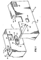
- FIG. 1 depicts a disposable single-use 35mm camera 1 and an accessory re-usable electronic flash unit 3.
- the disposable camera 1 is a point-and-shoot type and comprises (1) an inner camera part 5 including a taking lens 7, a film metering mechanism (not shown), and a single blade shutter 9 and (2) an outer sealed pack 11 which contains the inner camera part and has respective openings 13, 15, 17, 19, and 21 for the taking lens, a shutter release button 23, a frame counter window 25, a film advance thumbwheel 27, and a direct see-through viewfinder 29.
- the release button 23, the counter window 25, the thumbwheel 27, and the viewfinder 29, like the taking lens 7, are located on the inner camera part 5.
- the outer sealed pack 11 is decorative in nature and is constructed of a paper-like material, such as cardboard.
- the inner camera part 5 is constructed of plastic.
- the inner camera part 5 is loaded with a conventional 24-exposure 35mm film cartridge and substantially the entire length of the unexposed filmstrip is factory prewound from the cartridge onto a take-up spool (not shown) of the camera part.
- the thumbwheel 27 is manually rotated to rewind the exposed frame into the cartridge.
- the rewinding movement of the filmstrip the equivalent of one frame rotates a metering sprocket (not shown) to decrement a frame counter (not shown) to its next lower numbered setting.
- the single-use camera 1 is sent to a photofinisher who first removes the inner camera part 5 from the cardboard sealed pack 11 and then removes the filmstrip from the camera part. The filmstrip is processed, and the camera part and the opened pack are thrown away.
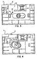
- the inner camera part 5 has a pair of flash synchronization access ports or openings 31 and 33 which extend through a front face 35 of the camera part at a location proximate the taking lens 7.
- the respective access ports 31 and 33 are aligned with corresponding recesses 37 and 39 which, as can be seen in FIG. 4, are located proximate the single blade shutter 9.
- the two access ports 31 and 33 are covered by the outer sealed pack 11. See FIG. 1.
- the re-usable flash unit 3 in addition to having a conventional flash emission device 41, includes an integral shell-like portion 43 which is dimensioned to fit over the single-use camera 1 in the manner shown in FIG. 1.
- a front wall 45 of the shell-like portion 43 has an opening 47 for the taking lens 7.
- Respective supports 49 and 51 for a pair of electrically conductive flash synchronization pins 53 and 55 are located on the inside of the front wall 45.
- the two conductive pins 53 and 55 have pointed tips to enable them to readily perforate the outer sealed pack 11.
- a flash window 57 of the flash emission device 41 is positioned in proper relation with the taking lens 7 for a flash exposure and the two conductive pins 53 and 55 are driven or forced through the outer sealed pack 11, directly into the respective access ports 31 and 33.
- the two conductive pins 53 and 55 then bottom out in the respective recesses 37 and 39. See FIG. 4.
- the shutter blade 9 is electrically conductive and is mounted for pivotable movement about a fixed pin 59, against the surging of an electrically conductive return spring 61, from a closed position shown in FIG. 4 to a fully opened position shown in FIG. 5.
- the access port 33 and its corresponding recess 39 are arranged to position the conductive pin 55 in continuous contact with one leg 63 of the return spring 61.
- Another leg 65 of the return spring 61 is connected to the shutter blade 9.
- the access port 31 and its corresponding recess 37 are arranged to position the conductive pin 53 in contact with the shutter blade 9 only when the shutter blade is fully opened.
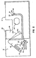
- a pivotally mounted locking/switching member 67 which, when swung from its illustrated position to an intermediate broken line position 67a, partially covers the rear of the single-use camera 1 to secure the shell-like portion 43 to the single-use camera, and which, when swung from the intermediate broken line position to a final broken line position 67b, closes a conventional normally opened flash energizing switch 69 to ready the flash emission device 41 for firing when the shutter blade 9 is fully opened.
- the locking/switching member 67 includes a cam element 71 for closing the flash energizing switch 69 and has three v-shaped cut-outs 73, 75, and 77 respectively engageable with a spring urged arresting element 81 to releasably secure the locking/switching member 67 in its three positions.
- the flash window 57 is positioned in proper relation with the taking lens 7 for a flash exposure and the two conductive pins 53 and 55 are driven through the outer sealed pack 11, directly into the respective access ports 31 and 33.
- the two conductive pins 53 and 55 then bottom out in the respective recesses 37 and 39. See FIG. 4.
- the locking/switching member 67 is swung from its illustrated position in FIG. 2 to the intermediate broken line position 67a in that FIG.
- the locking/switching member 67 is swung from its intermediate broken line position 67a in FIG. 2 to the final broken line position 67b in that FIG. to close the flash energizing switch 69.
- the flash emission device 41 is automatically fired. Since the flash output reaches its peak almost immediately, i.e. there is no firing delay, the maximum brilliance of the flash light coincides with full opening of the shutter blade 9.
- the locking/switching member 67 is left in its intermediate broken line position 67a. Then, when the shutter blade 9 is fully opened, the flash emission device 41 is not fired.
Landscapes
- Physics & Mathematics (AREA)
- General Physics & Mathematics (AREA)
- Stroboscope Apparatuses (AREA)
- Structure And Mechanism Of Cameras (AREA)
- Blocking Light For Cameras (AREA)
Abstract
Description
- The invention relates generally to the field of photography, and more particularly to a disposable single-use camera and an accessory re-usable electronic flash unit intended for use with the disposable camera.
- Recently, a disposable single-use 35mm camera referred to as the "Quick Snap" was introduced by Fuji Photo Film Co.. Ltd., and another disposable single-use 35mm camera referred to as the "
Fling 35" was introduced by Eastman Kodak Co.. Generally, each disposable camera is a point-and-shoot type and comprises (1) a plastic inner camera part including a taking lens, a film metering mechanism, and a shutter and (2) a cardboard outer sealed pack which contains the inner camera part and has respective openings for the taking lens and for a shutter release button, a frame counter window, a film advance thumbwheel, and a simple see-through viewfinder of the camera part. At the manufacturer, the inner camera part is loaded with a conventional 24-exposure 35mm film cartridge, and substantially the entire length of the unexposed filmstrip is factory prewound from the cartridge into a supply chamber of the camera part. After the customer takes a picture, the thumbwheel is manually rotated to rewind the exposed frame into the cartridge. The rewinding movement of the filmstrip the equivalent of one frame rotates a metering sprocket to decrement a frame counter to its next lower numbered setting. When substantially the entire length of the filmstrip is exposed and rewound into the cartridge, the single-use camera is sent to a photofinisher who first removes the inner camera part from the cardboard sealed pack and then removes the filmstrip from the camera part. The filmstrip is processed, and the camera part and the opened pack are thrown away. - While neither of these disposable cameras is adapted for use with an electronic flash unit, Fuji Photo Film Co. Ltd. has now made available a disposable camera having a built-in electronic flash unit. Both the camera part and the built-in flash unit are contained within the sealed pack. When the disposable camera is sent to the photofinisher, the same must be done to the built-in flash unit. The disadvantage is that this arrangement significantly increases the selling price of the camera assembly.
- FIG. 1 is a front perspective view of a disposable single-use camera and an accessory re-usable electronic flash unit, according to a preferred embodiment of the invention;
- FIG. 2 is a rear elevation view of the flash unit;
- FIG. 3 is a front elevation view of a inner camera part of the single-use camera, showing a front face of the camera part and a taking lens;
- FIG. 4 is a front elevation view of the inner camera part, showing a portion of its front face and the taking lens removed to illustrate a closed shutter; and
- FIG. 5 is a front elevation view similar to FIG. 4, illustrating the shutter fully opened.
- The above described problem associated with known disposable single-use cameras is believed solved by the invention. The invention provides a disposable single-use camera and an accessory re-usable electronic flash unit. Owing to the novel design of these two components, only the disposable camera need be returned to the photofinisher; the flash unit is retained by the customer for re-use with another disposable camera.
- According to the invention, there is provided an improved combination of a disposable single-use camera and an electronic flash unit, wherein (a) an inner camera part is pre-loaded with film and includes a taking lens and a shutter and (b) an outer sealed pack contains said camera part and has an opening for said taking lens, and wherein the improvement comprises:
said inner camera part has flash synchronization access ports;
said outer sealed pack is constructed of a perforable material which overlays said access ports; and
said flash unit includes electrically conductive flash synchronization pins shaped to perforate said outer sealed pack to enter said access ports, whereby the flash unit is removably connected to said inner camera part. - The invention is disclosed in connection with a 35mm camera and an electronic flash unit. Because such a camera and flash unit are widely known, this description is directed in particular to photographic elements forming part of or cooperating directly with the invention. It is to be understood, however, that other elements not specifically shown or described may take various forms known to persons of ordinary still in the art.
- Referring now to the drawings, FIG. 1 depicts a disposable single-use 35mm camera 1 and an accessory re-usable
electronic flash unit 3. As shown in FIGS. 1 and 2, the disposable camera 1 is a point-and-shoot type and comprises (1) aninner camera part 5 including a takinglens 7, a film metering mechanism (not shown), and a single blade shutter 9 and (2) an outer sealed pack 11 which contains the inner camera part and hasrespective openings shutter release button 23, aframe counter window 25, afilm advance thumbwheel 27, and a direct see-throughviewfinder 29. Therelease button 23, thecounter window 25, thethumbwheel 27, and theviewfinder 29, like the takinglens 7, are located on theinner camera part 5. The outer sealed pack 11 is decorative in nature and is constructed of a paper-like material, such as cardboard. Theinner camera part 5 is constructed of plastic. - At the manufacturer, the
inner camera part 5 is loaded with a conventional 24-exposure 35mm film cartridge and substantially the entire length of the unexposed filmstrip is factory prewound from the cartridge onto a take-up spool (not shown) of the camera part. After the customer takes a picture by depressing therelease button 23, thethumbwheel 27 is manually rotated to rewind the exposed frame into the cartridge. The rewinding movement of the filmstrip the equivalent of one frame rotates a metering sprocket (not shown) to decrement a frame counter (not shown) to its next lower numbered setting. When substantially the entire length of the filmstrip is exposed and rewound into the cartridge, the single-use camera 1 is sent to a photofinisher who first removes theinner camera part 5 from the cardboard sealed pack 11 and then removes the filmstrip from the camera part. The filmstrip is processed, and the camera part and the opened pack are thrown away. - As shown in FIG. 3, the
inner camera part 5 has a pair of flash synchronization access ports oropenings front face 35 of the camera part at a location proximate the takinglens 7. Therespective access ports recesses access ports - The
re-usable flash unit 3, in addition to having a conventionalflash emission device 41, includes an integral shell-like portion 43 which is dimensioned to fit over the single-use camera 1 in the manner shown in FIG. 1. Afront wall 45 of the shell-like portion 43 has anopening 47 for the takinglens 7.Respective supports front wall 45. The twoconductive pins like portion 43 is fit over the single-use camera 1 as shown in FIG. 1, aflash window 57 of theflash emission device 41 is positioned in proper relation with the takinglens 7 for a flash exposure and the twoconductive pins respective access ports conductive pins respective recesses - The shutter blade 9 is electrically conductive and is mounted for pivotable movement about a fixed
pin 59, against the surging of an electricallyconductive return spring 61, from a closed position shown in FIG. 4 to a fully opened position shown in FIG. 5. Theaccess port 33 and itscorresponding recess 39 are arranged to position theconductive pin 55 in continuous contact with oneleg 63 of thereturn spring 61. Anotherleg 65 of thereturn spring 61 is connected to the shutter blade 9. Theaccess port 31 and itscorresponding recess 37 are arranged to position theconductive pin 53 in contact with the shutter blade 9 only when the shutter blade is fully opened. When the twoconductive pins access ports recesses flash emission device 41. - As shown in FIG. 2, at the back of the
flash emission device 41, there is provided a pivotally mounted locking/switchingmember 67 which, when swung from its illustrated position to an intermediate broken line position 67a, partially covers the rear of the single-use camera 1 to secure the shell-like portion 43 to the single-use camera, and which, when swung from the intermediate broken line position to a finalbroken line position 67b, closes a conventional normally openedflash energizing switch 69 to ready theflash emission device 41 for firing when the shutter blade 9 is fully opened. The locking/switchingmember 67 includes acam element 71 for closing theflash energizing switch 69 and has three v-shaped cut-outs element 81 to releasably secure the locking/switchingmember 67 in its three positions. - When the shell-
like portion 43 is fit over the single-use camera 1 as shown in FIG. 1, theflash window 57 is positioned in proper relation with the takinglens 7 for a flash exposure and the twoconductive pins respective access ports conductive pins respective recesses - To secure the shell-
like portion 43 to the single-use camera 1, the locking/switchingmember 67 is swung from its illustrated position in FIG. 2 to the intermediate broken line position 67a in that FIG. Should flash photography rather than daylight photography be desired, the locking/switchingmember 67 is swung from its intermediate broken line position 67a in FIG. 2 to the finalbroken line position 67b in that FIG. to close theflash energizing switch 69. Then, when the shutter blade 9 is fully opened, theflash emission device 41 is automatically fired. Since the flash output reaches its peak almost immediately, i.e. there is no firing delay, the maximum brilliance of the flash light coincides with full opening of the shutter blade 9. Should daylight photography rather than flash photography be desired, the locking/switchingmember 67 is left in its intermediate broken line position 67a. Then, when the shutter blade 9 is fully opened, theflash emission device 41 is not fired. - The invention has been described with reference to a preferred embodiment. However, it will be appreciated that variations and modifications can be effected within the ordinary skill in the art without departing from the scope of the invention. For example, instead of using the shell-
like portion 43 to position the twoconductive pins respective access ports
Claims (10)
said inner camera part (5) has flash synchronization access ports (31, 33);
said outer sealed pack (11) is constructed of a perforable material (35) which overlays said access ports (31, 33); and
said flash unit (3) includes electrically conductive flash synchronization pins (53, 55) shaped to perforate said outer sealed pack (11) to enter said access ports (31, 33), to connect the flash unit to said inner camera part (5).
electrically conductive flash synchronization pins (53, 55) are shaped to perforate said outer sealed pack (11) to enter said access ports (31, 33), to removably connect said flash unit (3) to said inner camera part (5).
integral means (43) is provided for positioning said flash unit relative to said outer sealed pack (11) to locate the flash unit in proper relation with said taking lens (7) for a flash exposure and to drive said conductive pins (53, 53) through the sealed pack into said access ports (31, 33).
said outer sealed pack (11) is constructed of a perforable material (35) which can be perforated by said conductive pins (53, 55); and
said inner camera part (5) has flash synchronization access ports (31, 33) arranged directly behind said outer sealed pack (11) to immediately receive said conductive pins (53, 55) when the pins perforate the sealed pack.
Applications Claiming Priority (2)
| Application Number | Priority Date | Filing Date | Title |
|---|---|---|---|
| US07/157,239 US4801957A (en) | 1988-02-18 | 1988-02-18 | Disposable single-use camera and accessory re-usable electronic flash unit |
| US157239 | 1988-02-18 |
Publications (3)
| Publication Number | Publication Date |
|---|---|
| EP0332832A2 true EP0332832A2 (en) | 1989-09-20 |
| EP0332832A3 EP0332832A3 (en) | 1989-10-18 |
| EP0332832B1 EP0332832B1 (en) | 1993-05-05 |
Family
ID=22562904
Family Applications (1)
| Application Number | Title | Priority Date | Filing Date |
|---|---|---|---|
| EP89101895A Expired - Lifetime EP0332832B1 (en) | 1988-02-18 | 1989-02-03 | Disposable single-use camera and accessory re-usable electronic flash unit |
Country Status (5)
| Country | Link |
|---|---|
| US (1) | US4801957A (en) |
| EP (1) | EP0332832B1 (en) |
| JP (1) | JP2783828B2 (en) |
| DE (1) | DE68906296T2 (en) |
| ES (1) | ES2040906T3 (en) |
Cited By (2)
| Publication number | Priority date | Publication date | Assignee | Title |
|---|---|---|---|---|
| EP0465897A3 (en) * | 1990-07-09 | 1993-03-10 | Fuji Photo Film Co., Ltd. | A lens-fitted main body of a camera |
| EP0537908A3 (en) * | 1991-10-18 | 1993-05-19 | Konica Corporation | Photographing unit |
Families Citing this family (79)
| Publication number | Priority date | Publication date | Assignee | Title |
|---|---|---|---|---|
| GB2206221B (en) * | 1987-06-05 | 1991-11-27 | Fuji Photo Film Co Ltd | Electronic flash for a camera |
| DE3905310C2 (en) * | 1988-02-22 | 2003-02-27 | Fuji Photo Film Co Ltd | disposable camera |
| USD321705S (en) | 1988-08-31 | 1991-11-19 | Fuji Photo Film Co., Ltd. | Disposable camera |
| US4901097A (en) * | 1989-04-07 | 1990-02-13 | Eastman Kodak Company | Disposable single-use camera with lens shade |
| US4882600A (en) * | 1989-04-07 | 1989-11-21 | Eastman Kodak Company | Underwater disposable single-use camera |
| US5045871A (en) * | 1989-06-30 | 1991-09-03 | Reinholdson Mark R | Disposable camera |
| US4973998A (en) * | 1990-01-16 | 1990-11-27 | Eastman Kodak Company | Disposable single-use camera and accessory re-usable electronic flash unit |
| US5021811A (en) * | 1990-06-21 | 1991-06-04 | Eastman Kodak Company | Recycleable element recycle counter and method |
| USD332109S (en) | 1990-08-01 | 1992-12-29 | Fuji Photo Film Co., Ltd. | Disposable camera |
| USD330563S (en) | 1990-08-02 | 1992-10-27 | Fuji Photo Film Co., Ltd. | Disposable camera |
| USD330564S (en) | 1990-08-02 | 1992-10-27 | Fuji Photo Film Co., Ltd. | Disposable camera |
| USD328911S (en) | 1990-08-07 | 1992-08-25 | Fuji Photo Film Co., Ltd. | Disposable camera |
| US5146256A (en) * | 1991-02-19 | 1992-09-08 | Eastman Kodak Company | Close-up attachment for single-use camera |
| US5189453A (en) * | 1991-04-19 | 1993-02-23 | Eastman Kodak Company | Method and system for pre-exposing information on a filmstrip |
| JP2914587B2 (en) * | 1991-04-19 | 1999-07-05 | 富士写真フイルム株式会社 | Film unit with lens and method of manufacturing the same |
| USD328912S (en) | 1991-08-13 | 1992-08-25 | Fuji Photo Film Co., Ltd. | Disposable camera |
| US5187512A (en) * | 1991-10-21 | 1993-02-16 | Polaroid Corporation | Film cassette containing pre-exposed film |
| US5335033A (en) * | 1992-07-23 | 1994-08-02 | Eastman Kodak Company | Lensless camera viewfinder |
| USD338220S (en) | 1992-10-15 | 1993-08-10 | Fuji Photo Film Co., Ltd. | Camera |
| JP2865504B2 (en) * | 1992-11-16 | 1999-03-08 | 富士写真フイルム株式会社 | How to separate the package |
| USD352303S (en) | 1993-05-14 | 1994-11-08 | Eastman Kodak Company | Single-use camera with built-in flash |
| USD353607S (en) | 1993-07-01 | 1994-12-20 | Fuji Photo Film Co., Ltd. | Single use camera |
| US5384613A (en) * | 1994-01-14 | 1995-01-24 | Eastman Kodak Company | Single-use camera with weakened area to access film cassette |
| USD363078S (en) | 1994-03-31 | 1995-10-10 | Fuji Photo Film Co., Ltd. | Single use camera |
| USD359745S (en) | 1994-04-06 | 1995-06-27 | Fuji Photo Film Co., Ltd. | Single-use camera |
| US5765062A (en) * | 1994-04-19 | 1998-06-09 | Keepsake, Inc. | Reusable fun photography double exposure camera |
| US5546146A (en) * | 1994-04-19 | 1996-08-13 | Keepsake, Inc. | Single use camera film pre-exposure method |
| US5875362A (en) * | 1995-12-28 | 1999-02-23 | Eastman Kodak Company | Single-use flash camera with emergency strobe or continuous illumination enhancements |
| US5835795A (en) * | 1996-06-25 | 1998-11-10 | Photo Dimensions | Blended photographic composite images |
| US5748987A (en) * | 1996-06-25 | 1998-05-05 | Photo Dimensions | Producing smoothly blended double exposure composite images |
| US5615396A (en) * | 1996-06-25 | 1997-03-25 | Photo Dimensions | Producing smoothly blended double exposure composite images |
| USD410481S (en) * | 1997-05-13 | 1999-06-01 | Ronald G. Roncal | Photography booth |
| US6304730B1 (en) | 1999-04-29 | 2001-10-16 | Eastman Kodak Company | Film cassette having an indication of underexposure |
| US6485461B1 (en) | 2000-04-04 | 2002-11-26 | Insulet, Inc. | Disposable infusion device |
| EP1335764B1 (en) * | 2000-09-08 | 2007-06-06 | Insulet Corporation | Device and system for patient infusion |
| US6669669B2 (en) | 2001-10-12 | 2003-12-30 | Insulet Corporation | Laminated patient infusion device |
| DE60132507T2 (en) | 2000-11-09 | 2008-12-24 | Insulet Corp., Beverly | Device for the transcutaneous delivery of drugs |
| JP2004532664A (en) | 2000-12-21 | 2004-10-28 | インシュレット コーポレイション | Medical device remote control device and method |
| WO2002068015A2 (en) | 2001-02-22 | 2002-09-06 | Insulet Corporation | Modular infusion device and method |
| US20040078028A1 (en) * | 2001-11-09 | 2004-04-22 | Flaherty J. Christopher | Plunger assembly for patient infusion device |
| US6692457B2 (en) * | 2002-03-01 | 2004-02-17 | Insulet Corporation | Flow condition sensor assembly for patient infusion device |
| US6830558B2 (en) | 2002-03-01 | 2004-12-14 | Insulet Corporation | Flow condition sensor assembly for patient infusion device |
| US6839510B2 (en) * | 2002-03-28 | 2005-01-04 | Fuji Photo Film Co., Ltd. | Lens-fitted photo film unit, flash device, and lens-fitted photo film system |
| US6656159B2 (en) | 2002-04-23 | 2003-12-02 | Insulet Corporation | Dispenser for patient infusion device |
| US6960192B1 (en) | 2002-04-23 | 2005-11-01 | Insulet Corporation | Transcutaneous fluid delivery system |
| US20050238507A1 (en) * | 2002-04-23 | 2005-10-27 | Insulet Corporation | Fluid delivery device |
| US20040153032A1 (en) * | 2002-04-23 | 2004-08-05 | Garribotto John T. | Dispenser for patient infusion device |
| US6656158B2 (en) | 2002-04-23 | 2003-12-02 | Insulet Corporation | Dispenser for patient infusion device |
| JP3854190B2 (en) * | 2002-04-26 | 2006-12-06 | 株式会社ジェイテクト | Motor control device |
| US6723072B2 (en) | 2002-06-06 | 2004-04-20 | Insulet Corporation | Plunger assembly for patient infusion device |
| US7018360B2 (en) * | 2002-07-16 | 2006-03-28 | Insulet Corporation | Flow restriction system and method for patient infusion device |
| US7144384B2 (en) * | 2002-09-30 | 2006-12-05 | Insulet Corporation | Dispenser components and methods for patient infusion device |
| US7128727B2 (en) * | 2002-09-30 | 2006-10-31 | Flaherty J Christopher | Components and methods for patient infusion device |
| US20040116866A1 (en) * | 2002-12-17 | 2004-06-17 | William Gorman | Skin attachment apparatus and method for patient infusion device |
| US20050182366A1 (en) * | 2003-04-18 | 2005-08-18 | Insulet Corporation | Method For Visual Output Verification |
| US20050065760A1 (en) * | 2003-09-23 | 2005-03-24 | Robert Murtfeldt | Method for advising patients concerning doses of insulin |
| US20050070847A1 (en) * | 2003-09-29 | 2005-03-31 | Van Erp Wilhelmus Petrus Martinus Maria | Rapid-exchange balloon catheter with hypotube shaft |
| US20060178633A1 (en) * | 2005-02-03 | 2006-08-10 | Insulet Corporation | Chassis for fluid delivery device |
| US7552240B2 (en) * | 2005-05-23 | 2009-06-23 | International Business Machines Corporation | Method for user space operations for direct I/O between an application instance and an I/O adapter |
| WO2013149186A1 (en) | 2012-03-30 | 2013-10-03 | Insulet Corporation | Fluid delivery device with transcutaneous access tool, insertion mechansim and blood glucose monitoring for use therewith |
| USD709875S1 (en) * | 2013-03-15 | 2014-07-29 | Samsung Electronics Co., Ltd. | Electronic device |
| US10441717B2 (en) | 2014-04-15 | 2019-10-15 | Insulet Corporation | Monitoring a physiological parameter associated with tissue of a host to confirm delivery of medication |
| WO2017091624A1 (en) | 2015-11-24 | 2017-06-01 | Insulet Corporation | Wearable automated medication delivery system |
| WO2017091584A1 (en) | 2015-11-25 | 2017-06-01 | Insulet Corporation | Wearable medication delivery device |
| EP3538179B1 (en) | 2016-11-11 | 2023-07-26 | Insulet Corporation | Drug delivery systems with sealed and sterile fluid paths and methods of providing the same |
| WO2018156548A1 (en) | 2017-02-22 | 2018-08-30 | Insulet Corporation | Needle insertion mechanisms for drug containers |
| US10722640B2 (en) | 2017-08-03 | 2020-07-28 | Insulet Corporation | Devices, systems, and methods of packaging for a pre-filled drug delivery device |
| US10973939B2 (en) | 2017-08-03 | 2021-04-13 | Insulet Corporation | System and method for aseptic packaging of a drug delivery device components |
| EP4306146A3 (en) | 2017-09-25 | 2024-01-24 | Insulet Corporation | Pre-filled cartridge-based drug delivery device |
| EP3687600B1 (en) | 2017-09-26 | 2022-04-27 | Insulet Corporation | Needle mechanism module for drug delivery device |
| US11147931B2 (en) | 2017-11-17 | 2021-10-19 | Insulet Corporation | Drug delivery device with air and backflow elimination |
| US11241532B2 (en) | 2018-08-29 | 2022-02-08 | Insulet Corporation | Drug delivery system with sensor having optimized communication and infusion site |
| US12458751B2 (en) | 2020-10-02 | 2025-11-04 | Insulet Corporation | Fluid delivery device having multiple penetrating elements |
| US12433512B2 (en) | 2020-12-18 | 2025-10-07 | Insulet Corporation | Adhesive pad with a metallic coil for securing an on-body medical device |
| US12496398B2 (en) | 2021-05-28 | 2025-12-16 | Insulet Corporation | Threshold based automatic glucose control response |
| WO2022251642A1 (en) | 2021-05-28 | 2022-12-01 | Insulet Corporation | Spring-based status sensors |
| US12406760B2 (en) | 2021-06-07 | 2025-09-02 | Insulet Corporation | Exercise safety prediction based on physiological conditions |
| US12478738B2 (en) | 2021-11-04 | 2025-11-25 | Insulet Corporation | Methods and systems for sterilizing sealed components of a drug delivery device |
| EP4565295A1 (en) | 2022-08-04 | 2025-06-11 | Insulet Corporation | Pump mechanism with double reservoir and stationary fluid ports |
Family Cites Families (8)
| Publication number | Priority date | Publication date | Assignee | Title |
|---|---|---|---|---|
| DE1685596B2 (en) * | 1966-12-24 | 1978-06-29 | Schubert & Salzer Maschinenfabrik Ag, 8070 Ingolstadt | Working method and device for putting together fiber blends |
| DE2708895A1 (en) * | 1976-03-08 | 1977-09-15 | Itt Ind Gmbh Deutsche | ELECTRON FLASH ADDITIONAL |
| US4226517A (en) * | 1979-04-30 | 1980-10-07 | A 1000 Words Incorporated | Camera device |
| DE8330053U1 (en) * | 1983-03-21 | 1984-09-27 | W. Haking Enterprises, Ltd., Hongkong | STILL IMAGE CAMERA WITH A HOUSING |
| US4666274A (en) * | 1984-10-05 | 1987-05-19 | Canon Kabushiki Kaisha | Waterproof camera |
| DE8717169U1 (en) * | 1986-05-19 | 1988-04-28 | Fuji Photo Film Co., Ltd., Minami-Ashigara, Kanagawa | Photographic film pack |
| US4766451A (en) * | 1986-06-30 | 1988-08-23 | Fuji Photo Film Co., Ltd. | Photographic film package |
| JPH0538353Y2 (en) * | 1986-08-19 | 1993-09-28 |
-
1988
- 1988-02-18 US US07/157,239 patent/US4801957A/en not_active Expired - Fee Related
-
1989
- 1989-02-03 DE DE89101895T patent/DE68906296T2/en not_active Expired - Fee Related
- 1989-02-03 ES ES198989101895T patent/ES2040906T3/en not_active Expired - Lifetime
- 1989-02-03 EP EP89101895A patent/EP0332832B1/en not_active Expired - Lifetime
- 1989-02-13 JP JP1033501A patent/JP2783828B2/en not_active Expired - Lifetime
Cited By (2)
| Publication number | Priority date | Publication date | Assignee | Title |
|---|---|---|---|---|
| EP0465897A3 (en) * | 1990-07-09 | 1993-03-10 | Fuji Photo Film Co., Ltd. | A lens-fitted main body of a camera |
| EP0537908A3 (en) * | 1991-10-18 | 1993-05-19 | Konica Corporation | Photographing unit |
Also Published As
| Publication number | Publication date |
|---|---|
| ES2040906T3 (en) | 1993-11-01 |
| JPH01303420A (en) | 1989-12-07 |
| EP0332832A3 (en) | 1989-10-18 |
| US4801957A (en) | 1989-01-31 |
| EP0332832B1 (en) | 1993-05-05 |
| DE68906296D1 (en) | 1993-06-09 |
| DE68906296T2 (en) | 1993-12-02 |
| JP2783828B2 (en) | 1998-08-06 |
Similar Documents
| Publication | Publication Date | Title |
|---|---|---|
| EP0332832B1 (en) | Disposable single-use camera and accessory re-usable electronic flash unit | |
| US4973998A (en) | Disposable single-use camera and accessory re-usable electronic flash unit | |
| US5729768A (en) | One-time use camera provided with frangible flash support destroyed by opening lighttight enclosure to remove exposed film | |
| US4903058A (en) | Re-usable electronic flash unit for disposable single-use camera | |
| US5797044A (en) | One-time-use camera with throw-away foldable carrier for flat battery | |
| KR19990003274A (en) | Recyclable Disposable Camera | |
| US5146256A (en) | Close-up attachment for single-use camera | |
| EP0721141B1 (en) | Photographic camera with film-loading/unloading device | |
| US5913083A (en) | Camara-to-flash unit attachment assembly | |
| US5285228A (en) | Photographic film package with anti-reflection substance for viewfinder | |
| US5384613A (en) | Single-use camera with weakened area to access film cassette | |
| US4901097A (en) | Disposable single-use camera with lens shade | |
| US5530507A (en) | Method of assembling one-time-use camera | |
| US5313240A (en) | Single-use camera with removable end portion for cartridge access | |
| US5412446A (en) | Film assembly apparatus and method for single-use camera employing film securement web | |
| US5471270A (en) | Spool drive for film cartridge in single-use camera | |
| US5752087A (en) | One-time-use camera with front and rear cover parts that can be bent apart to permit battery to drop out of chamber | |
| US6035128A (en) | One-time-use camera with hinge-connected front and rear cover parts | |
| US6064823A (en) | Camera housing with integral carry strap retainer | |
| JP2000066285A (en) | Film unit with lens | |
| JPH068587Y2 (en) | Film unit with lens | |
| US5555062A (en) | Recyclable single-use camera with replaceable front lens element | |
| US5930534A (en) | Flip-up flash which integrates with film roll chamber when folded to make one-time-use camera compact | |
| US5864718A (en) | One-time use camera with multi-lamp flash | |
| US6078749A (en) | One-time-use camera with outer cover connected to inner film door to open inner film door when outer cover disengaged from camera |
Legal Events
| Date | Code | Title | Description |
|---|---|---|---|
| PUAI | Public reference made under article 153(3) epc to a published international application that has entered the european phase |
Free format text: ORIGINAL CODE: 0009012 |
|
| PUAL | Search report despatched |
Free format text: ORIGINAL CODE: 0009013 |
|
| AK | Designated contracting states |
Kind code of ref document: A2 Designated state(s): DE ES FR GB IT NL |
|
| AK | Designated contracting states |
Kind code of ref document: A3 Designated state(s): DE ES FR GB IT NL |
|
| 17P | Request for examination filed |
Effective date: 19900330 |
|
| 17Q | First examination report despatched |
Effective date: 19920529 |
|
| GRAA | (expected) grant |
Free format text: ORIGINAL CODE: 0009210 |
|
| AK | Designated contracting states |
Kind code of ref document: B1 Designated state(s): DE ES FR GB IT NL |
|
| REF | Corresponds to: |
Ref document number: 68906296 Country of ref document: DE Date of ref document: 19930609 |
|
| ITF | It: translation for a ep patent filed | ||
| ET | Fr: translation filed | ||
| REG | Reference to a national code |
Ref country code: ES Ref legal event code: FG2A Ref document number: 2040906 Country of ref document: ES Kind code of ref document: T3 |
|
| PLBE | No opposition filed within time limit |
Free format text: ORIGINAL CODE: 0009261 |
|
| STAA | Information on the status of an ep patent application or granted ep patent |
Free format text: STATUS: NO OPPOSITION FILED WITHIN TIME LIMIT |
|
| 26N | No opposition filed | ||
| PGFP | Annual fee paid to national office [announced via postgrant information from national office to epo] |
Ref country code: GB Payment date: 19950119 Year of fee payment: 7 |
|
| PGFP | Annual fee paid to national office [announced via postgrant information from national office to epo] |
Ref country code: FR Payment date: 19950207 Year of fee payment: 7 Ref country code: ES Payment date: 19950207 Year of fee payment: 7 |
|
| PGFP | Annual fee paid to national office [announced via postgrant information from national office to epo] |
Ref country code: NL Payment date: 19950228 Year of fee payment: 7 |
|
| PGFP | Annual fee paid to national office [announced via postgrant information from national office to epo] |
Ref country code: DE Payment date: 19950303 Year of fee payment: 7 |
|
| PG25 | Lapsed in a contracting state [announced via postgrant information from national office to epo] |
Ref country code: GB Effective date: 19960203 |
|
| PG25 | Lapsed in a contracting state [announced via postgrant information from national office to epo] |
Ref country code: ES Free format text: LAPSE BECAUSE OF NON-PAYMENT OF DUE FEES Effective date: 19960205 |
|
| PG25 | Lapsed in a contracting state [announced via postgrant information from national office to epo] |
Ref country code: NL Effective date: 19960901 |
|
| GBPC | Gb: european patent ceased through non-payment of renewal fee |
Effective date: 19960203 |
|
| PG25 | Lapsed in a contracting state [announced via postgrant information from national office to epo] |
Ref country code: FR Effective date: 19961031 |
|
| NLV4 | Nl: lapsed or anulled due to non-payment of the annual fee |
Effective date: 19960901 |
|
| PG25 | Lapsed in a contracting state [announced via postgrant information from national office to epo] |
Ref country code: DE Effective date: 19961101 |
|
| REG | Reference to a national code |
Ref country code: FR Ref legal event code: ST |
|
| REG | Reference to a national code |
Ref country code: ES Ref legal event code: FD2A Effective date: 19990301 |
|
| PG25 | Lapsed in a contracting state [announced via postgrant information from national office to epo] |
Ref country code: IT Free format text: LAPSE BECAUSE OF NON-PAYMENT OF DUE FEES Effective date: 20050203 |